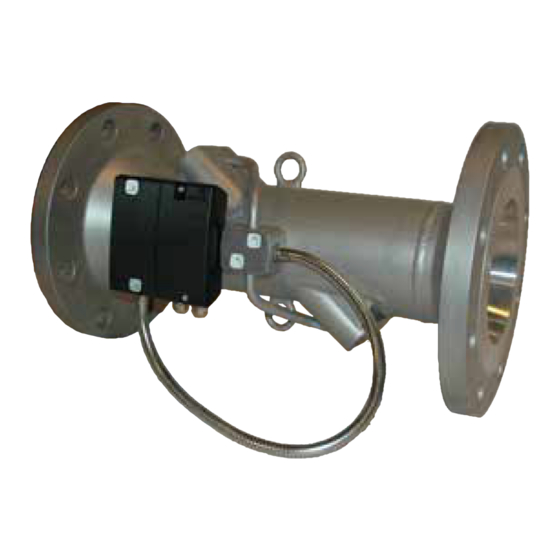
Kamstrup ULTRAFLOW 54 Installation Manual
Dn150-300
Hide thumbs
Also See for ULTRAFLOW 54:
- Technical description (77 pages) ,
- Technical description (62 pages) ,
- Installation and user manual (24 pages)
Table of Contents
Advertisement
Advertisement
Table of Contents

Summary of Contents for Kamstrup ULTRAFLOW 54
- Page 1 Installation Guide ULTRAFLOW® 54 · DN150-300...
-
Page 2: Table Of Contents
ULTRAFLOW® 54 to MULTICAL® 1.3 Straight inlet Calculator with two low sensors 1.4 Operating pressure Operational check Electrical connection Accessories 2.1 Connection to calculator 2.1.1 ULTRAFLOW® 54 and MULTICAL®, galvanically coupled 2.1.2 ULTRAFLOW® 54 and MULTICAL®, galvanically separated Kamstrup A/S • 5512887_B2_GB_09.2015... -
Page 3: Installation
For battery supply a lithium battery with connector from Kamstrup A/S must be used. Lithium batteries must be correctly handled and disposed of (see Kamstrup document 5510-408, ”Lithium batteries - Handling and disposal”). -
Page 4: Installation Angle Of Ultraflow® 54
The enclosed distance piece can be used to secure optimal position of the electronics box (see paragraph 1.2 ”Mounting of ULTRAFLOW® 54 electronics box”, page 5) Figure 2 Figure 3 Kamstrup A/S • 5512887_B2_GB_09.2015... -
Page 5: Electronics Box
(see paragraph 1.2.1 ”Orientation of low sensor electronics box”, page 7). Alternatively, the electronics box can be wall mounted as long as the distance to low sensor Figure 5 housing and pipe installation is minimum 170 mm. Kamstrup A/S • 5512887_B2_GB_09.2015... - Page 6 See Figure 7. Alternatively, the electronics box can be wall mounted at a suitable distance to the installation (minimum 170 mm). Figure 7 Kamstrup A/S • 5512887_B2_GB_09.2015...
-
Page 7: Orientation Of Low Sensor Electronics Box
- 5 °C). Furthermore, the steel tube and wires must in general hang freely downwards after the cable connections to form a drip nose for drainage of water and condensation. Max 90° Max 90° Figure 8 Kamstrup A/S • 5512887_B2_GB_09.2015... -
Page 8: Straight Inlet
In order to prevent cavitation the back pressure (the pressure at the low sensor outlet) at ULTRAFLOW® 54 must be min. 1.5 bar at q and min. 2.5 bar at q . This applies to temperatures up to approx. 80 °C. Kamstrup A/S • 5512887_B2_GB_09.2015... -
Page 9: Electrical Connection
If ULTRAFLOW® 54 and MULTICAL® are connected via output module (Y=2 or 3) ULTRAFLOW® 54 is galvanically separated from MULTICAL®. Note: Flow info cannot be read. Diagram 1 – Three-wire connection, MULTICAL® 602/801 via output module (Y=2). Cable length up to 25 metres. Kamstrup A/S • 5512887_B2_GB_09.2015... - Page 10 24 VDC supply. Cable length up to 100 metres. If long signal cables are used, installation requires careful consideration. Due to EMC there must be a distance of min. 25 cm between signal cables and all other cables. Kamstrup A/S • 5512887_B2_GB_09.2015...
-
Page 11: Connection Of Power Supply
The battery supply may only be replaced by a corresponding lithium battery with connector from Kamstrup A/S. Used batteries must be handed in for approved destruction, f.inst. at Kamstrup A/S. (See Kamstrup document 5510-408, ”Lithium batteries - Handling and disposal”). -
Page 12: Mains Supply Cable
Note: If ULTRAFLOW® 54 is mounted with a galvanically coupled output module, or if a galvanically separated output module is used in combination with battery supply the unused cable connection must be sealed off as shown in Figure 12. Kamstrup A/S • 5512887_B2_GB_09.2015... -
Page 13: Change Of Supply Unit
(Y=1), powered by MULTICAL®. Note: Installed plug in the unused rightmost connector of the electronics box. Figure 12 ULTRAFLOW® 54 with galvanically separated output module (Y=2) and 230 VAC supply of its own. Figure 13 Kamstrup A/S • 5512887_B2_GB_09.2015... -
Page 14: Calculator With Two Low Sensors
• Electric welding* can occur * Electric welding must always be carried out with the earth pole closest to the welding point. Damage to meters due to welding is not comprised by Kamstrup’s factory guarantee. 5 Operational check Carry out an operational check when the complete meter (low sensor and calculator) has been installed and connected. - Page 15 ULTRAFLOW® 54 · DN150-300 Kamstrup A/S • 5512887_B2_GB_09.2015...
- Page 16 Kamstrup A/S • 5512887_B2_GB_09.2015...


Need help?
Do you have a question about the ULTRAFLOW 54 and is the answer not in the manual?
Questions and answers