Kamstrup Ultraflow 54 Technical Description
Hide thumbs
Also See for Ultraflow 54:
- Technical description (77 pages) ,
- Installation manual (16 pages) ,
- Installation and user manual (24 pages)

Related Manuals for Kamstrup Ultraflow 54


Summary of Contents for Kamstrup Ultraflow 54
- Page 1 Technical Description ® ULTRAFLOW Kamstrup A/S Industrivej 28, Stilling DK-8660 Skanderborg TEL: +45 89 93 10 00 FAX: +45 89 93 10 01 info@kamstrup.com www.kamstrup.com...
- Page 2 ® TECHNICAL DESCRIPTION ULTRAFLOW 5512-385 GB/05.2012/Rev. G1...
-
Page 3: Table Of Contents
® TECHNICAL DESCRIPTION ULTRAFLOW Contents General Description ......................6 Data ..........................7 Electrical data ............................7 Mechanical data ........................... 7 Flow data ............................. 8 Material ............................... 8 Type overview ......................... 9 Ordering details ......................10 Accessories ............................11 Pulse Transmitter ..........................11 Pulse Divider ............................ - Page 4 ® TECHNICAL DESCRIPTION ULTRAFLOW 8.12 Power consumption ........................... 34 8.13 Interface plug/serial data ........................34 8.14 Test mode ............................35 8.15 Externally controlled start/stop ......................35 8.16 Course of calibration by means of serial data and externally controlled start/stop ......36 ®...
- Page 5 ® TECHNICAL DESCRIPTION ULTRAFLOW Approvals ......................... 57 12.1 The Measuring Instrument Directive ....................57 12.2 CE marking ............................57 12.3 Declaration of conformity ........................58 Troubleshooting ....................... 59 Disposal ........................60 Documents ....................... 61 5512-385 GB/05.2012/Rev. G1...
-
Page 6: General Description
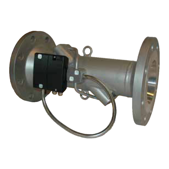
® TECHNICAL DESCRIPTION ULTRAFLOW 1 General Description ® ULTRAFLOW 54 is a static flow sensor based on the ultrasonic principle. It is primarily used as a volume flow ® ® sensor for heat meters such as MULTICAL . ULTRAFLOW has been designed for use in heating installations where water is the heat-bearing medium. -
Page 7: Data
® TECHNICAL DESCRIPTION ULTRAFLOW 2 Data ® ULTRAFLOW 2.1 Electrical data Supply voltage 3.6 V ± 0.1 V Battery 3.65 VDC, D-cell lithium (Pulse Transmitter/ Pulse Divider) Replacement interval 6 years @ t < 30°C Mains supply 230 VAC +15/-30%, 50 Hz (Pulse Transmitter/ 24 VAC ±50%, 50 Hz Pulse Divider) -
Page 8: Flow Data
® TECHNICAL DESCRIPTION ULTRAFLOW 2.3 Flow data Meter factor Flow @125 Hz Nom. flow q Nom. diameter Dynamic range ∆ ∆ ∆ ∆ p @ q Min. Cutoff [m³/h] [mm] [imp/l] [m³/h] [bar] [l/h] DN15 & DN20 1:50 & 1:100 0.04 DN15 &... -
Page 9: Type Overview
® TECHNICAL DESCRIPTION ULTRAFLOW 3 Type overview Nom. flow q Installation dimensions [m³/h] G¾Bx110 mm G1Bx130 mm (G1Bx190 mm) G¾Bx110 mm G¾Bx165 mm G1Bx130 mm G1Bx190 mm (G1Bx110 mm) (G1Bx165 mm) (DN20x190 mm) G1Bx190 mm DN20x190 mm (G1Bx130 mm) G5/4Bx260 mm DN25x260 mm G5/4Bx260 mm DN25x260 mm... -
Page 10: Ordering Details
Stainless steel 65-5- FBCM -XXX DN125 480 (488) Stainless steel XXX - code for final assembly, approvals etc. - determined by Kamstrup. A few variants may not be available in national approvals. (…) Country specific variants Table 3 5512-385 GB/05.2012/Rev. G1... -
Page 11: Accessories
® TECHNICAL DESCRIPTION ULTRAFLOW 4.1 Accessories Glands Size Nipple Union Type no. (2 pcs.) DN15 R½ G¾ 6561-323 DN20 R¾ 6561-324 DN25 G5/4 6561-325 DN32 R5/4 G1½ 6561-314 DN40 R1½ 6561-315 Table 4. Glands including gaskets (PN16). Gaskets for Gaskets for glands flange meters PN25 Size (union) Type no. - Page 12 ULTRAFLOW Pulse Divider & Pulse Divider & 11EVL (pulselength 50 ms) 11EVL (pulselength 100 ms) Meter factor Meter factor Divider Meter factor Divider [m³/h] [Pulses/l] [l/Pulse] [l/Pulse] Table 8. Table on the use together with Kamstrup EVL. 5512-385 GB/05.2012/Rev. G1...
-
Page 13: Dimensioned Sketches
® TECHNICAL DESCRIPTION ULTRAFLOW 5 Dimensioned sketches All measurements are in mm, unless otherwise stated. ® ULTRAFLOW 54, G¾B and G1B Figure 1 Thread ISO 228-1 Approx. Threads weight [ [ [ [ kg] ] ] ] G¾B 10.5 10.5 20.5 0.6;1.5) 20.5... - Page 14 ® TECHNICAL DESCRIPTION ULTRAFLOW ® ULTRAFLOW 54, G5/4B, G1½B and G2B Figure 2 Thread ISO 228-1 Approx. Threads weight [ [ [ [ kg] ] ] ] G5/4B ø43 G1½B ø61 ø61 Table 10 5512-385 GB/05.2012/Rev. G1...
- Page 15 ® TECHNICAL DESCRIPTION ULTRAFLOW ® ULTRAFLOW 54, DN20 to DN50 Figure 3 Flange EN 1092, PN25 Approx. Nom. Bolts weight diameter Number Threads [ [ [ [ kg] ] ] ] DN20 DN25 DN40 <D/2 150 DN40 <D/2 150 DN50 <D/2 165 DN50 <D/2 165...
- Page 16 ® TECHNICAL DESCRIPTION ULTRAFLOW ® ULTRAFLOW 54, DN65 to DN125 Figure 4 Flange EN 1092, PN25 Approx. Nom. Bolts weight Diameter Number Threads [ [ [ [ kg] ] ] ] DN65 <H/2 185 13.2 DN80 <H/2 200 16.8 DN80 <H/2 200 18.6 DN100...
-
Page 17: Pressure Loss
® TECHNICAL DESCRIPTION ULTRAFLOW 6 Pressure loss The pressure loss in a flow sensor is stated as the max. pressure loss at q . According to EN 1434 the max. pressure loss must not exceed 0.25 bar, unless the energy meter includes a flow controller or functions as pressure reducing equipment. -
Page 18: Installation
® ULTRAFLOW can only be connected direct to Kamstrup’s calculators on terminals 11-9-10, as shown in paragraph 7.6. Connection to other types of calculators requires the use of a Pulse Transmitter. Note: Please make sure that “pulse/litres” is identical on flow meter and calculator ®... -
Page 19: Installation Angle For Ultraflow
® TECHNICAL DESCRIPTION ULTRAFLOW ® 7.1 Installation angle for ULTRAFLOW ® ULTRAFLOW 54 may be installed horizontally, vertically, or at an angle. Important! ® For ULTRAFLOW 54 the electronics/plastic case must be placed on the side (when installed horizontally). ® ULTRAFLOW 54 may be turned up to ±45°... -
Page 20: Straight Inlet
® TECHNICAL DESCRIPTION ULTRAFLOW 7.2 Straight inlet ® ULTRAFLOW 54 requires neither straight inlet nor straight outlet to meet the Measuring Instruments Directive (MID) 2004/22/ EC, OIML R75:2002 and EN 1434:2007. A straight inlet section will only be necessary in case of heavy flow disturbances before the meter. -
Page 21: Humidity And Condensation
® Glands and short direct sensor fitted into ULTRAFLOW (only G¾B (R½) and G1B (R¾)). The short direct sensor from Kamstrup can only be mounted in PN16 installations. The blind plug mounted in the ® ULTRAFLOW flow part can be used in connection with both PN16 and PN25. - Page 22 ® TECHNICAL DESCRIPTION ULTRAFLOW ® ® Flange meter with MULTICAL /Pulse Transmitter fitted on ULTRAFLOW Figure 10 5512-385 GB/05.2012/Rev. G1...
-
Page 23: Electrical Connection
® TECHNICAL DESCRIPTION ULTRAFLOW 7.6 Electrical connection ® ® ULTRAFLOW MULTICAL → → → → Blue (ground)/11A → → → → Red (supply)/9A → → → → Yellow (signal)/10A → → → → ® ® Table 14. Connecting ULTRAFLOW and MULTICAL 3.65 VDC Supply Pulse Transmitter/ Pulse →... -
Page 24: Example Of Connecting Ultraflow ® And Multical
® TECHNICAL DESCRIPTION ULTRAFLOW ® ® 7.7 Example of connecting ULTRAFLOW and MULTICAL ® ULTRAFLOW Figure 11 7.8 Calculator with two flow sensors MULTICAL 602 can be used in various applications with two flow sensors, e.g. leak surveillance or open systems. ... - Page 25 ® TECHNICAL DESCRIPTION ULTRAFLOW In installations where the electric coupling cannot be carried out, or where welding in the pipe system can occur, the cable from one ULTRAFLOW must be routed through a Pulse Transmitter with galvanic separation before the cable enters MULTICAL 602.
-
Page 26: Functional Description
Flow sensor manufacturers have been working on alternative techniques to replace the mechanical principle. Research and development at Kamstrup has proved that ultrasonic measuring is the most viable solution. Combined with microprocessor technology and piezo ceramics, ultrasonic measuring is not only accurate but also reliable. - Page 27 ® TECHNICAL DESCRIPTION ULTRAFLOW In principle, flow is determined by measuring the flow velocity and multiplying it by the area of the measuring pipe: × where: is the flow is the flow velocity Is the area of the measuring pipe The area and the length, which the signal travels in the sensor, are well-known factors.
-
Page 28: Signal Paths
® TECHNICAL DESCRIPTION ULTRAFLOW To minimize the influence from variations of the velocity of sound in water it is measured. The velocity of sound in water is measured by means of the built-in ASIC. For this purpose a number of absolute time measurements between the two transducers are made. -
Page 29: Function
® TECHNICAL DESCRIPTION ULTRAFLOW 8.6 Function In the meter’s working area from min. cut-off to saturation flow there is a linear connection between the water volume flowing through and the number of pulses being emitted. An example of the connection between flow and ®... - Page 30 ® TECHNICAL DESCRIPTION ULTRAFLOW Meter factor Flow at 128 Hz [m³/h] [imp/l] [m³/h] 1.54 4.61 7.68 9.22 18.4 30.7 46.1 76.8 92.2 184.3 307.2 Table 17. Flow at max. pulse frequency (128 Hz). According to DS/EN 1434 the upper flow limit q is the highest flow at which the flow sensor may operate for short ®...
-
Page 31: Guidelines For Dimensioning Ultraflow
® TECHNICAL DESCRIPTION ULTRAFLOW ® 8.7 Guidelines for dimensioning ULTRAFLOW In connection with installations it has proved to be practical to work with larger pressures than the ones stated below: Nominal flow q Recommended Max. flow q Recommended back pressure back pressure [m³/h] [bar]... -
Page 32: Pulse Output
® TECHNICAL DESCRIPTION ULTRAFLOW Pulse output ® ULTRAFLOW Type Push-Pull Output impedance ~10 kΩ Pulse duration 2…5 ms Pause Depending on current pulse frequency See also block diagram below. ® Figure 14. Block diagram ULTRAFLOW 8.9 Pulse Transmitter/Pulse Divider Type Open collector. -
Page 33: Pulse Emission
® TECHNICAL DESCRIPTION ULTRAFLOW 8.10 Pulse emission Pulses are emitted at intervals of 1 sec. The number of pulses to be emitted is calculated every second. Pulses are emitted in bursts with a pulse duration of 2…5 ms and pauses depending on the current pulse frequency. The duration of the pauses between the individual bursts is approx. -
Page 34: Power Consumption
® TECHNICAL DESCRIPTION ULTRAFLOW Flow meter tolerances qi:qp 1:100 (qp 1.5 m³/h) EN1434 cl.3 EN1434 cl.2 ½ EN1434 cl.2 0,01 0.01 Flow [m³/h] 0,1x qp 0.1 x qp Diagram 5 8.12 Power consumption ® The power consumption of ULTRAFLOW is as follows: Max. -
Page 35: Test Mode
® TECHNICAL DESCRIPTION ULTRAFLOW Meter interface Pin 1 Vcc Pin 2 Gnd Pin 3 Pulse out Pin 4 Access control Figure 16. Interface plug. 8.14 Test mode ® To minimize the time spent on calibration, ULTRAFLOW 54 can be switched into test mode. In test mode (verification mode) the measuring routines only take one fourth of the time they take in normal mode. -
Page 36: Course Of Calibration By Means Of Serial Data And Externally Controlled Start/Stop
® TECHNICAL DESCRIPTION ULTRAFLOW The excess water quantity in connection with start is the water volume that runs through the sensor during the time before the first accumulation within the test period. In the same way the water quantity for the period from the last accumulation until end of test is added. -
Page 37: Calibrating Ultraflow
® TECHNICAL DESCRIPTION ULTRAFLOW ® 9 Calibrating ULTRAFLOW Calibration can be based on: Pulses in standard mode • Pulses in test mode • Pulses using PULSE TESTER type 66-99-279 • Serial data with the meter in test mode (e.g. used in connection with NOWA) •... - Page 38 ® TECHNICAL DESCRIPTION ULTRAFLOW ® Figure 19. Block diagram ULTRAFLOW Connection via three-wire cable Yellow Signal Supply Blue Ground Supply 3.6 VDC ± 0.1 V Output when using Pulse Transmitter Type Open collector. Can be connected as two-wire or three-wire via the built-in pull-up resistance of 33 kΩ.
-
Page 39: Start-Up
® TECHNICAL DESCRIPTION ULTRAFLOW Figure 20. Block diagram Pulse Transmitter. 9.3 Start-up 16 seconds must elapse from start-up to calibration in order to allow a true reading to be reached. 9.4 Measuring flow To obtain correct flow measurement, the duration of calibration must be min. 2 minutes. 9.5 Evacuation ®... -
Page 40: Suggested Test Points
® TECHNICAL DESCRIPTION ULTRAFLOW 9.6 Suggested test points Test point Test duration Test quantities Nom. flow Meter factor 0.1xq 0.1xq 0.1xq [m³/h] [impulses/l] [m³/h] [m³/h] [m³/h] [min] [min] [min] [kg] [kg] [kg] 0.006 0.06 0.015 0.15 0.025 0.25 20.2 0.035 0.35 17.1 0.06... -
Page 41: Sealing
® TECHNICAL DESCRIPTION ULTRAFLOW 10 Sealing ® ULTRAFLOW is sealed from the factory. If the sensor is verified, it will be supplied with laboratory marks and a year mark as shown in Figure 21. If the seal of a verified sensor is broken, the sensor must be verified before being installed in a location demanding verification. -
Page 42: Optimization In Connection With Calibration
® TECHNICAL DESCRIPTION ULTRAFLOW 10.1 Optimization in connection with calibration ® To make a rational test of ULTRAFLOW it must be possible to reproduce test results. This is also very important if the sensors tested are to be adjusted. ® Experience shows that ULTRAFLOW operates with standard deviations of 0.3…0.4% at q and 0.2…0.3% at q... -
Page 43: Pulse Tester
® TECHNICAL DESCRIPTION ULTRAFLOW 10.2 PULSE TESTER During a calibration process it is often practical to use PULSE TESTER type 66-99-279 with the following functions: Galvanically separated pulse outputs Integral supply for ULTRAFLOW LCD-display with counter Externally controlled ”Hold” function ... - Page 44 TECHNICAL DESCRIPTION ULTRAFLOW Flow sensor with active pulse output, supplied from the pulse tester This connection is used together with either Kamstrup’s ULTRAFLOW or Kamstrup’s electronic pick-up for vane wheel meters. Connection (M1) 9: Red (9A) 10: Yellow (10A)
-
Page 45: Hold Function
® TECHNICAL DESCRIPTION ULTRAFLOW 10.4 Hold function When the Hold input is activated (high level supplied to input), counting stops. When the Hold signal is removed (low level supplied to input), counting restarts. The counters can also be reset by pressing the right key on the front panel (Reset). Input Galvanically isolated Input protection... -
Page 46: Spare Parts
® TECHNICAL DESCRIPTION ULTRAFLOW 10.7 Spare parts Description Type No. Battery D-cell 66-00-200-100 Cable retainer (secures the battery) 1650-099 2-pole plug (female) 1643-185 3-pole plug (female) 1643-187 PCB (66-R) 5550-517 Table 23 10.8 Changing the battery If the PULSE TESTER is used continuously we recommend that the battery be replaced once a year. Connect the battery to the terminals marked ”batt.”, the red wire to + and the black one to -. -
Page 47: Metertool
® TECHNICAL DESCRIPTION ULTRAFLOW 11 METERTOOL 11.1 Introduction METERTOOL is a collection of programs for servicing Kamstrup heat meters. ® ® ”METERTOOL for ULTRAFLOW X4” is a Windows -based software. In combination with a PC and interface the ® software makes it possible to adjust ULTRAFLOW METERTOOL has been developed to provide laboratories a simple and effective access to programming/adjusting ®... - Page 48 ® TECHNICAL DESCRIPTION ULTRAFLOW ® Figure 28. Location of the four-pole plug in ULTRAFLOW ® Figure 29. Location of the four-pole plug incl. ULTRAFLOW ® ® adapter in ULTRAFLOW 14/24 (MULTICAL 61/62). 5512-385 GB/05.2012/Rev. G1...
-
Page 49: Installation
When the installation has been completed, the icon “KAMSTRUP METERTOOL” will appear from the Start menu and as a link on the desktop. Click on the new icon “KAMSTRUP METERTOOL” for the list of ”METERTOOL” programs selected during installation to be displayed. Double-click on “METERTOOL UFx4” in order to start the program ®... -
Page 50: Metertool For Ultraflow ® X4
® TECHNICAL DESCRIPTION ULTRAFLOW ® 11.3 METERTOOL for ULTRAFLOW ® The menu structure of METERTOOL for ULTRAFLOW X4 is as follows: 11.3.1 Files The menu ”Files” includes: Select Com-Port: Setup of COM port for interface of flow sensor/Pulse Divider. Exit: Terminates METERTOOL. -
Page 51: Help
® TECHNICAL DESCRIPTION ULTRAFLOW 11.3.4 Help About: Includes program numbers and revisions of the various components of the installed version. 11.4 Application Flow sensor adjustment. Before adjusting a sensor you must make sure that the sensor operates satisfactorily in the flow rig in question. ®... -
Page 52: Flow Meter Adjustment
® TECHNICAL DESCRIPTION ULTRAFLOW 11.4.2 Flow meter adjustment Open ”Flow Meter Adjustment”: ”Read from Meter”: Reads data from the connected flow sensor. Flow curve number - 5945357 - and meter dimensions appear from the heading. This number will also appear from the meter’s label. The field “Flow Curve”... -
Page 53: Pulse Divider
Reads the current coding of the Pulse Divider. ”Write”: Programs the Pulse Divider with the entered data. ”Label type”: Makes it possible to select position on Kamstrup label sheet. ”Print”: Prints Pulse Divider Label on the standard printer selected in the PC. ”Close”: Terminates Pulse Divider. -
Page 54: Technical Description Ultraflow
Pulse figure Divider Pulse figure Divider [m³/h] [imp/l] [l/Pulse] [l/Pulse] 0.25 2500 1000 0.25 2500 Table 25. Pulse division table for use together with Kamstrup EVL. For other variants, please see installation guide for Pulse Divider No. 5511-727. 5512-385 GB/05.2012/Rev. G1... -
Page 55: Meter Type
® TECHNICAL DESCRIPTION ULTRAFLOW 11.4.5 Meter type Open ”Meter type”: ”Read”: Reads flow sensor information. 11.4.6 Help Open ”About”: Displays: Revision numbers. 5512-385 GB/05.2012/Rev. G1... -
Page 56: Update
The METERTOOL database is updated by connecting the PC to the Internet and activating ”Force Database Update”. The program now connects to a Kamstrup server and downloads the newest database. After update the following message appears: The database has been updated, please open METERTOOL UFx4 again. -
Page 57: Approvals
54 is supplied with a CE-marking according to MID (2004/22/EC). The certificates have the following numbers: B-module: DK-0200-MI004-008 D-module: DK-0200-MIQA-001 Please contact Kamstrup A/S for further details on type approval and verification. 12.2 CE marking ® ULTRAFLOW 54 is marked according to the following directives: EMC directive... -
Page 58: Declaration Of Conformity
® TECHNICAL DESCRIPTION ULTRAFLOW 12.3 Declaration of conformity 5512-385 GB/05.2012/Rev. G1... -
Page 59: Troubleshooting
® TECHNICAL DESCRIPTION ULTRAFLOW 13 Troubleshooting Before sending in the sensor to be repaired or checked, please use the error detection table below to help you clarify the possible cause of the problem. Symptom Possible cause Proposal for correction No updating of display values No power supply Replace battery or check mains supply No display function (blank... -
Page 60: Disposal
• • • • Disposal by Kamstrup A/S Kamstrup accepts worn-out meters for environmentally correct disposal according to previous agreement. The disposal is free of charge to our customers, except for the cost of transportation to Kamstrup. • • • • The customer sends for disposal The meters must not be disassembled prior to dispatch. -
Page 61: Documents
® TECHNICAL DESCRIPTION ULTRAFLOW 15 Documents Danish English German Russian Technical Description 5512-384 5512-385 5512-575 5512-576 Data sheet 5810-588 5810-589 5810-590 5810-593 Installation instructions 5512-951 5512-952 5512-953 5512-956 Table 26 5512-385 GB/05.2012/Rev. G1... - Page 62 ® TECHNICAL DESCRIPTION ULTRAFLOW 5512-385 GB/05.2012/Rev. G1...
Need help?
Do you have a question about the Ultraflow 54 and is the answer not in the manual?
Questions and answers