Advertisement
FT2A-PWR-EU-1-C14
AC Power Outlet Module for FT2 Series, European/Schuko, C14 Inlet
Installation Guide
Description
The Crestron
FT2A-PWR-EU-1-C14 module provides one European "Schuko" type ac
®
power outlet for use with the FT2 series of FlipTop™ cable managment devices. The
module may be used to power laptops and other ac-powered devices at the table.
The FT2A-PWR-EU-1-C14 module is suitable for use in Europe, Korea, and other
countries or regions where Plug Type F power outlets are used.
Additional Resources
Visit the product page on the Crestron website (www.crestron.com)
for additional information and the latest rmware updates. Use a QR
reader application on your mobile device to scan the QR image.
Overview
The FT2A-PWR-EU-1-C14 has the following speci cations:
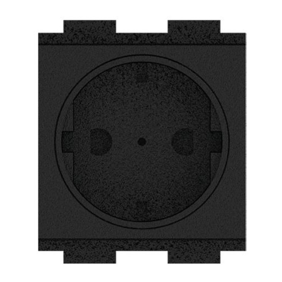
• Each FT2A-PWR-EU-1-C14 module provides one European "Schuko" Type F
ac power outlet that is rated for 10 A (total) at 220–240 Vac, 50/60 Hz.
• An IEC C-14 socket is provided on the bottom of each module, which is used to
connect the module to a power source via an IEC power cord rated for 10 A or better
(not included).
• One blank plate is provided with the FT2A-PWR-EU-1-C14 module for use with
low-pro le power cords.
NOTE: If low-pro le power cords are expected to be used with the
FT2A-PWR-EU-1-C14 module, ensure that the provided blank plate is installed to the
left of the module.
FT2A-PWR-EU-1-C14
module
Each module is 1.97 x 1.97 in (50 x 50 mm) and occupies two empty module spaces in an
FT2 series assembly.
Blank plate
Installation
Use the following procedure to install the FT2A-PWR-EU-1-C14 module into an FT2 series
assembly.
If the FT2A-PWR-EU-1-C14 module is being installed as part of a new FT2 series FlipTop
device installation, proceed to step 3 below.
Install the FT2A-PWR-EU-1-C14 Module
1. Remove the magnetic bezel from the FT2 series assembly by grasping the inside of
the bezel and pulling it up and away rmly from the assembly until the magnetic hold
is broken.
2. Unscrew and remove the two locking bars that secure the module row required for
installation.
For example, if installing the FT2A-PWR-EU-1-C14 module in the front row of an
FT2-700 series FlipTop device, remove the front and center locking bars.
Locking bar
(center)
Locking bar
(front)
3. Connect an IEC power cord (rated for 10 A or better) to the IEC C-14 socket on the
bottom of the FT2A-PWR-EU-1-C14 module.
FT2A-PWR-EU-1-C14
module (bottom view)
IEC C-14
socket
Locking bar
(rear)
Advertisement
Table of Contents

Related Manuals for Crestron FT2A-PWR 1-C14 Series


Summary of Contents for Crestron FT2A-PWR 1-C14 Series
- Page 1 Additional Resources is broken. 2. Unscrew and remove the two locking bars that secure the module row required for Visit the product page on the Crestron website (www.crestron.com) installation. for additional information and the latest rmware updates. Use a QR reader application on your mobile device to scan the QR image.
- Page 2 Crestron disclaims any proprietary interest in the marks and names of others. Crestron is not responsible for errors in typography or photography.
Need help?
Do you have a question about the FT2A-PWR 1-C14 Series and is the answer not in the manual?
Questions and answers