
Related Manuals for DeLonghi PEMA 96


Summary of Contents for DeLonghi PEMA 96
- Page 1 DE ’ L O N G H I C OO KING USERS OPERATING INSTRUCTIONS INSTALLATION INSTRUCTIONS DUA L FU E L CO OK E RS...
- Page 2 Dear Customer, Thank you for having purchased and given your preference to our product. The safety precautions and recommendations reported below are for your own safety and that of others. They will also provide a means by which to make full use of the features offered by your appliance.
-
Page 3: Important Safety Precautions And Recommendations
IMPORTANT SAFETY PRECAUTIONS AND RECOMMENDATIONS IMPORTANT: This appliance is designed and manufactured solely for the cooking of domestic (household) food and is not suitable for any non domestic application and therefore should not be used in a commercial environment. The appliance guarantee will be void if the appliance is used within a non domestic environment i.e. - Page 4 • CAUTION: this appIiance must only be installed in a permanently ventilated room in compliance with the applicable regulations. • Do not operate your appliance by means of an external timer or separate remote-control system. • Do not carry out cleaning or maintenance operations on the appliance without having previously disconnected it from the electric power supply.
- Page 5 • WARNING: During use the appliance and its accessible parts become hot; they remain hot for some time after use. Care should be taken to avoid touching heating elements (on – the hob and inside the oven). The door is hot, use the handle. –...
- Page 6 • Do not line the oven walls or base with aluminium foil. Do not place baking trays or the drip tray on the base of the oven chamber. • Do not cover the hob with aluminium foils. FIRE RISK! Do not store flammable material in the oven or in the •...
-
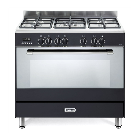
Page 7: Cooking Hob
COOKING HOB Fig. 1.1 GAS BURNERS AND ELECTRICAL PLATES Auxiliary burner (A) 1,00 kW Semi-rapid burner (SR) 1,75 kW Rapid burner (R) 3,00 kW Triple-ring (TR) 4,00 kW Notes: • The electric ignition is incorporated in the knobs. The appliance has a safety valve system fitted, the flow of gas will be stopped if and •... -
Page 8: Control Panel
CONTROL PANEL Fig. 2.1 CONTROLS DESCRIPTION Front right burner control knob Rear right burner control knob Central burner control knob Rear left burner control knob Front left burner control knob Multifunction oven thermostat control knob Multifunction oven function selector control knob Electronic clock/programmer Oven thermostat indicator light Note:... -
Page 9: Use Of The Hob Burners
USE OF THE HOB BURNERS GAS BURNERS Gas flow to the burners is adjusted by turning the knobs (illustrated in fig. 3.1) which control the safety valves. Make the symbol of the knob match with the indicator on the control panel to obtain: - symbol closed valve maximum... -
Page 10: Lighting The Burners
LIGHTING THE BURNERS CHOICE OF THE BURNER ignite burner, following On the control panel, near every knob instructions are to be followed: there is a diagram that indicates which burner is controlled by that knob. Press in the corresponding knob and turn counter-clockwise (fig. -
Page 11: Multifunction Oven
MULTIFUNCTION OVEN OPERATING PRINCIPLES Attention: The oven door becomes Heating cooking very hot during operation. MULTIFUNCTION oven are obtained in the Keep children away. following ways: by normal convection The heat is produced by the upper and GENERAL FEATURES lower heating elements. As its name indicates, this is an oven by forced convection that presents particular features from an... - Page 12 Fig. 4.1 Fig. 4.2 (fig. 4.2) THERMOSTAT KNOB To turn on the heating elements of the oven, set the function selector knob on the desired program and the thermostat knob onto the desired temperature. To set the temperature, it is necessary to make the knob indicator meet the chosen number. The elements will turn ON or OFF automatically according to the energy need which is determined by the thermostat.
- Page 13 UPPER HEATING ELEMENT In this position only the upper element is switched on. Heat is distributed by natural convection. The temperature must be regulated between 50 °C and the maximum position with the thermostat knob. Recommended for: To complete cooking of dishes that require higher temperature at the top. GRILLING The infra-red heating element is switched on.
-
Page 14: Cooking Advice
HOT AIR COOKING The circular element and the fan are on. The heat is diffused by forced convection and the temperature must be regulated between 50°C and the maximum temperature with the thermostat knob. It is not necessary to preheat the oven. Recommended for: For foods that must be well done on the outside and tender or rare on the inside, i. -
Page 15: Oven Cooking
• The introduction of the different dishes OVEN COOKING in the oven must be done at different To cook, before introducing the food, preheat times in relation to the cooking times the oven to the desired temperature. of each one. When the oven has reached the desired The time and energy saved with this type of temperature, introduce the food, control... - Page 16 ROTISSERIE This is used for spit roasting under the grill and comprises: an electric motor fitted to the rear of the oven; • • a stainless steel skewer provided with slide-out heatless handgrip and two sets of adjustable forks; a skewer support to be fitted in the middle runner. •...
-
Page 17: Electronic Programmer
ELECTRONIC PROGRAMMER The electronic programmer is a device which groups together the following functions: • 24 hours clock with illuminated display • Timer (up to 23 hours and 59 minutes) • Program for automatic oven cooking • Program for semi-automatic oven cooking Description of the buttons: Description illuminated... -
Page 18: Electronic Timer
(fig. 5.2) ELECTRONIC CLOCK ELECTRONIC TIMER The programmer is equipped with an The timer program consists only of a electronic clock with illuminated numbers buzzer which may be set for a maximum which indicates hours and minutes. period of 23 hours and 59 minutes. If the AUTO symbol is flashing push the Upon immediate connection of the oven or after a power cut, three zeros will flash on... -
Page 19: Automatic Oven Cooking
AUTOMATIC OVEN COOKING Set the temperature and the cooking program by using the switch and To cook food automatically in the oven, it is thermostat knobs of the oven (see necessary to: specific chapters). Set the length of the cooking period. oven programmed Set the end of the cooking time. -
Page 20: Semi-Automatic Cooking
SEMI-AUTOMATIC COOKING At the end of the cooking time the oven will turn off automatically, the symbol This is used to automatically switch off the will turn off, AUTO will flash and a buzzer oven after the desired cooking time has will be sound, which can be turned off by elapsed. - Page 21 IMPORTANT – OVEN NOT WORKING If the oven is not working, it may have been accidently set to “AUTOMATIC” or the power to the appliance was interrupted. If the Timer is showing the letter “AUTO” as below or the time of day is flashing, the Oven may not turn on or be delayed in its operation. Before requesting a service call, please refer to the timer set up instructions in this handbook and ensure the timer is set to “MANUAL”...
-
Page 22: Cleaning And Maintenance
CLEANING AND MAINTENANCE GLASS LID (SUPPLIED WITH SOME Models with glass lid MODELS ONLY) For cleaning purposes, the lid can be easily removed upwards once taken to the upright position. Should the hinges slip off, replace them in their housing being careful that: •... -
Page 23: General Advice
GENERAL ADVICE ENAMELLED PARTS • Before you begin cleaning, you All the enamelled parts must be cleaned must ensure that the appliance is with a sponge and soapy water or other switched off. non-abrasive products. Dry preferably with a microfibre or soft •... - Page 24 GAS TAPS BURNERS Periodic lubrication of the gas taps must be They can be removed and washed with carried out by specialist personnel only. soapy water only. In the event of operating faults in the gas They will remain always perfect if cleaned taps, call the Service Department.
- Page 25 Fig. 6.3 Fig. 6.2 Fig. 6.4 Fig. 6.6 Fig. 6.5...
- Page 26 ASSEMBLY AND DISMANTLING OF Fig. 6.7 THE SIDE RUNNER FRAMES • Fit the side runner frames “G” (interposing the catalytic panels “A”) into the holes on the side walls inside the oven (fig. 6.7). • Slide in, on the guides, the shelf and the tray etc.
-
Page 27: Replacing The Oven Lamp
REPLACING THE OVEN LAMP WARNING: Ensure the appliance is switched off and disconnected from the electrical power supply before replacing WRONG the lamp to avoid the possibility of electric shock. • Let the oven cavity and the heating elements to cool down. •... -
Page 28: Removing The Oven Door
REMOVING THE OVEN DOOR The oven door can easily be removed as follows: Open the door to the full extent (fig. • 6.11a). • Open the lever “A” completely on the left and right hinges (fig. 6.11b). Hold the door as shown in fig. 6.12d. •... - Page 29 REFIT THE DOOR Hold the door firmly (fig. 6.12a). • • Insert the hinge tongues into the slots, making sure that the groove drops into place as shown in the fig. 6.12b. • Open the door to its full extent. •...
- Page 30 REMOVING THE INNER PANE OF GLASS The oven door is fitted with no. 2 panes: • no. 1 outside; • no. 1 inner. To clean all panes on both sides it is necessary to remove the inner pane as follows: Lock the door open: Fig.
- Page 31 AFTER CLEANING, REPLACE THE INNER GLASS PANE When replacing the inner glass pane, make sure that: • You replace the pane correctly, as shown. The pane must be in the position described below in order to fit into the door and to ensure that the Fig.
- Page 32 Advice for the installer IMPORTANT • Cooker installation must only be carried out by QUALIFIED TECHNICIANS and in compliance with local safety standards. Failure to install the appliance correctly could invalidate any manufacturer’s warranty. • The appliance must be installed in compliance with regulations in force in your country and in observation of the manufacturer’s instructions.
-
Page 33: Installation
INSTALLATION The installation conditions, concerning protection against overheating of the surfaces adjacent to the cooker, must conform to figs. 7.1a or 7.1b. The appliance must be kept no less than 200 mm away from any side wall which exceeds the height of the hob surface (figs. 7.1a or 7.1b). The veneered syntetical material and the glue used must be resistant to a temperature of 90°C in order to avoid ungluing or deformations. - Page 34 FITTING THE ADJUSTABLE FEET The adjustable feet must be fitted to the base of the cooker before use (fig. 7.2). Rest the rear of the cooker on a piece of the polystyrene packaging exposing the base for the fitting of the feet. Fit the 4 legs by screwing them tight into the support base as shown in figure 7.3.
-
Page 35: Moving The Cooker
MOVING THE COOKER WARNING: When raising cooker to upright position always ensure two people carry out this manoeuvre to prevent damage to the adjustable feet (fig. 7.6). Fig. 7.6 WARNING WARNING When moving cooker to its final position Be carefull: do not lift the cooker by the DO NOT DRAG (fig. -
Page 36: Anti-Tilt Bracket
ANTI-TILT BRACKET Important! To restrain the appliance and prevent it tipping accidentally, fit a bracket to its rear to fix it securely to the wall. To fit the anti-tilt bracket: After you have located where the cooker is to be positioned, mark on the wall the place where the two screws of the anti-tilt bracket have to be fitted. -
Page 37: Ventilation Requirements
VENTILATION REQUIREMENTS The appliance must be installed in compliance with applicable local regulations concerning ventilation and the evacuation of exhaust gases. Intensive and prolonged use may require extra ventilation, e.g. opening a window, or more efficient ventilation increasing the mechanical suction power if this is fitted. CHOOSING SUITABLE SURROUNDINGS The room where the gas appliance is to be installed must have a natural flow of air so that the gas can burn (in compliance with applicable local regulations). -
Page 38: Gas Section
GAS SECTION GAS INSTALLATION REQUIREMENTS Important ! • The walls adjacent to the cooker must be of heat-resistant material. • Before installation, make sure that the local distribution conditions (gas type and pressure) and the adjustment of this appliance are compatible. The appliance adjustment conditions are given on the plate or the label. -
Page 39: Connecting The Appliance To The Gas Supply
CONNECTING THE APPLIANCE TO THE GAS SUPPLY The gas connection must be carried out by an authorised person according to the relevant standards. Ensure that the room in which the cooker is to be installed is adequately ventilated, in compliance with applicable regulations. Connect the cooker to the gas mains utilizing rigid or flexible pipes. - Page 40 POSSIBLE GAS CONNECTIONS GAS CONNECTION WITH A RUBBER HOSE Imporant! A rubber hose connection shall only be made if permitted by the applicable local regulations. The gas connection is made up of: the terminal fitting of the inlet pipe (right-hand or left-hand); •...
- Page 41 • the hose is replaced at the printed due date or if it shows signs of wear or damage, and replaced regardless of its condition after a maximum of three years. • you inform the customer that the gas cylinder valve or the gas supply valve immediately by the cooker should be closed when the cooker is not in use.
- Page 42 GAS CONNECTION WITH RIGID PIPES OR A FLEXIBLE PIPE The gas connection is made up of: the terminal fitting of the inlet pipe (right-hand or left-hand) • • sealing washer. Important! If fitted, remove the hose holder from the terminal fitting of the inlet pipe. When connecting the cooker to the gas supply with rigid pipes or a flexible pipe, make sure that you use rigid pipes or a flexible pipe complying with applicable local regulations.
- Page 43 Gas connection with rigid or flexible pipe Note: if already fitted on the inlet pipe, remove the rubber hose holder Inlet pipe Manifold male pipe fitting 1/2” G cylindrical (ISO 228-1) male Sealing washer (#) (#) If not already fitted on the inlet pipe, it is supplied with the appliance in a separate kit 1/2”...
-
Page 44: Lubrication Of The Gas Taps
GAS MAINTENANCE TABLE FOR THE CHOICE OF THE INJECTORS - Cat. 2H 3+ Natural Gas G30 28-30 mbar G20 20 mbar Nominal Reduced G31 37 mbar BURNERS power [kW] power [kW] Ø injector Ø injector [1/100 mm] [1/100 mm] Auxiliary (A) 1,00 0,30 Semi-rapid (SR) - Page 45 REPLACEMENT OF THE INJECTORS Auxiliary, Semirapid If the injectors are not supplied they can and Rapid be obtained from the “Service Centre”. burners Select the injectors to be replaced according to the “Table for the choice of the injectors”. nozzle diameters, expressed hundredths of a millimetre, are marked on...
-
Page 46: Electrical Section
ELECTRICAL SECTION • If the power supply cable is damaged it IMPORTANT: The cooker must be must be substituted by a suitable cable installed accordance with available in the after sales service. manufacturer’s instructions. N.B. For connection to the mains, do Incorrect installation, which... -
Page 47: Connection Of The Power Supply Cable
CONNECTION OF THE POWER SUPPLY CABLE WARNING: If the power supply cable is damaged, it must be replaced only by an authorised service agent in order to avoid a hazard. To connect the supply cable: Remove the screw securing the cover “A” on the rear of the cooker (fig. 9.1). •... - Page 48 Descri pt i ons an d ill ustrati ons in this booklet a re giv en as simpl y ind icat ive. T h e ma nuf a ct ur er r es erv es the right, consider ing t he cha ract eri stics o f t he models described here, at any time and without notice, to make eventual necessary mo d ifi cat i on s f or the ir constr ucti on or for com merc ial n eeds.
Need help?
Do you have a question about the PEMA 96 and is the answer not in the manual?
Questions and answers