Cognex In-Sight 2000 Series Reference Manual
Vision sensor
Hide thumbs
Also See for In-Sight 2000 Series:
- Manual (91 pages) ,
- Reference manual (54 pages) ,
- Manual (84 pages)
Table of Contents
Advertisement
Advertisement
Table of Contents

Related Manuals for Cognex In-Sight 2000 Series


Summary of Contents for Cognex In-Sight 2000 Series
- Page 1 ® In-Sight 2000 Series Vision Sensor Reference Guide...
-
Page 2: Legal Notices
Copyright © 2015. Cognex Corporation. All Rights Reserved. Portions of the hardware and software provided by Cognex may be covered by one or more U.S. and foreign patents, as well as pending U.S. and foreign patents listed on the Cognex web site at: http://www.cognex.com/patents. -
Page 3: Regulations/Conformity
C-TICK, AS/NZS CISPR 22 / EN 55022 for Class A Equipment Japan J55022, Class A Note: For the most up-to-date regulations and conformity information, please refer to the Cognex online support site: http://www.cognex.com/Support. CAUTION: IP protection is ensured only when all connectors are attached to cables or shielded by a sealing cap. - Page 4 Regulations/Conformity This product has required the extraction and use of natural resources for its production. It may contain hazardous substances that could impact health and the environment, if not properly disposed. In order to avoid the dissemination of those substances in our environment and to diminish the pressure on the natural resources, we encourage you to use the appropriate take-back systems for product disposal.
-
Page 5: Precautions
Precautions Precautions Observe these precautions when installing the Cognex product, to reduce the risk of injury or equipment damage: This device requires the use of an LPS or NEC class 2 power supply. To reduce the risk of damage or malfunction due to over-voltage, line noise, electrostatic discharge (ESD), power surges, or other irregularities in the power supply, route all cables and wires away from high-voltage power sources. -
Page 6: Symbols
Symbols Symbols The following symbols indicate safety precautions and supplemental information. WARNING: This symbol indicates the presence of a hazard that could result in death, serious personal injury or electrical shock. CAUTION: This symbol indicates the presence of a hazard that could result in property damage. Note: Notes provide supplemental information about a subject. -
Page 7: Table Of Contents
Table of Contents Table of Contents Legal Notices Regulations/Conformity Precautions Symbols Table of Contents Introduction Support Standard Components Options and Accessories Installation Connectors and Indicators Indicator LEDs Sensor Mounting Configuration Mount the Vision Sensor In-line Configuration Right-Angle Configuration Connect the Ethernet Cable Connect the Power and I/O Breakout Cable Set the Focus Position Working Distance and Field of View... -
Page 8: Introduction
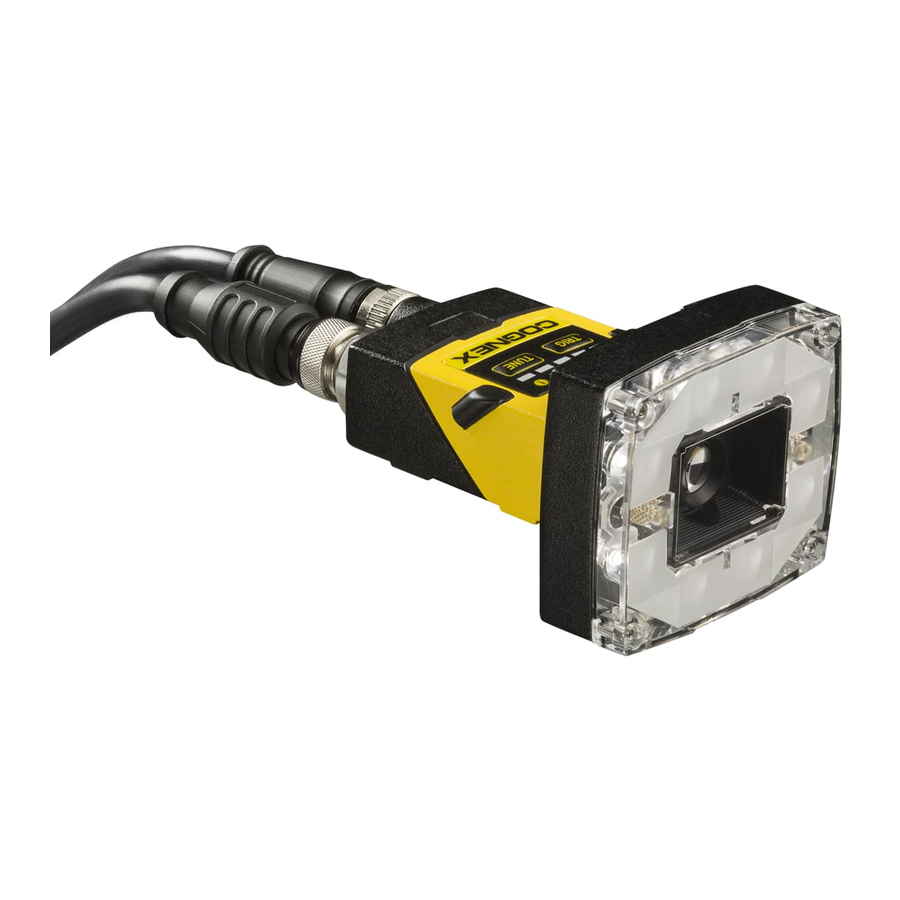
The In-Sight Explorer Help and EasyBuilder Help files, provided with In-Sight Explorer software. On-demand training: http://www.cognex.com/on-demand-training.aspx. The In-Sight online support site: http://www.cognex.com/Support/InSight. Standard Components The vision sensor consists of three main parts: 1. Optics module, featuring high brightness white LED ring light and 8mm lens 2. -
Page 9: Options And Accessories
Introduction Options and Accessories LENSES Lens, M12, 3.6mm (LM12-03-01) Lens, M12, 6 mm (LM12-06-01) Lens, M12, 8 mm (LM12-08-01) Lens, M12, 12 mm (LM12-12-01) Lens, M12, 16 mm (LM12-16-01) Lens, M12, 25 mm (LM12-25-01) Lens Spacer, M12, 16 mm (LM12-SPACER-16-0) Lens Spacer, M12, 25 mm (LM12-SPACER-25-01) FILTERS AND LIGHT COVER In-Sight 2000, Polarizer (IMPF-2000-POLAR) - Page 10 Introduction POWER SUPPLY Cognex 24 Volt DC Power Supply (ACC-24I) North America Power Cord (CBLI-24VDUS) Japan Power Cord (CBLI-24VDJP) United Kingdom Power Cord (CBLI-24VDUK ) Europe Power Cord (CBLI-24VDEU) MOUNTING BRACKETS Universal Mounting Bracket (BKT-2000-UNIV-000) Pivot Mounting Bracket (BKT-2000-PIVOT-00) Flat Surface Mounting Plate Adapter (BKT-2000-ADAPT-00)
-
Page 11: Installation
Cognex sales representative. Note: Cables are sold separately. If any of the standard components appear to be missing or damaged, immediately contact your Cognex Authorized Service Provider (ASP) or Cognex Technical Support. CAUTION: All cable connectors are “keyed”... -
Page 12: Indicator Leds
Installation Indicator LEDs Type Signal Color Meaning Status Power GREEN Power ON Trigger ORANGE (blink) Triggering Error Error Pass/fail indicator GREEN Pass Action Fail Network YELLOW Link up ORANGE (blink) Data transfer... -
Page 13: Sensor Mounting Configuration
Installation Sensor Mounting Configuration Perform the following steps to change between in-line and right-angle configuration. Note: Switching between in-line and right-angle configuration is recommended only up to 10 times in the lifetime of the vision sensor. Disconnect the vision sensor from power before changing the orientation. WARNING: Make sure that no electrostatic charges are applied to the PCB. - Page 14 Installation 5. Reinstall the washers and loosely fasten the modules together with the two T10 cap nuts, but do not tighten. 6. After each cap nut has been fastened, torque to 0.12 Nm (1.06 in-lb) and reinstall the screw covers. Note: There are unique left and right screw covers.
-
Page 15: Mount The Vision Sensor
Installation Mount the Vision Sensor Mounting the vision sensor at a slight angle (15°) can reduce image glare and improve inspection performance. In-line Configuration Use the universal mounting bracket (BKT-2000-UNIV-000) with the mounting holes on the I/O connector module. Right-Angle Configuration... -
Page 16: Connect The Ethernet Cable
Installation Connect the Ethernet Cable 1. Connect the Ethernet cable’s M12 connector to the vision sensor’s Ethernet connector. 2. Connect the Ethernet cable’s RJ-45 connector to a switch/router or PC, as applicable. Connect the Power and I/O Breakout Cable Note: Unused bare wires can be clipped short or tied back using a tie made of non-conductive material. Keep all bare wires separated from the +24VDC wire. -
Page 17: Set The Focus Position
Installation Set the Focus Position Adjust the focus on the back of the light module. Turn the screw clockwise to focus at a shorter distance, and counter- clockwise to focus at a longer distance. Working Distance and Field of View The distance from the vision sensor lens to the part that needs to be inspected is the working distance. - Page 18 Installation The following chart shows the horizontal field of view for In-Sight 2000-120/130 model vision sensors with 640 x 480 image resolution in 2X Image Magnification mode. The following chart shows the horizontal field of view for In-Sight 2000-130 vision sensor with 800 x 600 image resolution (2X Image Magnification mode).
-
Page 19: Replace The M12 Lens (Optional)
Installation Replace the M12 Lens (Optional) 1. Verify that the 24VDC power supply being used is unplugged and not receiving power. 2. Remove the four screws and the front cover from the optics module. 3. Move the lens to the furthest out position by turning the screw on the back of the light module clockwise. 4. - Page 20 Installation 6. Reattach the front cover. Tighten all four screws using a torque wrench; the maximum torque is 0.2 Nm (1.77 in- lb). 7. Restore power to the 24VDC power supply and turn it on if necessary.
-
Page 21: Install The Lens Filter (Optional)
Installation Install the Lens Filter (Optional) Lens filters can be used to increase the contrast of images and improve the ability of the vision sensor to distinguish desired characteristics. Lens filters are available for purchase as an accessory. 1. Verify that the 24VDC power supply being used is unplugged and not receiving power. 2. - Page 22 Installation 6. Reattach the front cover. Tighten all four screws using a torque wrench; the maximum torque is 0.2 Nm (1.77 in- lb). 7. Restore power to the 24VDC power supply and turn it on if necessary.
-
Page 23: Change The Led Ring Light (Optional)
Installation Change the LED Ring Light (Optional) 1. Verify that the 24VDC power supply being used is unplugged and not receiving power. 2. Remove the four screws and the front cover from the optics module. 3. Using a screwdriver, loosen the two screws on the LED ring light. 4. - Page 24 Installation 5. Carefully align the connector on the back of the new LED ring light with the pins on the vision sensor. Gently press down the LED ring light to the optics module. 6. Using a screwdriver, tighten the screws until they stop turning. 7.
-
Page 25: Specifications
Specifications Specifications The following sections list general specifications for the In-Sight 2000 series vision sensors. Vision Sensor Specifications 2000-110 2000-130 Specifications 2000-120 Minimum Firmware In-Sight version 5.2.1 Requirement Job/Program Memory 32MB non-volatile flash memory; unlimited storage via remote network device... - Page 26 Specifications 2000-110 2000-130 Specifications 2000-120 Maximum Humidity < 95%, non-condensing Protection IP65 when all connectors are attached to cables or shielded by a sealing cap Shock (Shipping and Storage) IEC 60068-2-27: 1000 shocks, semi-sinusoidal, 11g, 10ms IEC 60068-2-6: vibration test in each of the three main axis for 2 hours @ 10 Gs (10 to Vibration (Shipping and 500 Hz at 100m/s2 /15mm) Storage)
-
Page 27: I/O Specifications
Specifications I/O Specifications Cable and connector specifications and connection examples for acquisition trigger input and high-speed outputs are provided in the following sections. Acquisition Trigger Input The vision sensor features one acquisition trigger input that is opto-isolated. The acquisition trigger input can be configured to trigger from either an NPN (current sinking) or PNP (current sourcing) device. -
Page 28: High-Speed Outputs
Specifications High-Speed Outputs The high-speed outputs can be used as either NPN (pull-down) or PNP (pull-up) lines. Specification Description Voltage 28VDC maximum through external load Current 50mA maximum sink current OFF state leakage current 100µA External load resistance 240 Ohms to 10K Ohms Each line rated at a maximum 50mA, protected against over-current, short circuits and transients from switching inductive loads. -
Page 29: High-Speed Output Wiring
Specifications High-Speed Output Wiring Note: For more information, refer to Power and I/O Breakout Cable Specifications on page 30. To connect to an NPN-compatible PLC input, connect any of the high-speed outputs directly to the PLC input. When enabled, the output pulls the PLC input down to less than 3VDC. To connect to a PNP-compatible PLC input, connect any of the high-speed outputs directly to the PLC input. -
Page 30: Power And I/O Breakout Cable Specifications
Specifications Power and I/O Breakout Cable Specifications The Power and I/O Breakout cable provides connections to an external power supply, the acquisition trigger input, a general-purpose input, high-speed outputs, and RS-232 serial communications. Pin# Signal Name Wire Color HS OUT 2 Yellow RS-232 Tx White/Yellow... -
Page 31: Ethernet Cable Specifications
Specifications Ethernet Cable Specifications The Ethernet cable provides Ethernet connection for network communications. The Ethernet cable can be connected to a single device or provide connections to multiple devices via a network switch or router. Note: Cables are sold separately. The wiring for this cable follows standard industrial Ethernet M12 specifications. This differs from the 568B standard. -
Page 32: Dimensional Drawings
Specifications Dimensional Drawings The size of the vision sensor in the straight configuration is shown in the following figure: The size of the vision sensor in the angled configuration is shown in the following figure:... -
Page 33: Cleaning/Maintenance
Cleaning/Maintenance Cleaning/Maintenance Clean the Vision Sensor Housing To clean the outside of the vision sensor housing, use a small amount of mild detergent cleaner or isopropyl alcohol on a cleaning cloth. Do not pour the cleaner directly onto the vision sensor housing. CAUTION: Do not attempt to clean any In-Sight product with harsh or corrosive solvents, including lye, methyl ethyl ketone (MEK) or gasoline. - Page 34 P/N INS-597-0067-01 Rev. A...
Need help?
Do you have a question about the In-Sight 2000 Series and is the answer not in the manual?
Questions and answers