Table of Contents
Advertisement
Advertisement
Table of Contents

Subscribe to Our Youtube Channel
Related Manuals for Cognex Checker 4G Series


Summary of Contents for Cognex Checker 4G Series
- Page 1 COGNEX ® Checker ™ ® Quick Start Guide...
-
Page 2: Table Of Contents
Table of Contents Table of Contents . . . . . . . . . . . . . . . . . . . . . . . . . . . . . . . . . . 3 Checker 4G Accessories . -
Page 3: Checker 4G Accessories
Checker 4G Accessories Encoder-Compatible Right- Polarizing Window Power and I/O Cable Illumination Modules (CKR-xxxL-00) Angle Cable (CKR-4G-CBL- (CKR-WINDOW-POL) Red (CKR-RDRL-00), green (CKR- RT-002) (CKR-4G-CBL-001) GNRL-00), IR (CKR-IRRL-00), or UV Replacement lens cover (CKR-UVRL-00) lighting . Power and I/O extension cable with optical polarizer pre- with low-profile right-angle installed . -
Page 4: Checker 4G Overview
Checker 4G Overview Dimensions, Connectors, Indicators The Checker 4G sensor provides direct discrete I/O and power connections as well as Ethernet Mounting holes (M4 x 4 mm) connections to PCs and networked PLCs . Focus lock (M3, use 2 .5 mm hex key) Lens cover/focus ring Ethernet Traffic Indicator: Green: Link present... -
Page 5: Getting Started
PC • Create and save a job . Start the Checker software (on Windows 7, select All Programs -> Cognex -> 5 . Connect to and configure Checker Vision Sensors 4.1 -> Checker 4.1 from the Windows Start menu) . -
Page 6: Checker User Interface
Checker User Interface Menu bar and status pane . The menu bar lets you open and save jobs and manage Checker personalities and system settings . The status pane shows which Checker is connected, the Job name and if it has been saved, along with results for the most recent image . -
Page 7: Connecting To Checker
Connecting to Checker Adding a Checker to the Checkers List When the Get Connected step is selected, the Checker PC software displays all available Checker sensors detected on the subnet to which the PC is connected in the Checkers list . You can select any of these Checker sensors and click Connect to connect . -
Page 8: Configuring Checker
Configuring Checker The following list summarizes the items the Checker Configuration dialog lets you configure for your • In the Protocol Settings pane, select the Factory Floor Protocol (FFP) that should be Checker: enabled for use by Checker when communicating with the PLC. ProfiNET, EtherNet/IP, and a Generic FFP are available . -
Page 9: Part Trigger
Part Trigger A part trigger tells Checker that a part is ready to be inspected . Checker supports three trigger types . Internal Part Trigger: Checker uses its Part Finding Sensor to detect when a part is present and ready to be inspected. You create and configure the Part Finding Sensor by selecting a feature on your part that is always present . -
Page 10: Part Finding Sensors
Part Finding Sensors A Part Finding Sensor detects and locates your part in the image . You can create a Part Finding Sensor by Part Finding Sensors and Trigger Types drawing a box around a feature of part that is present on both good and bad parts . Part Finding Sensors are used differently for different trigger types . -
Page 11: Presence Sensors
Presence Sensors Sensor Threshold Presence Sensors evaluate a part of a Checker image to determine if a feature is present or not . Presence sensors support one-click setup; simply click on the feature you want to check to create and configure the The sensor threshold slider sets the level below which a sensor fails and above which a sensor sensor in a single step . -
Page 12: Presence Sensors
Presence Sensors Brightness sensors have the Brightness Range and Contrast sensors have the Sensitivity controls that let Color sensor has the Count Meter and Color Samples controls that let you tune the sensors to you tune the sensors to maximize the reported difference between good and bad parts . maximize the reported difference between good and bad parts . -
Page 13: Presence Sensors
Presence Sensors Edge Pattern sensor has the Match Meter and Sensitivity controls that let you tune the sensors to maximize the reported difference between good and bad parts . Match Meter: Features matching the training image with a score less than this fail . This page is left blank intentionally . -
Page 14: Measurement Sensors
Measurement Sensors Measurement Sensors evaluate part of a Checker image to determine if a feature is within a specified size Using the Measurement Sensor Controls range . Measurement sensors support one-click setup; simply click on the center of the feature you want to measure to create and configure the sensor in a single step. -
Page 15: Position Sensors
Position Sensors Position Sensors evaluate part of a Checker image to determine if the position and orientation of patterns, If the feature (pattern, object, or edge) to be inspected falls completely within the Sensor Pass/ objects, or edges are within specified ranges. Position sensors support one-click setup; simply click on the Fail Region of the sensor, position verification will pass. -
Page 16: Position Sensor Controls
Position Sensor Controls Sensor Pass/Fail Region: For all position sensors . Use this region to specify the positional pass region for a sensor . The feature the sensor is monitoring must be within this region to be considered a passing feature . Drag Bar: For the Edge position sensor . -
Page 17: Filmstrip Control
Filmstrip Mode Selector Filmstrip Control The Filmstrip Control lets you record and play back Checker images . The Filmstrip mode selector controls whether the Filmstrip is recording or playing back images, and if it is recording, when images are recorded to the Filmstrip . Video mode . -
Page 18: Power And I/O Connector
Power and I/O Connector Power, Trigger, and Output Wiring Checker I/O can be configured in software for Job Change or Encoder mode. Lead Color Job Change I/O Encoder I/O Power Mode Mode 24 VDC+ POWER IN (RED) 24 VDC + 24 VDC + 24 VDC –... -
Page 19: Wiring An External Retrain Line
Wiring an External Retrain Line Wiring a Job Change Signal You can configure both Part Finding Sensors and Inspection Pattern Sensors to be retrainable by checking Checker 4G has 32 Job slots . You can assign saved Checker Jobs to Job slots, then load them External Retrain in the sensor control panel . -
Page 20: Wiring An Encoder
ENCODER − − ENCODER − Wiring an Encoder Checker I/O Circuits B– A– If your Checker 4G is configured for encoder input, you can connect both differential and single-ended Discrete encoders . Using an encoder allows you to specify input and output delay values in pulse counts instead of Inputs 5-24 VDC real time units . -
Page 21: Mounting Checker
Mounting Checker The optional Checker mounting bracket lets you easily position and adjust Checker on your Caution: Do not use a mounting screw with an exposed thread depth of greater than line . 3.5mm. Allowing the mounting screw to bottom in the mounting hole can damage Checker. -
Page 22: Working Distance And Fov (Checker 4G1)
Working Distance and FOV (Checker 4G1) Working Distance and FOV (Checker 4G1) The distance from Checker’s lens cover to your part is the working distance; the field of view is what Checker can see at that distance. As the working distance increases, so does the size of the field of view. These charts show the field of view provided by the standard 5.8mm lens at various working distances, as well as the fields of view provided by the lenses included in the optional Checker Lens Kit (CKR-200- LENSKIT) . -
Page 23: Working Distance And Fov (Checker 4G7/4G7X)
Working Distance and FOV (Checker 4G7/4G7x) Working Distance and FOV (Checker 4G7/4G7x) Field of View (in) Field of View (cm) 3.6 mm 3.6 mm 5.8 mm 5.8 mm 8 mm 8 mm 16 mm 16 mm 25 mm 25 mm Working Distance (cm) Working Distance (in) 44 Checker 4G Quick Start Guide... -
Page 24: Working Distance And Fov (Checker 4G7C)
Working Distance and FOV (Checker 4G7C) Working Distance and FOV (Checker 4G7C) Field of View (in) Field of View (cm) 3.6 mm 3.6 mm 5.8 mm 5.8 mm 8 mm 8 mm 16 mm 16 mm 25 mm 25 mm Working Distance (in) Working Distance (cm) 46 Checker 4G Quick Start Guide... -
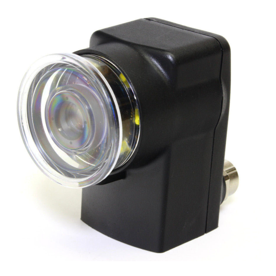
Page 25: Adjusting Focus
Adjusting Focus Adjust focus using the clear ring on Checker . Using the supplied 2 .5 mm hex key, you can lock the focus adjustment by tightening the focus lock . The lens cover both seals the front of Checker and lets you adjust the lens focus . -
Page 26: Changing Lenses
Changing Lenses Installing and Removing Filters and Lights To remove the Checker lens, follow the steps listed below . To replace Checker’s built-in lighting module, first remove the lens and lens cover, as described in steps 1-2 on the preceding page, then follow the steps listed below . 1 . -
Page 27: Specifications And Precautions
Connect the cable shield to earth ground . Operating humidity: 0% - 90% non-condensing • A Cognex-supplied, IP67-rated M12 Ethernet cable must be fitted to the Ethernet con- Maximum operating altitude: 4000 meters nector for Checker to meet the IP67 protection standard . - Page 28 . Copyright © 2014 Cognex Corporation All Rights Reserved . This document may not be copied in whole or in part, nor transferred to any other media or language, without the written permission of Cognex Corporation . Cognex, the Cognex logo, Checker, and the Checker logo are trademarks, or registered trademarks, of Cognex Corporation .
Need help?
Do you have a question about the Checker 4G Series and is the answer not in the manual?
Questions and answers