
Subscribe to Our Youtube Channel
Related Manuals for Unigas R1030


Summary of Contents for Unigas R1030
- Page 1 R1025 R1030 R1040 Gas burners Progressive / Fully modulating MANUAL OF INSTALLATION - USE - MAINTENANCE BURNERS - BRUCIATORI - BRULERS - BRENNER - QUEMADORES - ГОРЕЛКИ M03996CI Rel. 8.1 03/2015...
-
Page 2: General Introduction
DANGERS, WARNINGS AND NOTES OF CAUTION THIS MANUAL IS SUPPLIED AS AN INTEGRAL AND ESSENTIAL PART OF THE PRODUCT AND MUST BE DELIVERED TO THE USER. INFORMATION INCLUDED IN THIS SECTION ARE DEDICATED BOTH TO THE USER AND TO PERSONNEL FOLLOWING PRO- DUCT INSTALLATION AND MAINTENANCE. -
Page 3: Directives And Standards
DIRECTIVES AND STANDARDS do not leave the equipment exposed to weather (rain, sun, etc.) unless expressly required to do so; Gas burners European directives: do not allow children or inexperienced persons to use equipment; - Directive 2009/142/EC - Gas Appliances; The unit input cable shall not be replaced by the user. -
Page 4: Symbols Used
-EN 55014-1Electromagnetic compatibility - Requirements for household appliances, electric tools and similar apparatus. -UNI EN 676 (Gas Burners; -CEI EN 60335-1(Household and similar electrical appliances - Safety. Part 1: General requirements; - EN 50165 Electrical equipment of non-electric appliances for household and similar purposes. -
Page 5: General Features
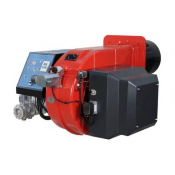
PART I: SPECIFICATIONS PART I: SPECIFICATIONS 1.0 GENERAL FEATURES Note: the figure is indicative only Control panel with startup switch Gas train Electrical panel Cover Blast tube + Combustion head Flange Silencer Adjusting cam Actuator 10 Air pressure switch 11 Combustion head adjusting ring nut Gas operation: the gas coming from the supply line, passes through the valves group provided with filter and stabiliser. -
Page 6: Burner Model Identification
Burners are identified by burner type and model. Burner model identification is described as follows. Type R1025 Model MD. S. BURNER TYPE R1025, R1030, R1040 FUEL M - Natural gas L - LPG OPERATION (Available versions) PR - Progressive MD - Fully modulating... - Page 7 PART I: SPECIFICATIONS R1025 R1030 R1030 R1040 BRUCIATORE TIPO L-..1.xx L-..1.65 L-..1.xx L-..1.xx 2550 - 8700 2550 - 9500 2550 - 10600 2550 - 13000 Output min - max kW Fuel Gas category 3B/P 95 - 325 95 - 355...
- Page 8 100 1852 377 30 854 145 542 664 1310 680 2057 1235 822 400 450 520 709 660 831 M16 651 460 460 848 204 269 644 80 1092 350 1161 379 330 R1030 65 1890 377 30 826 117 542 657 1348 680 2038 1216 822 454 504 520 709 660 831 M16 651 460 460 922 204 269 718 80 1092 289 1161 372 330...
- Page 9 PART I: SPECIFICATIONS 1.5 How to read the burner “Performance curve” To check if the burner is suitable for the boiler to which it must be instal- Campo di lavoro bruciatori lled, the following parameters are needed: Tipo P60 Mod. M-xx.x.IT.A.0.50 - M-.xx.x.IT.A.0.65 furnace input, in kW or kcal/h (kW = kcal/h / 860);...
-
Page 10: Performance Curves
PART I: SPECIFICATIONS 1.7 Performance Curves R1025 ..1.xx R1030 ...1.65 R1030 ..1.xx R1040 ...1.xx To get the input in kcal/h, multiply value in kW by 860. Data are referred to standard conditions: atmospheric pressure at 1013mbar, ambient temperature at 15°C NOTE: The performance curve is a diagram that represents the burner performance in the type approval phase or in the laboratory tests, but does not represent the regulation range of the machine. - Page 11 PART I: SPECIFICATIONS 1.8 Pressure in the Network / gas flow rate curves (natural gas) R1025 M-..1.xx Gas rate Stm R1030 M-..65 R1030 M-..1.xx Gas rate Stm Gas rate Stm R1040 M-. Gas rate Stm Caution: the gas rate value is quoted on the x-axis, the related network pressure is quoted on the y-axis (pressure value in the combustion chamber is not included).
- Page 12 PART I: SPECIFICATIONS 1.9 Combustion head gas pressure curves depending on the flow rate The curves referred to the gas pressure in the combustion head, depending on the gas flow rate, are referred to the burner properly adjusted (percentage of residual O in the flues as shown in the “Recommended combustion values”...
- Page 13 PART I: SPECIFICATIONS 1.11 Pressure - rate in combustion head curves (natural gas) Curves are referred to pressure = 0mbar in the combustion chamber! R1025 M-.. Gas rate Stm R1030 M-.. R1040 M-.. Gas rate Stm Gas rate Stm...
- Page 14 PART II: INSTALLATION PART II: INSTALLATION 2.0 MOUNTING AND CONNECTING THE BURNER 2.1 Packing The burners are despatched in wooden crates whose dimensions are: 2280 x 1730 x 1360 (L x P x H) Packing cases of this type are affected by humidity and are not suitable for stacking. The following are placed in each packing case: burner with detached gas train;...
- Page 15 PART II: INSTALLATION Keys Burner Fixing nut Washer Ceramic fibre plait Stud bolt Blast tube 2.4 Matching the burner to the boiler The burners described in this manual have been tested with combustion chambers that comply with EN676 regulation and whose dimensions are described in the diagram .
- Page 16 PART II: INSTALLATION 3.0 GAS TRAIN CONNECTIONS The diagrams show the components of the gas trai included in the delivery and which must be fitted by the installer.The diagrams are in compliance with the current laws. ATTENTION: BEFORE EXECUTING THE CONNECTIONS TO THE GAS PIPE NETWORK, BE SURE THAT THE MANUAL CUTOFF VALVES ARE CLOSED.
- Page 17 PART II: INSTALLATION ATTENTION: it is recommended to mount filter and gas valves to avoid that extraneous material drops inside the valves, during maintenance and cleaning operation of the filters (both the filters outside the valves group and the ones built-in the gas valves). The procedures of installation fo the gas valves are showed in the next paragraphs, according to the gas train used: threaded gas trains with Siemens VGD20..
- Page 18 PART II: INSTALLATION 0 - 22 15 - 120 100 - 250 Performance range (mbar) neutral yellow Spring colour Once the gas train in installed, execute the electrical connections for all its items (gas valves group, gas proving system, pressure switches).
- Page 19 PART II: INSTALLATION connection to the gas supply network Once the gas train in installed, execute the electrical connections for all its items (gas valves group, pressure switch). ATTENTION: once the gas train is mounted according to the diagram on Fig. 11, the gas proving test mus be per- formed, according to the procedure set by the laws in force.
- Page 20 PART II: INSTALLATION Integrated proving system (burners equipped with LME7x, LMV, LDU) This paragraph describes the integrated proving system operation sequence: At the beginning both the valves (EV1 and EV2) must be closed. Test space evacuating: EV1 valve (burner side) opens and keep this position for a preset time (td4), in order the bring the test space to ambient pressure.Test atmospheric pressure: EV1 closes and keep this position for a preset time (test time td1).
-
Page 21: Electrical Connections
PART II: INSTALLATION 4.0 ELECTRICAL CONNECTIONS WARNING! Respect the basic safety rules. make sure of the connection to the earthing system. do not reverse the phase and neutral connections. fit a differential thermal magnet switch adequate for connection to the mains. - Page 22 PART III: OPERATION PART III: OPERATION WARNING: before starting the burner up, be sure that the manual cutoff valves are open and check that the pres- sure upstream the gas train complies the value quoted on paragraph “Technical specifications”. Be sure that the mains switch is closed.
-
Page 23: Gas Operation
PART III: OPERATION Fig. 13 - Burner control panel Keys Main switch Reset pushbutton for control box CMF switch (0=stop, 1=low flame, 2=high flame, B2 B3 3=automatic) - fully modulating burners only Lock-out LED Hi-flame operation LED Lo-flame operation LED “Ignition transformer operation”... - Page 24 PART III: OPERATION AIR FLOW AND FUEL ADJUSTMENT WARNING! During commissioning operations, do not let the burner operate with insufficient air flow (danger of formation of carbon monoxide); if this should happen, make the fuel decrease slowly until the normal combustion values are achieved.
- Page 25 PART III: OPERATION Siemens VGD.. To adjust the air flow rate in the high flame stage, loose the RA nut and screw VRA as to get the desired air flow rate: moving the rod TR towards the air damper shaft, the air damper opens and consequently the air flow rate increases, moving it far from the shaft the air damper closes and the air flow rate decreases.
- Page 26 PART III: OPERATION 5.3 Fully-modulating burners .To adjust the fully-modulating burners, use the CMF switch on the burner control panel (see next picture), instead of the TAB thermo- stat as described on the previous paragraphs about the progressive burners. Go on adjusting the burner as described before, paying attention to use the CMF switch intead of TAB.
- Page 27 PART III: OPERATION if the maximum pressure switch is mounted upstreaam the gas valves: measure the gas pressure in the network, when flame is off; by means of the adjusting ring nut VR, set the value read, increased by the 30%. if the maximum pressure switch is mounted downstream the “gas governor-gas valves”...
- Page 28 V screws that fix the adjusting plate D; insert a screwdriver on the adjusting plate notches and let it move CW/CCW as to open/close the holes; once the adjustmet is performed, fasten the V screws. R1025 - R1030 R1040 open holes...
-
Page 29: Routine Maintenance
PART IV: MAINTENANCE PART IV: MAINTENANCE At least once a year carry out the maintenance operations listed below. In the case of seasonal servicing, it is recommended to carry out the maintenance at the end of each heating season; in the case of continuous operation the maintenance is carried out every 6 months. - Page 30 PART IV: MAINTENANCE 6.2 Replacing the spring in the gas valve group To replace the spring in the gas valve group,proceed as follows: Carefully twist the protection cap 1 and the O-ring 2. remove the “set value” spring 3 from housing 4. Replace spring 3.
-
Page 31: Adjusting The Ignition Electrode
PART IV: MAINTENANCE 6.4 Adjusting the ignition electrode ATTENTION: avoid the electrode to get in touch with metallic parts (blast tube, head, etc.), otherwise the boiler operation would be compromised. Check the electrode position after any intervention on the combustion head. Fig. - Page 32 PART IV: MAINTENANCE 6.5 Replacing the ignition electrode ATTENTION: avoid the electrode to get in touch with metallic parts (blast tube, head, etc.), otherwise the boiler operation would be compromised. Check the electrode position after any intervention on the combustion head. To replace the ignition electrode, proceed as follows: remove the burner cover disconnect the electrode (E) cable (CE);...
-
Page 33: Seasonal Stop
PART IV: MAINTENANCE 6.8 Seasonal stop To stop the burner in the seasonal stop, proceed as follows: turn the burner main switch to 0 (Off position) disconnect the power mains close the fuel valve of the supply line 6.9 Burner disposal In case of disposal, follow the instructions according to the laws in force in your country about the “Disposal of materials”. -
Page 34: Wiring Diagrams
PART IV: MAINTENANCE 7.0 WIRING DIAGRAMS Refer to the attached wiring diagrams. WARNING 1 - Electrical supply 230V 50Hz 1 a.c./400V 50Hz 3N a.c. 2 - Do not reverse phase with neutral 3 - Ensure burner is properly earthed... -
Page 35: Troubleshooting
TROUBLESHOOTING TROUBLE CAUSE MAIN SWITCH OPEN LACK OF GAS MAXIMUM GAS PRESSURE SWITCH DEFECTIVE THERMOSTATS/PRESSURE SWITCHES DEFECTIVES OVERLOAD TRIPPED INTERVENTION AUXILIARIES FUSE INTERRUPTED DEFECTIVE CONTROL BOX DEFECTIVE ACTUATOR AIR PRESSURE SWITCH FAULT OR BAD SETTING MINIMUM GAS PRESSURE SWITCH DEFECTIVE OR GAS FILTER DIRTY IGNITION TRANSFORMER FAULT IGNITION ELECTRODES BAD POSITION... -
Page 36: Burner Exploded View
BURNER EXPLODED VIEW... -
Page 37: Ignition Electrode
ITEM DESCRIPTION ITEM DESCRIPTION ITEM DESCRIPTION AIR INLET CONE INDEX LABEL 13.2.1 FRONT CONTROL PANEL SPACER AIR DAMPER INDEX 13.2.2 LIGHT BUTTERFLY VALVE ASS.Y GAS PRESSURE 13.2.3 LIGHT PHOTOCELL GAS SOLENOID VALVE 13.2.4 LOCK-OUT RESET BUTTON PLATE GAS GOVERNOR WITH FILTER 13.2.5 PROTECTION LEVERAGE... - Page 40 C.I.B. UNIGAS S.p.A. Via L.Galvani, 9 - 35011 Campodarsego (PD) - ITALY Tel. +39 049 9200944 - Fax +39 049 9200945/9201269 web site: www.cibunigas.it - e-mail: cibunigas@cibunigas.it Note: specifications and data subject to change. Errors and omissions exceptd.
Need help?
Do you have a question about the R1030 and is the answer not in the manual?
Questions and answers