Table of Contents
Advertisement
Quick Links
Advertisement
Table of Contents

Subscribe to Our Youtube Channel
Related Manuals for AIMS Power PIGRID250


Summary of Contents for AIMS Power PIGRID250
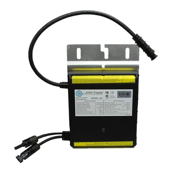
- Page 1 MICRO-INVERTER PIGRID250 250W MICRO GRID TIED INVERTER 208, 220, 230, 240VAC...
-
Page 2: Table Of Contents
TECHNICAL MANUAL CONTENTS INTRODUCTION ------------------------------------------------------------------------------ 3 SAFETY ------------------------------------------------------------------------------------------ 4 SYMBOL ILLUSTRATION -------------------------------------------------------------- 4 INSTALLATION WARNINGS ----------------------------------------------------------- 4 PREPARE FOR INSTALLING ------------------------------------------------------------- 6 TRANSPORTION AND INSPECTION ------------------------------------------------ 6 CHECK INSTALLATION ENVIRONMENT ---------------------------------------- 8 INSTALLATION POSITION ------------------------------------------------------------- 8 CHOOSE AC CABLE ---------------------------------------------------------------------- 9 MOUNTING AND WIRING --------------------------------------------------------------- 10 INSTALLATION DIAGRAM ----------------------------------------------------------- 10 ASSEMBLY INSTRUCTIONS ---------------------------------------------------------- 13... -
Page 3: Introduction
Micro-inverter under the guide of this document. PIGRID250 is a 250W maximum Grid Tied Micro-inverter, and is designed to operate on 208Vac, 220Vac, 230Vac or 240Vac split phase AC grid connections. -
Page 4: Safety
INSTALLATION WARNINGS The PIGRID250 Micro-inverter is designed and tested according to international safety requirements (UL 1741/IEEE 1547). However, certain safety precautions must be taken when installing and operating this inverter. The installer must read and follow all instructions, cautions... - Page 5 Overcurrent Protection Devices (OCPD). AIMS Power DOES NOT provide AC output overcurrent protection. To reduce the risk of fire, connect only to a circuit with 20A maximum branch circuit overcurrent protection in accordance with the National Electric Code (ANSI/NFPA 70) ...
-
Page 6: Prepare For Installing
Micro-inverter, it is necessary to check the container for any external damage and verify receipt of all items. Call AIMS Power, the Shipper or the carrier immediately if damage or shortage is detected. If inspection reveals damage to the inverter, contact the supplier, or authorized distributor for a repair/return determination and instructions regarding the process. - Page 7 Table 2 Code Description AC trunk spool_41inches_50plugs AC cable (4conducotors) 10AWG Plug inches 41 AC trunk spool_67inches_32plugs AC cable (4conducotors) 10AWG Plug inches 67 AC cable (4conducotors) AC trunk spool_81inches_27plugs 10AWG Plug inches 81 Insulated AC cap for AC cable connectors AC trunk plug cap AC trunk end cap End cap for 10 AWG AC cable...
-
Page 8: Check Installation Environment
CHECK INSTALLATION ENVIRONMENT Installation of the equipment is carried out based on the system design and the place in which the equipment is installed. The installation must be carried out with the equipment disconnected from the grid (power disconnect switch open) and with the photovoltaic modules shaded or isolated. ... -
Page 9: Choose Ac Cable
PV Module Micro Inverter Fig.1. Installation position of Micro-inverter CHOOSE AC CABLE The AC cable is shipped on a reel with the connectors pre-mounted. The available spacing between connectors is: 41”, 67”, and 81”. The installer is responsible for choosing the AC cable model with the correct spacing on the basis of the orientation (shown below) and type of photovoltaic modules. -
Page 10: Mounting And Wiring
AC-TRUNK Spool 41 Inches 50 Plugs 72 Cells AC-TRUNK Spool 67 Inches 32 Plugs 60 Cells AC-TRUNK Spool 81 Inches 27 Plugs 72 Cells * Note: The AC-TRUNK SPOOL may contain a number of connectors indicated by the number of plugs in the part number. - Page 11 Red: L1 PV Model Black: L2 White: Neutral … Green: Ground Micro Inverter AC Cable Junction … Distribution Panel … Fig.2. 208Vac three phase Red: L1 PV Model Black: L2 White: Neutral … Green: Ground Micro Inverter AC Cable Distribution Panel Junction Fig.3.
- Page 12 Assembly Diagram AC Trunk End Cap PV Module Micro Inverter AC Trunk Cable Plug Bracket DC Cables From PV Module Junction Fig.4. Assembly Illustration PV Module Junction AC drop cable AC drop cable Microinverter extension cable Fig.5. Assembly Illustration for one microinverter system...
-
Page 13: Assembly Instructions
ASSEMBLY INSTRUCTIONS Step 1. Wire AC Cable Wire the AC cable along the frame structure of photovoltaic modules. Bracket AC Trunk Cable Plug Fig.6. Wiring the AC cable Ensure that the cable matches the installation conditions, particularly in regards to the number of the modules and their orientation. The number of the Micro-inverters should not exceed the maximum number permitted for installation. -
Page 14: Step 3. Grounding The System
The Micro-inverter must be under the module, out of long-term exposure to direct sunlight or rain. Step 3. Grounding the System The system must be grounded according to local laws. The inverter can typically be earth grounded using the connector clamp secured to the chassis and an adequately- sized conductor. -
Page 15: Step 4. Fasten Ac Cable
Step 4. Fasten AC Cable Fasten the AC cable to the frame with cable ties or tie wraps. Each connector is provided with two slots for ideal fastening. If using nylon or materials that may decompose in sun light or over time, it is strongly recommended to inspect on occasion. Fig.8. - Page 16 AC Trunk Unlock Tool AC Trunk Cable Micro Inverter AC Temporary Plug Cap Drop Cable Fig.9. Connect AC Cable of Micro-inverter Fig.10. Connect AC Cable of Micro-inverter system The AC-TRUNK UNLOCK TOOL must be used for the disconnection of the AC connector from the MICRO inverter or for the removal of the AC-TRUNK PLUG CAP from the connectors on the ACTRUNK cable.
-
Page 17: Step 6. Protecting Unused Ends
AC Trunk Plug Cap AC Trunk Cable Temporary Plug Cap Fig.11. Unused Connectors Step 6. Protecting Unused Ends The unused ends of the AC-TRUNK cable must be terminated with the proper end. Fit the appropriate AC-TRUNK END CAP on the unused ends of the AC-TRUNK cable. AC Trunk End Cap Fig.12. - Page 18 All the external connections to the insulated junction box (caps, adapters, etc.) should be made with securely-sealed AIMS Power components. AIMS Power AC cables from the Micro-inverters have four conductors with different colors to identify the function of each conductor:...
-
Page 19: Step 8. Drawing System Map
Pay special attention and ensure not to reverse the phase (load lines) with the neutral! The installation technician is responsible for selecting a junction box with the appropriate dimensions and insulation. The installation technician is responsible for selecting a cable running between the junction box and the load distribution panel with the appropriate length and cross section. -
Page 20: Step 9. Install Photovoltaic Modules
Step 9. Install Photovoltaic Modules Install the photovoltaic modules, and connect the DC cables of the modules to the corresponding DC input side of the Micro-inverter. DC Cable From PV Module DC Cable From Micro Inverter Fig.15. Connect DC Cables The recommended installation requires keeping the Micro-inverters underneath the photovoltaic modules, so that the Micro-inverters can operate in the shade. -
Page 21: Maintenance Guide
MAINTENANCE GUIDE ROUTINE MAINTENANCE Only authorized personnel are allowed to carry out the maintenance operations and are responsible to report any anomalies. Always use personal protective equipment when working on or around power equipment. During normal operation, check that the environmental and logistical conditions are ... -
Page 22: Storage And Dismantling
For cleaning, DO NOT use rags made of filamentary material or corrosive products that may corrode parts of the equipment or generate electrostatic charges. Avoid temporary repairs. All repairs should be carried out using only genuine spare parts. STORAGE AND DISMANTLING If the equipment is not used immediately or is stored for long periods, check that it is ... -
Page 23: Appendix
APPENDIX TECHNICAL DATA Model PIGRID250 Input data(DC) Recommended PV module power (STC) range 200~310 MPPT voltage range (V) 27~48 Operating voltage range (V) 16~60 Maximum input voltage (V) Maximum input current (A) Maximum input source back feed current to input source (A) - Page 24 accuracy Frequency: +/- 0.1 Hz Alternate Trip Time +/- 50 ms Efficiency 96.5% Peak inverter efficiency 96.0% CEC weighted efficiency 99.9% Nominal MPPT efficiency Mechanical Data -40 ~ +65 Ambient temperature range (℃) -40 ~ +85 Operating temperature range (℃) Dimensions (W×H×D mm) 165×183×28 Weight (kg)
-
Page 25: Efficiency Curves
Voltage and frequency limits for utility Interaction Simulated utility source Maximum time (sec) (cycles) Condition at 60 Hz before cessation of Voltage (V) Frequency (Hz) current to the simulated utility < 0.50 V Rated 0.16 ≤ V < 0.88 V 0.50 V Rated 0.16-5... -
Page 26: Template For Map Of Micro-Inverter Installation
TEMPLATE FOR MAP OF MICRO-INVERTER INSTALLATION Customer Information: Please affix the extra label that comes from each inverter, on the appropriate position on this diagram. - Page 27 Red: L1 PV Model Black: L2 White: Neutral … Green: Ground Micro Inverter AC Cable Junction … Distribution Panel … 208Vac three phase...
- Page 28 Red: L1 PV Model Black: L2 White: Neutral … Green: Ground Micro Inverter AC Cable Distribution Panel Junction 240Vac split phase...
-
Page 29: Warranty Instructions
In no event shall AIMS be liable for indirect, special or consequential damages. This warranty only applies to AIMS Power branded products. All other name brand products are warranted by and according to their respective manufacturer. Please do not attempt to return non-AIMS Power branded products to AIMS Power.
Need help?
Do you have a question about the PIGRID250 and is the answer not in the manual?
Questions and answers