SIGLENT SDL1000X User Manual
Programmable dc electronic load
Hide thumbs
Also See for SDL1000X:
- Service manual (35 pages) ,
- Quick start manual (16 pages) ,
- Troubleshooting manual (7 pages)

Related Manuals for SIGLENT SDL1000X


Summary of Contents for SIGLENT SDL1000X
- Page 1 User Manual SDL1000X Programmable DC Electronic Load UM0801X-C01A 2019 SIGLENT TECHNOLOGIES CO., LTD...
- Page 2 SIGLENT TECHNOLOGIES CO., LTD. All rights reserved. Trademark Information SIGLENT is registered trademark of SIGLENT TECHNOLOGIES CO., LTD. Statement ● SIGLENT products are protected by patent laws in and outside of the P.R. China. ● SIGLENT reserves the right to change the specifications and price. ●...
-
Page 3: General Safety Summary
Inadequate ventilation may cause an increase of the internal temperature of the instrument, which can lead to damage. Please keep proper ventilation and check the fan and air-vents regularly when using the instrument. Operating conditions Location: Indoor, no direct sunlight, minimal interference and pollution SDL1000X User Manual III... - Page 4 Do not operate in an explosive atmosphere To avoid personal injury or damage to instrument, please do not operate in an explosive atmosphere. Keep surface of the product clean and dry Please keep the surface of the product clean and dry. SDL1000X User Manual IV...
-
Page 5: Safety Terms And Symbols
WARNING: Indicates potential injury or hazard that may happen. CAUTION: Indicates potential damage to the instrument or other property that may happen. Symbols that may appear on the product: Hazardous Protective Warning Earth Power Voltage Earth Terminal Ground Switch SDL1000X User Manual V... -
Page 6: Sdl1000X Brief Introduction
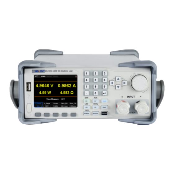
SIGLENT SDL1000X Brief Introduction The SDL1000X series Programmable DC Electronic Load has a 3.5 inch TFT-LCD display , a user-friendly interface and superb performance specifications. Two versions are available: The SDL1020X features an input range of 150 V/30 A with a total power of 200 W. The SDL1030X has an input range of with a total power of 300 W. - Page 7 OCP, OVP, OPP, OTP and LRV protections Wave form graphing Voltage based rise/fall function V and V function latch Smart fan control to minimize noise Remote control and measurement on PC SDL1000X User Manual VII...
-
Page 8: Table Of Contents
LED Test Function 54 Waveform Display Function Restore Function of Terminals on the Rear Panel Sense mode 63 External trigger function Voltage fault function 66 Current and voltage monitor Short-circuit monitor Protection Functions Overvoltage protection (OVP) 66 SDL1000X User Manual VIII... - Page 9 Turn ON/OFF the Sense Function 79 Turn ON/OFF SOF Function 79 Break-Over Volatge Turn ON/OFF Von-Latch Function 79 Set Trigger Set Aver 80 Set EXTC(External Interface) 81 SLMT 86 Limit I_Protect 87 P_Protect 88 Troubleshooting Contact SIGLENT 91 SDL1000X User Manual IX...
-
Page 11: Chapter 1 Start Guide
Chapter 1 Start Guide In this chapter, we introduce the front panel and display interface of the SDL1000X, and also tips for how to check and operate the digital load for the first time. The main content of Chapter 1 includes: ... -
Page 12: General Inspection
The consigner or carrier will be responsible for damage to the instrument resulting from shipment. SIGLENT will not provide free maintenance or replacement. 2. Inspect the instrument. -
Page 13: The Front Panel
Chapter 1 Start Guide SIGLENT The Front Panel Figure1: The front panel of the SDL1000X 1. LCD The load has a 3.5 inch TFT-LCD display which can display system parameter settings, system output state, wave forms, menu options, prompt messages, etc. - Page 14 SIGLENT Chapter 1 Start Guide 3. Function button and power key Press down the button to enter the constant current mode. Enter one of the dynamic modes (DYN mode) by pressing the shift button at the same time. Press down the button to enter constant voltage (CV) mode.
- Page 15 Chapter 1 Start Guide SIGLENT cursor to select the setting parameter. Input the number zero to nine using the keypad. Dot/Period Enter Softkey functions are define by the adjacent on-screen label 4. Input Terminal Physical input connections to the external circuit and voltage.
-
Page 16: The Rear Panel
SIGLENT Chapter 1 Start Guide The Rear Panel Figure 2: The rear panel of the SDL1000X 1. Warning message Warnings about grounding the instrument and other important information. 2. AC input voltage description The frequency and voltage of the AC power supply must match the specification of the fuse. - Page 17 Chapter 1 Start Guide SIGLENT The specified fuse must be rated for the input voltage (Please refer to the “ AC input voltage description”) 5. AC line power selection switch AC Input Voltage: 110/220 V 6. LAN interface Connect to the local network (LAN) using a standard RJ45 interface.
-
Page 18: Connect Power
SIGLENT Chapter 1 Start Guide Connect power The SDL1000X supports a variety of AC line power input values. For each line voltage, the rear panel voltage selector settings are different, as shown in table 1 below. Table 1: AC input line power specifications... - Page 19 Chapter 1 Start Guide SIGLENT 4. Connect the power Connect the instrument to AC power supply using the power cord provided in the accessories. Then press the button to turn on the electronic load. WARNING Before turning the instrument on, please disconnect the power supply and set the voltage selector to the appropriate value.
-
Page 20: User Interface
SIGLENT Chapter 1 Start Guide User interface Figure 3: The user interface of the SDL1000X 1. Channel output mode 2. Channel output state 3. Short state 4. Remote sense mode 5. LAN connection icon 6. USB connection icon 7. Remote mode... - Page 21 Chapter 1 Start Guide SIGLENT 9. Setting value 10. Measured output values 11. Voltage rise and fall time...
- Page 22 If the instrument fails, the self-test failure information will be displayed. If you encounter any problems or failures, please contact your nearst SIGLENT support office. CAUTION Ensure that the AC selector setting on the rear panel of the instrument matches the actual AC input voltage, otherwise, the electronic load could be damaged.
-
Page 23: Fuse Replacement
Chapter 1 Start Guide SIGLENT Fuse Replacement The specifications of the fuse are relative to the actual input line voltage shown in the table below. You also can refer to the rear panel “input power requirement”. Input voltage Fuse specification... -
Page 24: Chapter 2 Function And Features
OCPT Test Function OPPT Test Function Auto Test Function LED Test Function Waveform Display Function Store and Recall Rear Panel Terminal functions Short monitor function Protective function SDL1000X User Manual 14... -
Page 25: Local/Remote Operation Mode
Display key) will be disabled. This is known as “local lock out”. When locked, the instrument front panel is disabled and the load can only be controlled via programming commands. To return to the local operation mode, press the Shift key plus the Display key on the front panel. SDL1000X User Manual 15... -
Page 26: Static Operation Mode
Constant Current Mode Figure 2-1 Voltage-Current Relationship Schema under CC Mode Operating Steps 1. Turn off the instrument, as shown in Figure 2-2, connect the DUT and the channel input terminals on the front panel of the load. SDL1000X User Manual 16... - Page 27 Note: The load will begin to sink current only if the input voltage is greater than the conduction voltage of the system (default value is 0 V). SDL1000X User Manual 17...
-
Page 28: Constant Voltage (Cv) Mode
CC mode. Figure 2-4 Waveform display interface of CC Mode Constant Voltage (CV) Mode In CV mode, the electronic load will sink enough current to maintain the input voltage at the setpoint, as shown in Figure 2-5. SDL1000X User Manual 18... - Page 29 2. Press CV to enter the main interface of CV mode, as shown in Figure 2-6. Figure 2-6 CV Mode Main Interface 3. Set CV mode current range (5 A or 30 A) and voltage range (36 V SDL1000X User Manual 19...
- Page 30 When the input current changes, the load will apply a constant voltage. Press the Display key again to exit the waveform display interface and return to the main interface of CV mode. Figure 2-7 Waveform display interface of CV Mode SDL1000X User Manual 20...
-
Page 31: Constant Resistance (Cr) Mode
(-) terminal of the channel output. Incorrect polarity may cause damage to the instrument or the DUT. 2. Press CR to enter the main interface of CR mode, as shown in Figure 2-9. SDL1000X User Manual 21... - Page 32 Figure 2-10. By default, the resistance waveform is displayed. When the input voltage changes, the load current will linearly change. Press the Display key again to exit the waveform display interface and return to the main interface of CR mode. SDL1000X User Manual 22...
-
Page 33: Constant Power (Cp) Mode
Figure 2-11 Voltage-Current Relationship Schema under CP Mode Operating Steps 1. Turn off the instrument, as shown in Figure 2-2, connect the DUT and the channel input terminals on the front panel of the load. CAUTION SDL1000X User Manual 23... - Page 34 6. Press the Display key to enter the waveform display interface, as shown in Figure 2-13. By default, the power waveform is displayed. When the input voltage changes, the load will sink a constant power. Press the Display key again to exit the waveform display SDL1000X User Manual 24...
-
Page 35: Dynamic Test Function
Before testing, it is important to configure the load set points: A value, B value, pulse width time, frequency, duty ratio,etc. The rise and fall slew rates are also important settings for dynamic testing. Dynamic test supports three modes: Continuous Pulse Toggle SDL1000X User Manual 25... -
Page 36: Continuous Mode
Press the Shift + CC key on the front panel to enter transient test operation. Continuous mode (CC) requires setting the proper slew rates for all Level steps, as shown in 2-15, 2-16, 2-17. Figure 2-15 CC Cont mode page 1 SDL1000X User Manual 26... - Page 37 Voltage range: 36 V or 150 V Set A_level The sink current toggles between a high value and a low value in continuous mode. The A_Level indicates a low value. The default unit for A_Level is Ampere (A). SDL1000X User Manual 27...
- Page 38 Press Display to enter waveform display interface, shown in figure 2-18. The waveform will display the current curve when ”I” is selected in CC Cont mode. Press Display again to exit the waveform display interface and return to the main interface of CC Cont mode. SDL1000X User Manual 28...
-
Page 39: Pulse Mode
Figure 2-2. 2. Set running parameters Press the Shift + CC key on the front panel to enter transient test operation. CC continuous mode is not only the default mode but also SDL1000X User Manual 29... - Page 40 Switch to pulse mode by pressing the “Mode” key, as shown in 2-20, 2-21, 2-22. Figure 2-20 CC pulse mode page 1 Figure 2-21 CC pulse mode page 2 SDL1000X User Manual 30...
- Page 41 Slew_RIS and Slew_FAIL Slew_RIS and Slew_FAIL: The rate of change to a new level from the current sink value of the load. Slew units are A/us and setting range is 0.001 ~ 2.5 A/us. 3. Enable trigger SDL1000X User Manual 31...
-
Page 42: Toggle Mode
It will switch from B to A upon receipt of the next trigger signal, as shown in Figure 2-23. Figure 2-23 Transient CC Toggle Mode(Tog) Take CC mode as example (other modes are similar) Operating Steps 1. Connect device SDL1000X User Manual 32... - Page 43 Switch to Tog mode by press the “Mode” key, as shown in 2-24, 2-25, 2-26. Figure 2-24 CC Tog mode page 1 Figure 2-25 CC Tog mode page 2 SDL1000X User Manual 33...
- Page 44 3. Enable trigger Press Shift + CP key to enter Utility interface .After pressing “Config” key the trigger source can be set in page 2 of the menu. There are three trigger types:Manual/Ext/Bus. Manual displays a trigger softkey SDL1000X User Manual 34...
-
Page 45: Ocpt Test Function
The OCPT test fails, and the test ends. If lower, it indicates that OCPT does occur. Judge whether the current under test is within the set current range (I_MIN to I_MAX). If yes, the load passes the test. If no, the load fails the test. SDL1000X User Manual 35... - Page 46 Figure 2-2. 2. Set running parameters Press the Shift + CV key on the front panel , select “OCPT” then enter OCPT test operation, as shown in 2-28, 2-29, 2-30. SDL1000X User Manual 36...
- Page 47 Chapter 2 Function and Features SIGLENT Figure 2-28 OCPT Test Function Page 1 Figure 2-29 OCPT Test Function Page 2 SDL1000X User Manual 37...
- Page 48 Press On/Off to turn on the channel input. At this time, the actual input voltage, current, resistance and power will be displayed on the main interface. If OCPT test pass, the interface of the load will pop-up a messagebox with the words “Test complete”. Then load will disable its SDL1000X User Manual 38...
-
Page 49: Oppt Test Function
If lower, it indicates that OPPT does occur. If the measured power under test is within the set maximum (P_MAX) and minimum power range (P_MIN), the load passes the test. If not, the load fails the test. SDL1000X User Manual 39... - Page 50 Figure 2-2. 2. Set running parameters Press the Shift + CV key on the front panel , select “OPPT” then enter OPPT test operation, as shown in 2-33, 2-34, 2-35. SDL1000X User Manual 40...
- Page 51 Chapter 2 Function and Features SIGLENT Figure 2-33 OPPT Test Function Page 1 Figure 2-34 OPPT Test Function Page 2 SDL1000X User Manual 41...
- Page 52 Press On/Off to turn on the channel input. At this time, the actual input voltage, current, resistance and power will be displayed on the main interface. If the OPPT test results are a pass, the interface of the load SDL1000X User Manual 42...
-
Page 53: Battery Test Function
When only one or two condition(s) is/are selected as the termination condition(s) for the battery test, please set the unused termination conditions to the "OFF" state. The C-Add function can record accumulated capacity if you like. SDL1000X User Manual 43... - Page 54 Figure 2-2. 2. Set running parameters Press the Shift + CV key on the front panel , select “Battery” then enter the Battery test operation mode, as shown in 2-38, 2-39. SDL1000X User Manual 44...
- Page 55 The default unit for V_Stop is Volts (V). Set C_Stop The cut-off discharge capacity in the Battery test function . When the accumulated capacity is greater than the cut-off capacity, the load SDL1000X User Manual 45...
- Page 56 (I), you can see the load discharge with a constant current. Press the Display key again to exit the waveform display interface and return to the main interface of OPPT test mode. Figure 2-40 Waveform display interface of BAT SDL1000X User Manual 46...
-
Page 57: List Test Function
Figure 2-2. 2. Set running parameters Press the Shift + CV key on the front panel , select “List” then enter List test mode, as shown in 2-42, 2-43. SDL1000X User Manual 47... - Page 58 Count, Storage, and Trig . The interface menu can be divided into two pages. To edit the values of the list, use the front panel arrows and keypad to navigate the list step table and adjust each step value: SDL1000X User Manual 48...
- Page 59 Press On/Off to turn on the channel input. At this time, the actual discharge voltage, current, time and capacity will be displayed on the main interface. The parameter status can be displayed in real time in SDL1000X User Manual 49...
-
Page 60: Auto Test Function
“Recall”. Up to eight List files can be stored internally. Auto Test Function The auto test function in the SDL1000X electronic load is very powerful. It allows for multiple steps, similar to List mode. The biggest difference is that it SDL1000X User Manual 50... - Page 61 (1) Set operating mode There are five modes that can be selected: CC, CV, CP, CR, or SDL1000X User Manual 51...
- Page 62 In CC mode, its default unit is V In CV mode, its default unit is A In CP mode, its default unit is W In CR mode, its default unit is Ω SDL1000X User Manual 52...
- Page 63 Press Display key to enter the waveform display interface, as shown in figure 2-44. Here, observe change current/voltage/resistance/power over time. Press the Display key again to exit the waveform display interface and return to the main interface of the Program test mode. SDL1000X User Manual 53...
-
Page 64: Led Test Function
Calculation method of Vd and Rd value: Vo: Working voltage of the load of an LED constant current source. Io: Working current of an LED constant source. Vd: Break-over voltage of the diode SDL1000X User Manual 54... - Page 65 Power on instruments and connect the DUT and the channel input terminals of the electronic load, as shown in Figure 2-2. 2. Set running parameters Press the Shift + CR key on the front panel to enter LED test mode, as shown in 2-46. SDL1000X User Manual 55...
- Page 66 The sink current will be increasing with increase input voltage of the load. Note: Once the channel input is turned on, the load will not start to sink the current until the input voltage is greater than the break-over voltage. Warning SDL1000X User Manual 56...
-
Page 67: Waveform Display Function
Therefore, you can dynamically observe the trend of the input. The waveform display function is applicable to CC/CV/ CR/CP/LED/Con/Pul/Tog/OCPT/OPPT/List/ Battery/Program/ExtI/ExtV modes. For example , in CC mode press Display key to enter waveform display interface, as shown in figure 2-48. SDL1000X User Manual 57... - Page 68 After you insert the USB storage device, press “Print” to capture the screen or images and save them in ".BMP" format to the USB storage device. 5. Record After you insert the USB storage device, press the “Record” key to save SDL1000X User Manual 58...
-
Page 69: Restore
You can recall and read them when necessary. The load supports an internal non-volatile memory (Local(C:) and an external memory (USB(D:). Disk D is only available when a USB storage device is detected over the USB HOST interface on the front panel. SDL1000X User Manual 59... - Page 70 List/Program. 2. User can select an arbitrary file in the files catalogue in List/Program, then click “Save” to enter file name edit interface which is default display “Default”, as shown in figure 2-50. SDL1000X User Manual 60...
- Page 71 “A” after deleted. 2. Previous Char: Cursor moves left 3. Next Char: Cursor moves right 4. OK 5. Cancel Press “OK” key after input the filename in the filename edit interface. SDL1000X User Manual 61...
- Page 72 Disk C and Disk D. 2. Users can select an arbitrary file in the files catalogue in List/Program or Disk C and Disk D, then click “Rename” to rename the current file that be selected. Press “OK” after finished editing. SDL1000X User Manual 62...
-
Page 73: Function Of Terminals On The Rear Panel
Remote sensing compensates for the voltage drop caused by the load leads, ensuring that the output voltage of the DUT is consistent with the input voltage of the load. Figure 2-51 Sense terminal on the real panel Figure 2-52 shows the Sense connections on the front panel. SDL1000X User Manual 63... - Page 74 SIGLENT Chapter 2 Function and Features SDL1000X User Manual 64...
-
Page 75: External Trigger Function
“External” by pressing Shift > Utiity > Config > Page 2/2 and set Trig to Ext. The trigger signal input and ground connection are shown on the rear panel. The trigger input signal should be 0~5V TTL level SDL1000X User Manual 65... -
Page 76: Voltage Fault Function
LCD screen will pop-up an overvoltage message if overvoltage protection is triggered. The VF pin on the rear board will output a TTL high level signal if overvoltage occurs. This signal can be used to monitor the output status of SDL1000X User Manual 66... -
Page 77: Overcurrent Protection (Ocp)
Software overpower protection: The user can set load software overpower protection value following steps: Press Shift and CP key to enter system utility interface. Then press “Limit” and “I_Protect” to set relevant parameters, such as power value and delay time. If the sink SDL1000X User Manual 67... -
Page 78: Over-Temperature Protection (Otp)
If the reverse current is greater than the rated maximum current, the load may be destroyed. Warning To avoid to damage the load, when the load RRP occurs, the user should close the load and reconnect the positive and negative poles. SDL1000X User Manual 68... -
Page 79: Chapter 3 System Utility Function
Press Shift and the CP key to enter the system utility function interface. Then press ”system” to enter the system info interface, as shown in figure 3-1 and 3-2. Figure 3-1 System info page 1 Figure 3-2 System info page 2 Table 3-1 Tab Descriptions Name Description SDL1000X User Manual 69... -
Page 80: System Info
“System” key to enter system info interface, as shown in figure 3-3. Figure 3-3 System info interface In “System info” interface, user can View startup times、software version、hardware version、serial number and product ID about the load. SDL1000X User Manual 70... -
Page 81: Interface
Then, the load can be controlled remotely. Press Interface to enter the communication interface tab, and then press the USB key to select the "USB" tab, as shown in Figure 3-4. Set the parameters of the RS232 interface SDL1000X User Manual 71... - Page 82 CTS (Clear To Send) Clear to send RTS (Request To Send) Request to send No Conjunction Press Interface key to enter “Interface” tab and press “RS232” to enter the RS232 interface, as shown in figure 3-6. SDL1000X User Manual 72...
- Page 83 Set GPIB Adress Before using the GPIB interface, use the USB-GPIB interface converter to extend the GPIB interface, and then use the GPIB cable to connect the load to the PC. Figure 3-7 show the GPIB interface. SDL1000X User Manual 73...
- Page 84 Press Interface to enter the communication interface tab, and then press the “LAN” key to select the "LAN" tab to enter the network parameter setting interface, as shown in Figure 3-8. Figure 3-8 LAN Interface SDL1000X User Manual 74...
-
Page 85: Sound
48-bit (6-byte) addressing scheme, usually represented in Hex. For example, 00-80-e1-00-00-00. 2. Sound Press Shift and CP key to enter system utility function interface. Then press ”Sound” to enter the Sound menu, as shown in figure 3-9. SDL1000X User Manual 75... -
Page 86: Language
The load supports Chinese and English language man-machine interaction and tips. 4. Factory Setting Press Shift and the CP key to enter the system utility function interface. Switch to page 2 then press ”Factory” to restore factory settings, as shown in figure 3-10. SDL1000X User Manual 76... -
Page 87: Upgrade
LED Test: Test whether the LED lights responsible for keypad backlighting are operational LCD Test: Test whether the LED screen display is operational Keyboard Test: Test whether the function of all keys except the power SDL1000X User Manual 77... - Page 88 Chapter 3 System Utility Function switch on the front panel is normal or not. Buzzer: Test whether the buzzer can sound or not. Chip Test: Including the self-test result of the load, EEPROM and ADC. SDL1000X User Manual 78...
-
Page 89: Config
When the power voltage drops and is lower than the break-over voltage, the load will contine to latch at the Von-Latch value , as shown in figure 3-11. SDL1000X User Manual 79... -
Page 90: Set Trigger
TTL) which have falling edge plus to the terminal, the load will trigger signal. Set Aver In “Config” tab, when user select “Aver” can set the average point number of the read-back current and voltage in the load. The range is 6~14. The SDL1000X User Manual 80... -
Page 91: Set Extc(External Interface)
Press the Shift + CP key on the front panel to enter system utility function interface. Select “Config” option and Switch to page 2, then choose “EXTC”. User can enter ExtI interface after press “INT” and choose “ExtI” tab, as shown in 3-12. SDL1000X User Manual 81... - Page 92 0~10 V. The default unit of current is A 3. Turn on the input channel Press On/Off to turn on the channel input. At this time, the actual sink voltage, current, power, resistance will be displayed on the main interface. SDL1000X User Manual 82...
- Page 93 Figure 2-2. Warning The input voltage range of the “EXT” terminals is 0~10 V. To avoid damage to the instrument , please pay attention to the polarity of the SDL1000X User Manual 83...
- Page 94 Voltage range: 36 V or 150 V Set External Input Voltage The sink voltage in ExtV mode can be controled by the external input voltage which range is 0~10 V. The default unit of voltage is V SDL1000X User Manual 84...
- Page 95 3-15. By means of observe waveform of ExtV mode after set the Data selection be “V”, user can see the trend of the sink voltage. Press the Display key again to exit the waveform display interface and return to the main interface of ExtV mode. SDL1000X User Manual 85...
-
Page 96: Slmt
An external voltmeter or oscilloscope can be connected to display input current change. SLMT SDL1000X electronic load can measure the rise and fall time of the voltage in CC, CV, CR and CP mode. This function can simply simulate the rise and fall rate of the power voltage. -
Page 97: Limit
Limit I_Protect SDL1000X electronic load can overcurrent protection by the software of the load. Turn on the load input, if the sink current of the load is higher than the protection current, the load will turn off input automatically and pop-up an overcurrent protection message after a delay period. -
Page 98: P_Protect
6. Close all instruments and finish the test. P_Protect SDL1000X electronic load can simulate overpower protection by the software of the load. Turn on the load input, if the sink power of the load is higher than the protection power, the load will turn off input automatically and pop-up over power protection message after a delay period. - Page 99 4. Set a sink current in CC mode of the load. 5. Turn on the power output and the load input. Delay a period of time, the overpower protection of the load will occur. 6. Close all instruments and finish the test. SDL1000X User Manual 89...
-
Page 100: Troubleshooting
SIGLENT Troubleshooting Here are some common failures and their solutions. If the problem persists after following the listed steps, please contact SIGLENT. 1. The instrument cannot start up. (1) Check whether the power is correctly connected. (2) Check whether the power switch at the front panel is really... -
Page 101: Contact Siglent
Blog No.4 & No.5, Antongda Industrial Zone, 3rd Liuxian Road, Bao’an District, Shenzhen, 518101, China. Tel:+ 86 755 3661 5186 Fax:+ 86 755 3359 1582 sales@siglent.com www.siglent.com/ens Europe SIGLENT TECHNOLOGIES GERMANY GmbH Liebigstrasse 2-20, Gebaeude 14, 22113 Hamburg Germany Tel: +49(0)40-819-95946 Fax: +49(0)40-819-95947 info-eu@siglent.com www.siglenteu.com SDL1000X User Manual 91...
Need help?
Do you have a question about the SDL1000X and is the answer not in the manual?
Questions and answers