
Related Manuals for Alfa Laval ThinkTop V70


Summary of Contents for Alfa Laval ThinkTop V70
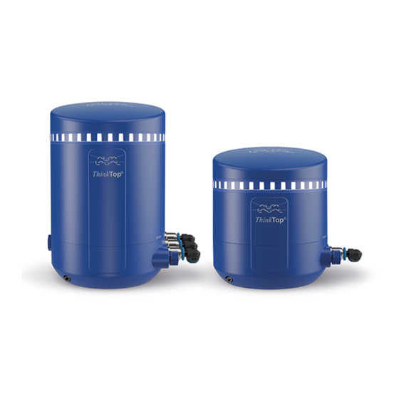
- Page 1 ThinkTop® V50 and V70 Instruction Manual Lit. Code 200000549-1-EN-GB Manual No. 100000340 www.sks-online.com www.sks-webshop.com...
- Page 2 © Alfa Laval Corporate AB 2019-05 This document and its contents is owned by Alfa Laval Corporate AB and protected by laws governing intellectual property and thereto related rights. It is the responsibility of the user of this document to comply with all applicable intellectual property laws. Without limiting any rights related to this document, no part of this document may be copied, reproduced or transmitted in any form or by any means (electronic, mechanical, photocopying, recording, or otherwise), or for any purpose, without the expressed permission or authorized by Alfa Laval Corporate AB.
-
Page 3: Table Of Contents
Contents 1 EC Declaration of Conformity ................5 2 About ThinkTop ......................7 About this manual......................7 3 Installation ........................9 Mechanical installation.................... 10 Pneumatic installation....................11 Electrical installation, Digital-IO 24V................12 Electrical installation, AS-interface................14 Electrical installation, IO-link..................15 Seat lift sensor installation..................16 4 Setup ..........................19 Auto Setup.......................19 Flex Setup....................... - Page 4 www.sks-online.com www.sks-webshop.com...
-
Page 5: Ec Declaration Of Conformity
+45 79 32 22 00 Phone No hereby declare that Top Unit for Valve Control and Indication Designation ThinkTop V50, ThinkTop V70 Type From serial number 0 to 10.000.000 is in conformity with the following directive with amendments: - EMC Directive 2014/30/EU... - Page 6 1 EC Declaration of Conformity 200000549-1-EN-GB www.sks-online.com www.sks-webshop.com...
-
Page 7: About Thinktop
2 About ThinkTop ThinkTop is a valve-top control unit that provides surveillance and control of valves during the fluid handling process. The control unit has been developed with user friendliness and robustness in mind. ThinkTop comes with a valve control sensor board for connection to any PLC system. There are three types of communication interfaces available: Digital I/O 24 VDC, AS-Interface v3.0, AS-I v2.11 and IO-link. - Page 8 2 About ThinkTop 200000549-1-EN-GB www.sks-online.com www.sks-webshop.com...
-
Page 9: Installation
3 Installation This chapter covers the installation of any ThinkTop variant within the V50 and V70 families on any Alfa Laval rising stem valve. Tools To carry out the installation, you need the following tools: Hex key Adjustable spanner or flat wrenches... -
Page 10: Mechanical Installation
3 Installation 3.1 Mechanical installation Mechanical installation is a two-step process, where you mount the sensor target to the actuator stem and the ThinkTop to the actuator top. Fit the yellow sensor target to the actuator stem. Tighten the sensor target by hand or by using a 2.5 mm hex key (1...2 Nm) 2066-0038 Mount the ThinkTop centred and flat against... -
Page 11: Pneumatic Installation
Installation 3 3.2 Pneumatic installation Before you begin the pneumatic installation, cut the hoses to the preferred length. Connect the air hoses between the air connectors on the ThinkTop and the air ports on the valve. For double seat valves, ensure that the hoses run parallel to each other and do not overlap. -
Page 12: Electrical Installation, Digital-Io 24V
3 Installation 3.3 Electrical installation, Digital-IO 24V a) Remove the top cover by turning it counter clockwise and then lifting it upwards. b) Connect the cable to the ThinkTop, and then connect the wires to the terminals according to the wiring diagram. c) Tighten the cable gland using a 19 mm wrench (3 Nm). - Page 13 Installation 3 Terminals V70 Digital-IO 24V Power supply (brown) Power supply (blue) Status OK (white) Valve de-energised (DE-EN) (black) Main valve energised (EN) (grey) Upper seat lift energised (USL) (pink) Lower seat push energised (LSP) Solenoid valve 1 for main valve (SV1) Solenoid valve 2 for USL (SV2) Solenoid valve 3 for LSP (SV3) Seat lift sensor...
-
Page 14: Electrical Installation, As-Interface
3 Installation 3.4 Electrical installation, AS-interface a) Remove the top cover by turning it counter clockwise and then lifting it upwards. b) To allocate an address, use your preferred addressing device. See the device manual for more information. c) Connect the cable to the ThinkTop, and then connect the wires to the terminals according to the wiring diagram. -
Page 15: Electrical Installation, Io-Link
Installation 3 3.5 Electrical installation, IO-link a) Remove the top cover by turning it counter clockwise and then lifting it upwards. b) Fit the cable to the M12 connector and tighten it using a 14 mm wrench (0.6...1.5 Nm). c) Put the top cover back in place. d) Turn on the power supply. -
Page 16: Seat Lift Sensor Installation
3 Installation 3.6 Seat lift sensor installation This section is relevant for V70 variants where feedback for the upper seat lift function in a double seat valve application is required. The parts referred to in this section are available as a seat lift sensor kit. - Page 17 Installation 3 Position the valve so that the mechanical target is in front of the sensor by manually controlling solenoid valve two. Fit a nut approximately half way into the thread on the sensor. Fit the sensor in the bushing, so the tip of the sensor is approximately 1 mm from the mechanical target of the valve.
- Page 18 3 Installation 200000549-1-EN-GB www.sks-online.com www.sks-webshop.com...
-
Page 19: Setup
4 Setup When the ThinkTop has been installed correctly and is powered up for the first time, it flashes green. You can then begin the setup process. Auto Setup works well for most applications, and we therefore recommend that you run Auto Setup before trying any of the other setup options. -
Page 20: Flex Setup
4 Setup 4.2 Flex Setup Flex Setup allows the setup of any rising stem valve and is a flexible alternative to Auto Setup. However, Flex Setup is not able to check for common installation mistakes. Flex Setup facilitates the detection and linking of valve functions and the related positions or sensor states to the outputs. Because it relies on additional operator input, the operator must be familiar with the content of the user manual. - Page 21 Setup 4 Perform Flex Setup Remove the top cover by turning it counter clockwise and then lifting it upwards. Press the SELECT button two or three times to navigate to either the Seat valve option or the Rotary valve option, then press ENTER. Store the valve positions.
-
Page 22: Live Setup
4 Setup 4.3 Live Setup Live Setup is especially suited for live commissioning and live replacement. Unlike Auto Setup, Live Setup does not automatically activate the solenoid valves. It waits for all the detected solenoid valves to be energized by the PLC, and then saves the related positions detected by the sensor system. The light guide lights steady green when setup is completed. -
Page 23: Options
Setup 4 4.4 Options The operational functionality of the ThinkTop can be further customized with the following options. Burst clean If you want to enable the burst clean feature to optimize the cleaning process in a double seat valve application. You can enable this option both before or after setup. - Page 24 4 Setup 200000549-1-EN-GB www.sks-online.com www.sks-webshop.com...
-
Page 25: Troubleshooting
5 Troubleshooting The following table provides troubleshooting advice to resolve common issues that you might face when working with the ThinkTop. 5.1 Calculating the error code You need the error code to use the troubleshooting table. To determine the error code, you add the numbers to the right of the active LED’s. -
Page 26: Error Descriptions
5 Troubleshooting 5.2 Error descriptions Error description Troubleshooting advice The SELECT button is locked 15 Key lock active It can be unlocked by holding the ENTER button for 7s until the 4 first LEDs has come ON . 16 Sensor target missing Verify that the sensor target is installed correctly. - Page 27 Troubleshooting 5 Error description Troubleshooting advice Solenoid valve 1 is not detected. 23 Solenoid valve 1 missing - Check the solenoid valve wiring. - Rerun setup if the solenoid valve has been intentionally removed. Solenoid valve 2 is not detected 24 Solenoid valve 2 missing - Check the solenoid valve wiring.
-
Page 28: Interpreting The Error Code Patterns
5 Troubleshooting 5.3 Interpreting the error code patterns You can identify an error code by looking at the LED colour pattern. The pattern is displayed in the following table: Auto Flex Seat valve Rotary valve Error 16 17 18 19 20 21 22 23 24 25 26 27 28 29 30 31 2066-0063 Example: Auto... -
Page 29: Tips And Tricks
Troubleshooting 5 5.4 Tips and Tricks Aligning feedbacks by rearranging solenoid valve plugs For example, if you are setting up a ThinkTop with 2 solenoid valves on a double seat valve with only the lower seat lift function installed. Due to the 2 SV ThinkTop comes with SV1 (main) and SV2 (USL) you will find that after you have done the setup that the actual lower seat position of the valve is keyed to the feedback labelled USL and the related blue colour.
Need help?
Do you have a question about the ThinkTop V70 and is the answer not in the manual?
Questions and answers