
Related Manuals for Alfa Laval EPC-400


Summary of Contents for Alfa Laval EPC-400
- Page 1 Component Description EPC-400 Control Unit Product No. 31830-6149-1 31830-6149-2 31830-6149-3 31830-6228-1 31830-6228-2 31830-6228-3 Printed Nov 1998 Book No. 1818053-02 V3 Alfa Laval Marine & Power...
- Page 2 Alfa Laval reserve the right to make changes at any time without prior notice. Any comments regarding possible errors and omissions or suggestions for improvement of this publication would be gratefully appreciated. Copies of this publication can be ordered from your local Alfa Laval company.
-
Page 3: Table Of Contents
Contents Overview Location of Cable Entries Terminal Protectors Function Description Spare Parts Application Working Principle Design 2.3.1 Front Panel 2.3.2 Label Inside the Front Panel 2.3.3 Control Module 2.3.4 Power Supply Operation Process Operation Parameter Setting 3.2.1 Overview 3.2.2 Setting Procedure Maintenance Preventive Maintenance 4.1.1... - Page 4 1818053-02...
-
Page 5: Overview
Overview EPC-400 control unit is used within a separation system for automatic control of the separation process. The unit is microprocessor based and comprises output functions for control of ancillary equipment and input functions for monitoring and alarm. The EPC-400 is programmable to suit different separator systems and different operation conditions. - Page 6 1 Overview EPC-400 1818053-02...
-
Page 7: Function Description
Function Description 2.1 Application The EPC-400 control unit is used in ALCAP separation systems. 2.2 Working Principle The EPC-400 is used for monitoring and control of the separation process. It controls starting, separation, sludge discharge and stopping sequences. The process is monitored via input signals from sensors, etc., and an alarm is given if... -
Page 8: Design
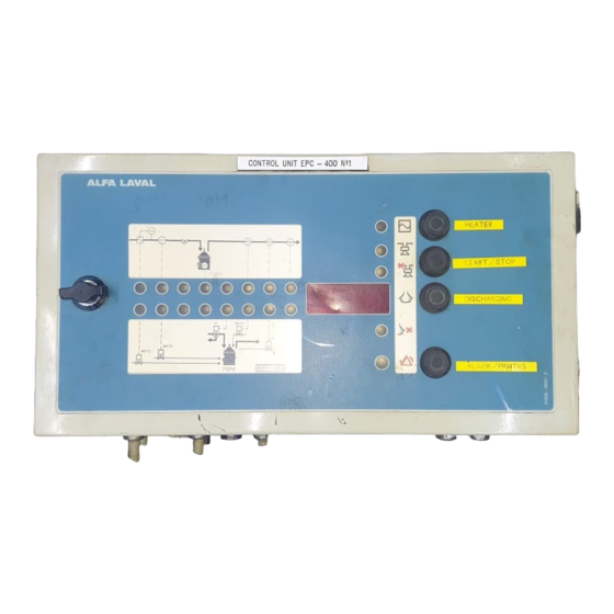
2 Function Description EPC-400 2.3 Design 2.3.1 Front Panel The front panel of the EPC-400 control unit provides a display and LEDs (light emitting diodes) for alarm and process information, and push-buttons for on/off and manual process control. Four push-buttons are located to the right on the panel. -
Page 9: Label Inside The Front Panel
EPC-400 2 Function Description An on/off switch combined with a fuse is located behind the front panel. The power is intended to be permanently on. When work is to be carried out in the control unit the mains supply should be externally switched off. -
Page 10: Power Supply
2 Function Description EPC-400 It also contains built-in relays, which are used e.g. for the output signals to ancillary components, stop signal to the separator motor starter and control signals to an optional heater. The rear circuit board (2b) monitors the water... -
Page 11: Operation
Operation 3.1 Process Operation The process operation is described in the “Operating Instructions” manual. 3.2 Parameter Setting The parameter setting is performed initially at installation, and also when required during operation. How to set parameters is described below, while the meaning and values of the parameters are described separately in the Parameter List for each system. -
Page 12: Overview
3 Operation EPC-400 3.2.1 Overview The principle of parameter setting is: 1. Set the mode selector in position P (programming). 2. Select parameter number or code with the two upper push buttons (“1” for increasing and “2”for decreasing the number). The number or code is shown in the left part of the display (7). - Page 13 EPC-400 3 Operation Installation Parameters 4. Press the same button again and keep it pressed until code C2 2 appears. This indicates installation parameters. 5. Change the code to C2 12 using the parameter value push button. This makes it possible to change the values of the installation parameters.
- Page 14 3 Operation EPC-400 10. Set the process parameters in the same way as the installation parameters, see points 6 and 7. End of Parameter Setting 11. When all parameters are appropriately adjusted, switch the mode selector to L (local). 12. Close the front panel.
-
Page 15: Maintenance
Maintenance The EPC-400 has a test program for self testing and separation system testing. For more information, see the “Alarms and Fault Finding” manual. 4.1 Preventive Maintenance It is recommended to carry out a lamp (LED) test once a month. No other regular maintenance is required. -
Page 16: Corrective Maintenance
Alarm 10 V AC supply to the board A1-4 20 V AC supply to the board A1-4 At restart with new fuse, switch power ON-OFF-ON Power terminal Fuse Functions influenced Alarm F12, F13 Power to the EPC-400 Display black 1818053-02... -
Page 17: Replacement Of Control Module
Control Module If a persistent fault is found in the control module it must not be repaired, but must be replaced and sent to an Alfa Laval representative for repair. 1. Make a note of all the actual parameter settings. - Page 18 4 Maintenance EPC-400 6. Pull out the wire terminal sockets by hand on the rear circuit board. 7. Lift off the control module from the cabinet and replace it with a spare module. 8. Fit the spare module in reverse order.
-
Page 19: Technical Data
Technical Data 5.1 Specification Mains voltage 48 V AC +10 % –15 % Total power requirement During separation: max. 110 VA During sludge discharge: max. 200 VA Power requirement for outputs Inrush: max. 5 x 45 VA Continuous: max. 5 x 23 VA 50/60 Hz ±5% Frequency Max. -
Page 20: Dimensions
5 Technical Data EPC-400 Max. 55 °C Ambient temperature Degree of protection IP 65 Ref. 1762575 Rev.11 5.2 Dimensions Ref. 1762575 Rev.11 Article No. Type Separator type 31830-6149-1 EPC-400 FOPX 31830-6228-1 31830-6149-2 EPC-400 LOPX 31830-6228-2 31830-6149-3 EPC-400 MFPX 31830-6228-3 1818053-02... -
Page 21: Circuit Diagram
EPC-400 5 Technical Data 5.3 Circuit Diagram Ref. 31830-3982-0 Rev. 6 1818053-02... - Page 22 5 Technical Data EPC-400 1818053-02...
-
Page 23: Installation
NOTE If the specifications are not followed, Alfa Laval cannot be held responsible for any malfunction of the installation. 6.1 Mounting Recommendation The EPC is wall-mounted by means of two keyhole lugs and two fastening lugs. -
Page 24: Cable Routing
6 Installation EPC-400 6.2 Cable Routing Recommendation Correct routing inside the EPC cabinet: • Keep cables short inside the cabinet. • Keep signal and power cables separate. 6.3 Location of Cable Entries Specification To prevent the reception of electrical noise inside the cabinet it is essential that all cables are routed correctly. -
Page 25: Terminal Protectors
EPC-400 6 Installation 6.4 Terminal Protectors Specification The terminal protectors must NOT be removed until the separator system is about to be commissioned. During installation, terminal protectors shield the EPC’s circuit board against possible damage from welding currents, etc. Cables entering the cabinet can still be... - Page 26 6 Installation EPC-400 1818053-02...
-
Page 27: Spare Parts
Spare Parts Item Article No. Description Remarks 31830-5010-4 Control module 4900795-18 Transformer 21–48 V/10–20–24 V 4900860-26 Circuit breaker 3.0 A with push-push 4901008-02 Rubber push button extension 4901156-03 Screw terminal 31830-5021-2 Spare parts kit, including: 1) 2) 4900850-21 Fuse, slow acting 2.5 A, 5x20 4900850-14 Fuse, slow acting... - Page 28 7 Spare Parts EPC-400 1818053-02...
Need help?
Do you have a question about the EPC-400 and is the answer not in the manual?
Questions and answers
Здравствуйте. Блок EPC-41 при запуске, ошибка А2-7, интересует что проверятся в это время. По инструкции, Calibration error. Калибровка чего? Все тесты проходят без ошибок.
When encountering an A2-7 error during startup on an Alfa Laval EPC-400, which is related to calibration, you should check the fuse F2 on the rear board (A2). This fuse supplies 10 V AC to the board, and its failure can affect functions including those connected to A1-4, which may impact calibration processes. If the fuse is replaced, restart the unit by switching the power OFF and then ON again.
This answer is automatically generated
Good day I hope you really good. I have problem on my alfa Laval DO purifier controlled by EPC400 Module. The problem is that when I start it, if it reach the sequence of disludging it make alarm and stop. I already checked All the seals and water they are good working but the problem still coming. Thanks you very much
The alarm and shutdown of the Alfa Laval DO purifier controlled by the EPC-400 module during the disludging sequence could be caused by several factors:
1. Sensor Input Exceeding Preset Values – The EPC-400 monitors the process via sensors, and if any preset limits are exceeded, an alarm is triggered.
2. Water Seal Loss – If oil is still exiting the oil outlet, the water seal may not have been lost. However, improper displacement or conditioning water levels could trigger an alarm.
3. Incorrect Parameter Settings – If process parameters such as temperature limits or times are incorrectly set, the unit may shut down.
4. Control Unit Fault – A fault in the control module could lead to unexpected shutdowns, requiring replacement.
5. Improper Sequence Execution – The module ensures proper opening and closing of water valves during discharge. Any failure in these operations may cause an alarm and shutdown.
To resolve the issue, check sensor readings, verify parameter settings, inspect water levels, and ensure proper execution of the disludging sequence.
This answer is automatically generated