
Related Manuals for Alfa Laval 762-227


Summary of Contents for Alfa Laval 762-227
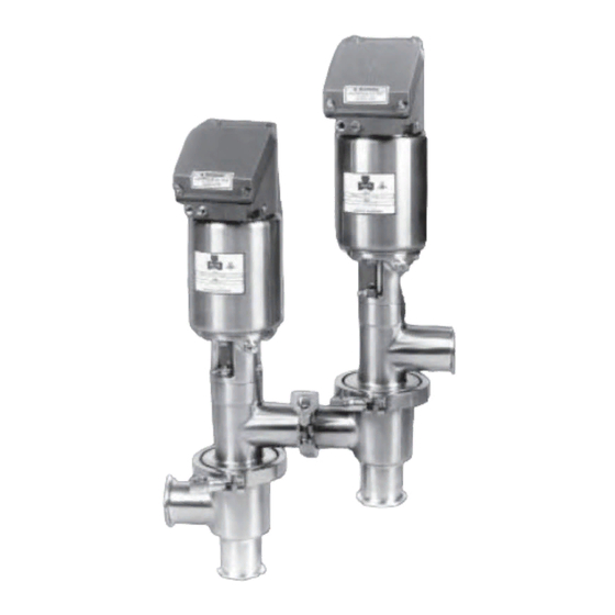
- Page 1 Instruction Manual Tri-Clover ® Flo-Diversion Valve and Panel Models 762-227, 762-227MRAL & 862W-227 Effective 8/1/03...
-
Page 2: Table Of Contents
This manual contains installation, operation, and repair instructions, with parts lists, for the Model 762- 227, 762-227 MRAL and 862W-227 Flo-Diversion Valves and control panels designed and manufactured by Alfa Laval Inc.. It also provides a trouble shooting chart to assist in determining electrical and mechanical malfunctions, if they should occur. -
Page 3: Safety
IMPORTANT SAFETY INFORMATION Safety is very important! DO NOT attempt to modify any Alfa Laval product. To do so could create unsafe conditions and void all warranties. DO NOT place any Alfa Laval product in an application where general product service ratings are exceeded. -
Page 4: Introduction
The purpose of the 762-227 MRAL Reverse Acting Flo-Diversion Valve is to eliminate hydraulic shock in systems where the differential pressure across the valve is 30 psig or greater. The design of the valve allows closing against the process flow rather than with the flow as conventional valves do. - Page 5 INTRODUCTION The control panel contains a three position selector switch for operating the valve in product flow, cleaning, or inspection positions. A manual diversion push button allows the operator to divert product flow into the balance tank at any time during operation of the equipment. Inside the control panel are solenoid valves, timers and relays required for control of the valves.
- Page 6 INTRODUCTION The product is circulated through the regenerator and heater, and into the holding tube and Flo-Diversion Valve. The valve diverts product back to the balance tank until a safe pasteurization temperature is reached. When legal temperature is reached, the temperature limit switch closes the circuit to the solenoid valve (SVl) for the divert valve.
-
Page 7: Installation
INSTALLATION UNPACKING AND INSTALLING EQUIPMENT UNPACKING EQUIPMENT The Flo-Diversion Valve should be unpacked immediately upon receipt from the factory and carefully inspected for damage that may have occurred during shipping. The equipment should also be checked against the bill of lading to make sure there are no shortages. Any damage or shortage should be immediately reported to the carrier. - Page 8 INSTALLATION INSTALLING THE EQUIPMENT Secure the valves to an adequate support using appropriate pipe hangers, and connect the valves to the product piping. The valves are furnished with Tri-Clamp fittings for simplified connections. Make ® sure the piping is self supporting and that the joints at the valves are properly aligned to prevent strain on the valves.
-
Page 9: Prestarting
INSTALLATION PRESTARTING PRESTART TESTS Before putting the Flo-Diversion Valve into operation it is necessary to check the installation. To make sure that all parts of the system are functioning properly, the following checklist should be used. 1. Air Supply. Make sure all air line connections are tight and free of leaks. Before turning on the air supply, loosen the adjusting screw on top of the Filter-Regulator until an compression on the spring is released. - Page 10 When the switch is released, the valves will follow the normal "product" cycle. 4. MICROSWITCH TEST for 762-227 & 862W-227. The microswitches in the valves are safety devices. They are adjusted so that the timing pump will not run at sub-legal pasteurization temperatures, unless the valves are completely and properly assembled.
- Page 11 INSTALLATION H. Turn the selector switch to the “PRODUCT” position and the timing pump will not start. Remove the gap gauge and reassemble the valve. Ensure the valve is properly and completely assembled. ALTERNATE TEST METHOD CAN ALSO BE USED TO TEST THE MICROSWITCH ADJUSTMENT. Note: These are unofficial test methods for troubleshooting purposes only.
- Page 12 If the valves do not meet either of these tests, the microswitch must be adjusted. Refer to topic “Adjustments”. 5. MICROSWITCH ADJUSTMENT for 762-227 & 862W-227. The Flo-Diversion Valve is precision equipment, and has been carefully manufactured and adjusted before leaving the factory. As is the case with most precision machinery however, the adjustments may have been disturbed during shipping or installation.
- Page 13 INSTALLATION Remove the valve body clamp and the upper valve port clamp on the leak detect valve. This will allow access to the valve stem when the valve is lifted off the lower body. The divert valve requires removal of the lower body for access to the valve stem. Apply air to the actuator to move the stem off the upper seat.
- Page 14 INSTALLATION F. Unscrew the nut at the end of the exposed stem for stem removal. G. Slide the stem and o-ring off the stem connected to the actuator. H. Slide the gauge ( stored inside control housing ) onto the stem connected to the actuator. Reassemble the two stem together without the o-ring and tighten the nut to secure the gauge between the two stems.
- Page 15 INSTALLATION Divert Valve Cam This cam and its circuitry controls the divert valve opening and closing during the cleaning cycle. The switch is wired into the circuit for solenoid valve (SV1) When the switch is activated by the cam, the solenoid is energized allowing air into to the divert valve actuator.
-
Page 16: Cleaning
MAINTENANCE CLEANING The Flo-Diversion Valve is used in the food processing industry and therefore is subject to frequent cleaning. The clean-in-place (CIP) capability permits cleaning of the process passages and the components that come in contact with the product, without dismantling the valve. The entire cleaning process is accomplished automatically once the selector switch has been placed in the “clean’’... -
Page 17: Introduction
The valves, actuators and control unit should be disassembled to the extent necessary for inspection or needed repair. 762-227 & 862W-227 VALVE DISASSEMBLY 1. Be sure the timing pump is turned off. Remove the lower body line clamps on the divert valve and the upper body outlet line clamp from the leak detect valve. -
Page 18: Valve Component Inspection
MAINTENANCE 762-227MRAL VALVE DISASSEMBLY 1. Be sure the timing pump is turned off. Remove the four tri-clamps that connect the valve to the process system. To separate the Flo-Diversion Valve into two valves remove the tri-clamp that connects the valves together. 2. -
Page 19: Control Top Disassembly
MAINTENANCE CONTROL TOP DISASSEMBLY cleaning. WARNING To prevent personal injury, disconnect all electrical and pneumatic power to the control top. Hazardous voltage can cause electrical shock. The actuator stem moves with extreme force and suddenness. 1. Disconnect the Cable. Unscrew the knurled ring of the cable counter clockwise. After the threads disengage, pull the cable off of the connector. -
Page 20: Actuator Bushing / Packing Replacement
MAINTENANCE ACTUATOR BUSHING / PACKING REPLACEMENT WARNING To prevent personal injury, do not attempt to cut actuator open. The actuator spring is compressed and under load. Bushings guide the actuator stem while packings provide sealing around the stem. The bushing and packing should both be replaced if one or the other fails. Even if only one end fails both ends of the actuator should be serviced. -
Page 21: Control Top Assembly
MAINTENANCE CONTROL TOP ASSEMBLY (* STP is a registered trademark of STP Corporation.) 1. Attach the activating nut with the two retaining rings to the non-threaded end of the actuator stem. 2. Place all seals on the base. • Three o-rings on the bottom of the base. IMPORTANT: When installing the largest diameter o-ring start it in groove opposite the air relief notch and press it in towards the notch. - Page 22 MAINTENANCE 3. Place the solenoid on top of the selector block and fasten with two screws. STOP BLOCK INSTALLATION - NO SOLENOID ONLY 1. Install all four o-rings into the stop block. 2. Place S.S. stop block support on top of stop block and fasten the stop block with two screws. 3.
-
Page 23: Valve Assembly
IMPORTANT: Replace nylon lock before threading valve stem onto actuator stem, see section Actuator Stem Nylon Lock Replacement. 762-227 & 862W-227 VALVE ASSEMBLY 1. Place o-ring into counter bore above air port on yoke. 2. Place green bearing retainer into bottom of actuator. - Page 24 MAINTENANCE 762-227MRAL VALVE ASSEMBLY 1. Place o-ring into counter bore above air port on yoke. 2. Place green bearing retainer into bottom of actuator. 3. Place actuator onto yoke with short shaft end into the yoke. Align yoke air port with unthreaded thru hole in actuator end cap.
-
Page 25: Troubleshooting
TROUBLESHOOTING TROUBLESHOOTING GUIDELINES The Flo-Diversion valve is relatively maintenance free with the exception periodic inspection. As with any precision equipment, however, occasional problems can arise. The troubleshooting chart provides a means of determining and correcting most mechanical and electrical problems. Note: The troubleshooting chart is divided into two parts, one mechanical and electrical. - Page 26 TROUBLESHOOTING ELECTRICAL TROUBLE PROBLEM PROBLEM PROBLEM 1. Product a1. Put test lamp on terminals two and three. If a. Timing pump does not Position. lamp lights, proceed below. If no light, check start - cold power main and fuse in STLR controller. Blown temperature.
- Page 27 TROUBLESHOOTING ELECTRICAL TROUBLE (CONT.) PROBLEM PROBLEM PROBLEM 1. Product e. Green light not on e1. Replace bulb with known working one. Position (Cont.) (valve moved to forward (24VAC). If light not on, proceed below. flow). e2. Put test lamp on terminals 2 and 7. If light on, check 220V to 24V light transformer.
-
Page 28: Parts List
PARTS LIST CONTROL PANEL COMPONENTS • 3-position selector switch Places divert and leak detect valve in proper circuit. "Inspect" puts air on valves to permit dismantling. Uses solenoid valve #1 and solenoid valve #2. "Product" permits valve function only in approved and recognized procedures. Uses solenoid valve #1, solenoid valve #2, microswitch #1, microswitch #2, timer #2, and timer #3. -
Page 29: Panel
PARTS LIST PANEL How to order replacement parts All orders for repair parts must contain the following data: 1. Complete model number (from name plate). 2. Serial number (from name plate). 3. Key number and description. The following exploded view and accompanying parts facilitate ordering repair parts from the factory. -
Page 30: 74-115-X-Y Control Housing
74-115-X-Y CONTROL HOUSING CONTROL HOUSING CONTROL HOUSING WITHOUT SOLENOID WITH SOLENOID 54-98 Blocked Hole In 9613600270 Note Selector 17-344-U Selector Block STOP BLOCK SUPPORT T304 Block Location O-Ring (Air Passage To 3 Req. 54-99 Actuator Located 34-1114-316 Stop Block Here) Air Passage Air Tube SC505R-SS... - Page 31 14-125-S Thumb Screw 17-337B-E Gasket (4 Req.) 17-340B-E Gasket 17-139-U-90 O-Ring (4 Req.) 1-36 Base SC107R-SS Screw 44-251B 1-37 Back Cover Base Cover EL-97515-0058 SC1307E-SS Cable Assembly Screw (3 Req.) 17-348 Pressure Relief SC1307H-SS Screw LWA1300-SS Lockwasher 25-425-04 17-109-U Nylon Retainer O-Ring EL-97750-0049 Wire Harness...
-
Page 32: 762-227M
PARTS LIST 762-227M How to order replacement parts All orders for repair parts must contain the following data: Note: Part numbers are for reference. Consult Service Kit Catalogue or Spares CD for proper service kits. 1. Complete model number (from name plate). 2. - Page 33 762227MEXP...
-
Page 34: 862W-227
PARTS LIST 862W-227 How to order replacement parts All orders for repair parts must contain the following data: 1. Complete model number (from name plate). 2. Serial number (from name plate). 3. Key number and description. The following exploded view and accompanying parts list facilitate ordering repair parts from the factory. -
Page 36: 762-227Mral
PARTS LIST 762-227MRAL How to order replacement parts All orders for repair parts must contain the following data: 1. Complete model number (from name plate). 2. Serial number (from name plate). 3. Key number and description The following exploded view and accompanying parts list facilitate ordering repair parts from the factory. - Page 37 PARTS LIST 23 and 24 23 and 24...
-
Page 38: Allen Bradley Slc 500 Plc
ALLEN-BRADLEY SLC 500 PLC TRI-CLOVER PANEL MODELS 48-2762-1 AND 48-2762-2 The following section of the manual covers the use and application of the Tri-Clover programmable controller version of the Flo-Diversion Valve Panel. The control panel utilizes the Allen Bradley SLC 500 small programmable logic controller (PLC) with UVPROM memory chip to retain permanent logic storage for the Flo-Diversion application program. - Page 39 Refer to the picture of the Allen-Bradley SLC 500 below. NOTE: Contact Alfa Laval for information on new Micro Logix 1200 panel. A place is provided for the Inspecting Regulatory Agencies to place a seal on the panel. The panel door clamping latch has a hole in which to insert a wire seal.
- Page 40 ALLEN-BRADLEY SLC 500 PLC If a Regulatory seal has been violated, either the door seal or the memory seal, the following procedure should be accomplished before attempting to place the control panel in operation 1. Remove power from the control panel. 2.
-
Page 41: Software Version Numbers (As Of 8/4/94)
ALLEN-BRADLEY SLC 500 PLC SOFTWARE VERSION NUMBERS (AS OF 8/4/94) It is to be expected that software revisions will have to be accomplished as State and/or Federal regulations dictate. The Federal (FDA) Regulatory Agency will be notified of each Tri-Clover software revision and version number. -
Page 42: Memorey Modules
ALLEN-BRADLEY SLC 500 PLC FIXED HARDWARE STYLE The SLC 500 Fixed Hardware Style controllers consist of a CPU with 1000 instruction capacity, a power supply and a fixed number of I/O contained in a single package. These processors are designed for industrial environments with ambient temperature from 0 to +60C. -
Page 43: Input And Output Status Indicators
ALLEN-BRADLEY SLC 500 PLC INPUT AND OUTPUT STATUS INDICATORS Red LED indicators are identified with address numbers that correspond to the numbers on the inside of the hinged covers for easy verification. The 18 Inputs are 0-17, wired to the bottom of the controller. - Page 44 ALLEN-BRADLEY SLC 500 PLC Output # Name & Function Timing Pump (or Homogenizer used as Timing Pump) – Output enables pump start/stop circuit. Output is interlocked to valve microswitches during sub-legal temperatures to prevent forwarding of unsafe product. Output is disabled during CIP operations. Homogenizer (when not used as timing pump) –...
-
Page 45: Flo-Diversion Panel #48-2762-1 Without Solenoids
ALLEN-BRADLEY SLC 500 PLC FLO-DIVERSION PANEL #48-2762-1 WITHOUT SOLENOIDS 14" 18" RED LT GREEN LT DIVERT FORWARD PROD MANUAL DIVERT SEAL WIRE THROUGH HOLES IN LATCH & DOOR LIP Tri-Clover Inc. Kenosha, Wisconsin PANEL NO. DRAWING NO. 48-2762-1 91-1310 SERIAL NO. SOFTWARE VER. - Page 46 ALLEN-BRADLEY SLC 500 PLC ALLEN BRADLEY SLC 500 PLC PROCESOR OUTPUT MEMORY PLEXIGLASS UV PROM CHIP WINDOW INUT PLUG-IN-RELAY 24 VAC COIL TRANSFORMER TERMINALS 115 VAC (29) 24 VAC (8) 8" MICROSWITCH WIRING CONNECTIONS 14"...
-
Page 47: Wiring Diagram For Flo-Diversion Panel #48-2762-1
ALLEN-BRADLEY SLC 500 PLC WIRING DIAGRAM FOR FLO-DIVERSION PANEL #48-2762-1... - Page 48 ALLEN-BRADLEY SLC 500 PLC SLC-500 OUTPUT START VDC 1 M-TP O.L. STOP TIMING PUMP OR HOMO MOTOR OUT 0 USED AS TIMING M-TP PUMP O.L. START STOP HOMO (WHEN M-HOMO NOT USED AS OUT 1 TIMING PUMP) M-HOMO START O.L. STOP M-CP CLEANING PUMP...
-
Page 49: External Wiring Diagram For Flo-Diversion Panel 48-2762-1
ALLEN-BRADLEY SLC 500 PLC EXTERNAL WIRING DIAGRAM FOR FLO-DIVERSION PANEL 48-2762-1 REQUIRED WIRING LOW VOLTAGEE BLUE TERMINALS TERMINAL BLOCK IN FLO-DIVERSION PANEL 120 VAC 60 HZ FUSE "TEST" PUSHBUTTON CHART DRIVE DIVERSION SWITCH PRESSURE SWITCH TERMINAL CONNECTIONS: TAYLOR AND ANDERSON CONTROLLERS FREQUENCY PEN HTST CONTROLLER (STLR) - Page 50 ALLEN-BRADLEY SLC 500 PLC OPTIONAL WIRING (PLUS REQUIRED WIRING) LOW VOLTAGE BLUE TERMINAL TERMINAL BLOCK IN FLO-DIVERSION PANEL 9-PLC INPUT TO PULSE DIVERT VALVE DURING CIP 120 VAC 10-PLC INPUT TO PULSE LEAK DETECT VALVE DURING CIP INPUTS 11-PLC INPUT TO RUN BOOSTER PUMP DURING CIP 26-PLC OUTPUT TO SIGNAL "FORWARD FLOW"...
- Page 51 ALLEN-BRADLEY SLC 500 PLC FLO-DIVERSION PANEL #48-2762-2 WITH SOLENOIDS 14" 18" RED LT GREEN LT DIVERT FORWARD PROD MANUAL DIVERT FILTER SEAL WIRE THROUGH HOLES IN LATCH & DOOR LIP Tri-Clover Inc. Kenosha, Wisconsin PANEL NO. DRAWING NO. 48-2762-2 91-1307 SERIAL NO.
- Page 52 ALLEN-BRADLEY SLC 500 PLC ALLEN BRADLEY SLC 500 PLC PROCESSOR OUTPUT MEMORY PLEXIGLASS UV PROM CHIP WINDOW COMMUNICATIONS CONNECTOR INPUT 22 21 PLUG-IN-RELAY 24 VAC COIL SOLENOIDS TRANSFORMER 120 VAC COILS TERMINALS 115 VAC (29) 24 VAC (8) 8" MICROSWITCH VALVE AIR WIRING CONNECTIONS LINE CONNECTIONS...
-
Page 53: Wiring Diagram For Flo-Diversion Panel #48-2762-2
ALLEN-BRADLEY SLC 500 PLC WIRING DIAGRAM FOR FLO-DIVERSION PANEL #48-2762-2 ALLEN BRADLEY SLC-500 I/O DRAWING 120 VOLT AC 60 HZ (F FOR STLR INSTRUMENT) SLC-500 INPUT NEUT. GND. A.C. COM. PRODUCT INSPECT CLEAN PRODUCT IN 0 INSPECT IN 1 CLEAN IN 2 MANUAL DIVERSION... - Page 54 ALLEN-BRADLEY SLC 500 PLC SLC-500 OUTPUT VDC 1 TIMING PUMP START O.L. STOP M-TP OR HOMO MOTOR OUT 0 USED AS TIMING PUMP M-TP START O.L. STOP M-HOMO HOMO (WHEN OUT 1 NOT USED AS TIMING PUMP) M-HOMO START O.L. STOP M-CP OUT 2...
- Page 55 ALLEN-BRADLEY SLC 500 PLC EXTERNAL WIRING DIAGRAM FOR FLO-DIVERSION PANEL #48-2762-2 REQUIRED WIRING LOW VOLTAGEE BLUE TERMINALS TERMINAL BLOCK IN FLO-DIVERSION PANEL 120 VAC 60 HZ FUSE "TEST" PUSHBUTTON CHART DRIVE PRESSURE SWITCH DIVERSION SWITCH TERMINAL CONNECTIONS: TAYLOR AND ANDERSON CONTROLLERS FREQUENCY PEN HTST CONTROLLER (STLR)
- Page 56 ALLEN-BRADLEY SLC 500 PLC...
- Page 57 ALLEN-BRADLEY SLC 500 PLC...
- Page 58 Alfa Laval Inc. 9560 58th Place, Suite 300 Kenosha, WI 53144 Phone: +1 800 558 4060 Fax: +1 800 781 2777 E-mail: usa-ese.techsupport@alfalaval.com Visit our web site at www.alfalaval.us...
Need help?
Do you have a question about the 762-227 and is the answer not in the manual?
Questions and answers