Table of Contents
Advertisement
Advertisement
Table of Contents

Subscribe to Our Youtube Channel
Related Manuals for Alfa Laval ThinkTop Digital 8


Summary of Contents for Alfa Laval ThinkTop Digital 8
- Page 1 Instruction Manual ® Digital 8 - 30 VDC PNP/NPN ThinkTop IM70824-GB6 2002-12...
- Page 2 Declaration of Conformity The designating company Alfa Laval Company Name Albuen 31, DK-6000 Kolding, Denmark Address +45 79 32 22 00 Phone No. hereby declare that ® ThinkTop p p p p Digital VDC Top Unit for Valve Control & Indication...
-
Page 4: Table Of Contents
Table of contents The information contained herein is correct at the time of issue but may be subject to change without prior notice. 1. Safety ....................6 1.1 Important information ............... 6 1.2 Warning signs .................. 6 1.3 Safety precautions................6 2. -
Page 5: Safety
1.1 Important information 1. Safety 1.2 Warning signs 1.3 Safety precautions Unsafe practices and other important information are emphasized in this manual. Warnings are emphasized by means of special signs. All warnings in the manual are summarized on this page. Pay special attention to the instructions below so that severe personal injury or damage to the top unit are avoided. -
Page 6: General Information
The ThinkT T T T T op ® is designed to ensure optimum valve control in conjunction with Alfa Laval valves and it is compatible with most PLC systems (Programmable Logic Controllers maker with PNP/NPN interface). The ThinkT T T T T op ®... -
Page 7: Technical Specifications
External seat-lift (PNP) Solenoid signals External connections Internal connections Supply sensors Solenoid common Type: Alfa Laval “No Touch” System For wire connections: See section 4.4 “Electrical connection, internal”. Features Tolerance programmes. Self adjustment programme (SRC/ARC valves only). Built-in maintenance monitor. - Page 8 ® 3. Technical specifications 3.1 ThinkTop , PLC 8-30 VDC interface Self Adjustment (SRC/ARC valves only) ® The self adjustment feature is an exceptional aspect of the ThinkTop design. A programme can be activated to allow an adjustment of the tolerance band if the seals in the valve are being compressed or are worn. When the tolerance band of the unit has been adjusted 0.3 mm, an alert warning will appear in the form of a status signal and a flashing maintenance LED.
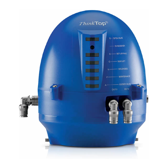
- Page 9 ® 3.1 ThinkTop , PLC 8-30 VDC interface 3. Technical specifications ® ThinkTop Visual Indications LED Indications LED B "Open valve" (Yellow) IR-Receiver LED D "Setup/Internal fault" (Red) LED C "Seat-lift 1/2" (Yellow) LED E "Solenoid valves" (Green) LED F "Maintenance"...
- Page 10 3. Technical specifications 3.1 ThinkTop ® , PLC 8-30 VDC interface Technical specifications Up to 3 solenoid valves in each unit. Type 3/2 or 5/2 valve (only possible with one 5/2 valve). Air supply 300-900 kPa (3-9 bar). Filtered air, max. particles or dirt 0.01 mm.
-
Page 11: Installation
4.1 Installation on air actuators 4. Installation Step 1 Always read the technical specifications thoroughly (see chapter 3). Always have the ThinkTop ® electrically connected by authorized personnel. ® Always install the ThinkTop before valve or relay is in a safe position. Step 2 1. - Page 12 4. Installation 4.1 Installation on air actuators Step 5 ® Fit the ø6 mm (1/4") air tubes to ThinkT T T T T op (see drawing "Air connections" later in this chapter). Step 6 Fit the air tubes to the actuator (see drawing "Air connections" later in this chapter).
- Page 13 4.1 Installation on air actuators 4. Installation Step 9 Make sure the cable gland is completely tightened. Step 10 Set up the ThinkTop ® (see chapter 5). NOTE! The unit can be set up with the cover installed by using the IR keypad. To energize the valve, use a separate air tube or be in radio contact with the control room.
-
Page 14: Installation On Series 700 Valves
4. Installation 4.2 Installation on Series 700 valves Step 1 Installation on air 1. Remove the cover by loosening the three cross recess actuators: screws. 2. Separate the adapter from the base by loosening the three recess screws on top of the base. Step 2 1. -
Page 15: Air Connections
4.3 Air connections 4. Installation Air restriction (throttle function) air inlet/outlet Air out 1A Air exhaust Manual hold override Air out 1B (5/2 port solenoid valve only) Solenoid valve Air out 2 Air out 3 Air in... -
Page 16: Electrical Connection, Internal
4. Installation 4.4 Electrical connection, internal 4.5 Example of connecting power supplies Closed valve Solenoid 1 Open valve Solenoid 2 Feedback signals to Seat-lift 1 digital interface Solenoid 3 Seat-lift 2 Digitale interface Supply + command signals Status Supply - NPN/PNP Jumper Jumper Solenoid common... -
Page 17: Setup Diagram
If no button is pressed during the time-out time, go to normal condition (cancel & exit). 6. SRC/ARC valves: Self-adjust (step 7) must be activated. If you choose NOT to use the self-adjustment programme, Alfa Laval recommends to use the valve type 4 (step 2), instead of type 1 (bigger tolerances). - Page 18 ® 5. Setup diagram 5.1 ThinkTop setup utilising IR keypad LED D, A steady LED D, A steady LED D, A steady LED D, A steady LED D, A steady if closed position enabled LED D steady LED D steady LED D steady LED D steady LED D steady, A flashing...
-
Page 19: Thinktop Setup Utilising Local 'I' And 'Ii' Keys
If no button is pressed during the time-out time, go to normal condition (cancel & exit). 6. SRC/ARC valves: Self-adjust (step 7) must be activated. If you choose NOT to use the self-adjustment programme, Alfa Laval recommends to use the valve type 4 (step 2), instead of type 1 (bigger tolerances). - Page 20 5. Setup diagram 5.2 ThinkTop ® setup utilising local ‘I’ and’II’ keys LED D, A steady LED D, A steady LED D, A steady LED D, A steady LED D, A steady if closed position enabled LED D steady LED D steady LED D steady LED D steady LED D steady, A flashing...
-
Page 21: Fault Finding
6.1 Fault finding and LEDs 6. Fault finding ® Below is stated the meaning of the LEDs' indications for fault finding in connection with the operation of the ThinkTop Red flashing: Unit in set-up mode or internal software fault. If internal software fault, re-programme unit. Red steady: Unit in set-up mode or internal hardware fault. - Page 22 6. Fault finding 6.1 Fault finding and LEDs Yellow steady: Position A (closed valve). Yellow A Yellow steady: Position B (open valve). Yellow B Yellow steady: Position C (Seat lift 1-2 or external sensors). Yellow C Green steady: Solenoid valves activated. Green E Note! During set-up LED lights have different functions.
-
Page 23: Maintenance
7.1 Dismantling of ThinkTop ® 7. Maintenance Study the instructions carefully. Handle scrap correctly. Always keep spare X-rings in stock. Step 1 1. Remove the ThinkTop ® from the actuator. 2. Pull out X-ring and replace it. Step 2 1. Untighten the three screws. ®... - Page 24 ® 7. Maintenance 7.1 Dismantling of ThinkTop Study the instructions carefully. Handle scrap correctly. Always keep spare X-rings in stock. Step 5 To remove the sensor unit untighten screw and pull out the sensor unit.
-
Page 25: Assembly Of Thinktop
® 7.2 Assembly of ThinkTop 7. Maintenance Study the instructions carefully. Handle scrap correctly. Always keep spare X-rings in stock. Step 1 Place sensor unit in base and tighten screw (torque: 1 Nm). Step 2 Assemble base with adapter by turning adapter slightly anticlockwise and tighten the three screws (1.9 Nm). - Page 26 7. Maintenance 7.2 Assembly of ThinkTop ® Study the instructions carefully. Handle scrap correctly. Always keep spare X-rings in stock. Step 5 1. Replace X-ring. 2. Mount ThinkTop ® on actuator.
-
Page 27: Dismantling And Assembly Of Series 700 Valves
7.3 Dismantling and assembly of Series 700 Valves 7. Maintenance Study the instructions carefully. Handle scrap correctly. Always keep spare X-rings in stock. Step 1 Installation on air 1. Remove the cover by loosening the three cross recess actuators: screws. 2. -
Page 29: Parts List
® 8.1 ThinkTop Digital 8-30 VDC PNP/NPN 8. Parts list The drawing and the parts list include all items. Parts List Spare Parts Pos. Denomination Denomination Item number Shell Sensor unit Digital 8-30 VDC PNP/NPN ..9612-5627-01 Shell O-ring, NBR Solenoid valve 3/2, 24 VDC ...... - Page 30 ® 8. Parts list 8.1 ThinkTop Digital 8-30 VDC PNP/NPN This page shows an exploded drawing of the ThinkTop ® The drawing includes all items of the top unit. Exploded Drawing...
-
Page 31: Thinktop ® Series 700 Valves
® 8.2 ThinkTop Series 700 valves 8. Parts list The drawing and the parts list include all items. Parts List Spare Parts Pos. Denomination Denomination 1/4” Air connec. Shell Sensor unit Digital 8-30 VDC PNP/NPN ..9612-5627-01 Screw Washer Solenoid valve 3/2, 24 VDC ...... 9611-99-3324 Sensor unit Solenoid valve 5/2, 24 VDC ...... - Page 32 ® 8. Parts list 8.2 ThinkTop Series 700 valves This page shows an exploded drawing of the ThinkTop ® The drawing includes all items of the top unit. Exploded Drawing...
- Page 33 How to contact Alfa Laval Contact details for all countries are continually updated on our website. Please visit www.alfalaval.com to access the information direct.
Need help?
Do you have a question about the ThinkTop Digital 8 and is the answer not in the manual?
Questions and answers