Table of Contents
Advertisement
Quick Links
TM
T
S
RI
TAR MPPT 600V
Solar Charging System Controller
Installation, Operation and Maintenance Manu al
For the most recent manual revisions, see the version
at: www.morningstarcorp.com
Solar Battery Charger with
TrakStar
Maximum Power Point Tracking Technology
TM
www.morningstarcorp.com
MODELS
TS-MPPT-60-600V-48
TS-MPPT-60-600V-48-DB
MAXIMUM POWER POINT TRACKING
Advertisement
Table of Contents

Related Manuals for Morningstar TRISTAR TS-MPPT-60-600V-48-DB


Summary of Contents for Morningstar TRISTAR TS-MPPT-60-600V-48-DB
- Page 1 TAR MPPT 600V Solar Charging System Controller Installation, Operation and Maintenance Manu al For the most recent manual revisions, see the version at: www.morningstarcorp.com Solar Battery Charger with TrakStar Maximum Power Point Tracking Technology www.morningstarcorp.com MODELS TS-MPPT-60-600V-48 TS-MPPT-60-600V-48-DB MAXIMUM POWER POINT TRACKING...
-
Page 2: Table Of Contents
4.4 LED Indications 4.5 Protections, Faults & Alarms 5.0 Networking and Communications 5.1 Introduction 5.2 Morningstar MeterBus 5.3 Serial RS-232 ... -
Page 3: Important Safety Instructions
Table of Contents (Cont.) 1.0 Important Safety Instructions SAVE THESE INSTRUCTIONS. 6.0 Troubleshooting This manual contains important safety, installation and operating instructions for the 6.1 Battery Charging and Performance Issues TriStar MPPT 600V solar controller. The following symbols are used throughout this manual to indicate potentially dangerous conditions or mark important safety instructions: 6.2 Network and Communications Issues Maintenance and Service... - Page 4 Informations de Sécurité • is c ar e contro er is to e connecte to C circ its on ese C connections are i entifie by the symbol below: • ise to tes es instr ctions et es a ertisse ents fi rant ans e an e a ant e co - mencer l’installation.
- Page 5 • Ce contrôleur de charge ne doit être connecté qu’à des circuits en courant continu. Ces connex- • Servicing of batteries should be performed, or supervised, by personnel knowledgeable about ions CC sont i entifi es ar e s o e ci esso s batteries, and the proper safety precautions.
-
Page 6: Getting Started
Getting Started • Des gaz explosifs de batterie peuvent être présents pendant la charge. Assurez-vous qu’une venti- ation s fisante ac e es a • Ne fumez jamais dans la zone des batteries 2.1 Overview • En cas de contact de l’électrolyte avec la peau, lavez avec du savon et de l’eau. En cas de contact de l’électrolyte avec les yeux, rincez abondamment avec de l’eau fraîche et consultez un médecin. -
Page 7: Versions And Ratings
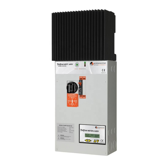
2.4 Features NOTE: This equipment has been tested and found to comply with the limits for a Class B digital device, pursuant to Part 15 of the FCC rules. These limits are designed to provide reasonable protec- The features of the TS-MPPT-60-600V-48 model are shown in Figure 2-1 below. An explanation tion against harmful interference in a residential installation. - Page 8 11 - Battery Negative Power Terminal Negative terminal for negative battery cable termination 12 - Remote Temperature Sensor Terminals Connection point for a Morningstar RTS to remotely monitor battery temperature 13 - Wiring Box Cover Sheet metal wiring box cover protects power connections...
- Page 9 Aluminum heatsink to dissipate controller heat (the TriStar MPPT 600V is 100% passively cooled for reliability) The accessories described below are available for purchase separately from your authorized 2 - Battery Negative Power Terminal Morningstar dealer. Please see the individual product manuals for installation and operation Power connection for (-) battery cable termination details.
-
Page 10: Installation
Installation Recommended Tools: • Wire strippers • Pliers • Wire cutters • Drill3/32” (2.5 mm) drill bit • #2 & #0 Phillips screwdriver • Level 3.1 General Information • slotted screwdrivers • hack saw (cutting conduit) WARNING: Equipment Damage or Risk of Explosion Never install the TriStar MPPT 600V in an enclosure with vented/flooded batteries. -
Page 11: Conduit Knock-Outs And Wiring Routing
3.3 Conduit Knock-Outs and Wire Routing Knock-outs are provided for routing cables through conduit or wire glands. Table 3-1 details the knock-out sizes and quantity provided on the TriStar MPPT 600V wiring box. Knockout place- ment dimensions are on the inside front cover. Figures 3-2 to 3-5 show knock-out types. The TriStar MPPT 600V wiring box provides continuous and separate paths for high voltage (solar) and low voltage (battery &... -
Page 12: Controller Preparation
Figure 3-4. Knock-outs, bottom view Communication Wiring Battery Wiring Solar Wiring Figure 3-6. Wiring pass-through paths between multiple controllers 3.4 Controller Preparation (TS-MPPT-60-600V-48 and TS-MPPT-60-600V-48-DB) Figure 3-5. Knock-outs, back view Step 1 - Remove the Wiring Box Cover Item Circuit(s) Quantity Trade Size Hole Dimension... - Page 13 Use a #2 Phillips screw driver to remove the four (4) screws that secure the wiring box cover as s o n in fi Figure 3-8. Remove the Wiring Divider The Solar Terminal Bridge provides a safe path between the Solar power terminals and the 600V high voltage wiring area.
-
Page 14: Mounting
Step 3 - Remove the Knock-Outs Plan the routing of each cable that will connect to the TriStar MPPT 600V before removing any knock-outs. The 1/2” (M20) knock-outs are ideal for routing network cables, which must be placed in separate conduit from power conductors. se a at ea scre ri er to re o e t e necessar noc o ts... -
Page 15: Network Connections
5. Insert a #10 screw (included) into the top pilot hole. Do not tighten the screw completely. Leave a 1/4” (6 mm) gap between the mounting surface and screw head. 6. Carefully align the keyhole on the TriStar MPPT 600V with the screw head. Slide the TriStar MPPT 600V down over the keyhole. -
Page 16: Wiring Connections
RS-232 Connection Minimum Wire Size (Field Wiring Connections Only) e seria ort is a stan ar e a e connector rofi e seria connector The NEC requires that the wires carrying the system current never exceed 80% of the is recommended to save room in the wiring box. conductor's current rating. - Page 17 5. Connect the solar (-) wire to the solar (-) terminal on the TriStar MPPT 600V. 6. Replace the Wiring Divider (removed in Step 2 on page 24) over the solar wires, and secure it with the M4 screw provided. WARNING: Risk of Damage SOLAR NEG.
- Page 18 AVERTISSEMENT: Risque d’endommagement 3. Only route high voltage solar circuit conductors in the high voltage wiring zone and low Assurez-vous que la connexion solaire est effectuée avec la polarité correcte. Activez le coupe-circuit/ voltage battery and network conductors within the low voltage zone. Refer to section 3.2 for interrupteur de réseau solaire et mesure la tension sur les câbles ouverts AVANT la connexion au TriStar more information.
-
Page 19: Confi Ration
Step 8 - Battery Voltage Sense Step 7 - Remote Temperature Sensor The included Remote Temperature Sensor (RTS) is recommended for effective temperature The voltage at the battery connection on the TriStar MPPT 600V may differ slightly from the compensated charging. Connect the RTS to the 2-position terminal located between the push- voltage directly at the battery bank terminals due to connection and cable resistance. - Page 20 In both settings (auto and manual), the push-button can be used to start and stop battery Switches 4, 5, & 6: Battery Charging Settings equalization. If the selected battery charging setting does not have an equalization stage, an It is important to select the battery type that matches the system battery to ensure proper charg- equalization will never occur, even if requested manually.
-
Page 21: Power-Up & Commissioning
(GFPD). The TriStar MPPT 600V does not have internal ground fault protection, but Morningstar Corporation offers an accessory GFPD-600V. The Power-Down system electrical negative should be bonded through a GFPD to earth ground at one (and only one) location. -
Page 22: Operation
MPPT Technology NOTE: Array voltage must be greater than 100 Volts for charging to start The TriStar MPPT 600V utilizes Morningstar’s TrakStar Maximum Power Point Tracking (MPPT) technology to extract maximum power from high voltage power sources commonly used in grid-tie applications. The tracking algorithm is fully automatic and does not require user adjustment. - Page 23 Float Stage Certain atter t es enefit ro a erio ic oost c ar e to stir t e e ectro te e e t e ce o t- After the battery is fully charged in the Absorption stage, the TriStar MPPT 600V reduces the ages, and complete the chemical reactions.
- Page 24 Battery Charging Settings Preparation for Equalization The details of the TriStar MPPT 600V battery charging settings are shown in tables 4-1 and 4-2 irst confir t at a o t e s ste oa s are rate or t e e a i ation o ta e Consi er t at at below.
- Page 25 Absorption Extension Float Cancel Voltage Extended Absorption Bulk Absorption Float Bulk Absorption Float cancelled this charge cycle 50.00 V Absorption Extension Voltage 49.20 V Float Cancel Voltage time (hrs) time (hrs) 1:00 2:00 3:00 4:00 5:00 6:00 1:00 2:00 3:00 4:00 5:00 6:00...
-
Page 26: Push-Button
4.3 Push-button Temperature Compensation The following functions can be enabled with the pushbutton (located on the front cover): All charging settings are based on 25°C (77°F). If the battery temperature varies by 5°C, the PUSH charging setting will change by 0.60 Volts for a 48 Volt battery. This is a substantial change in •... -
Page 27: Led Indications
4.4 LED Indications Battery State-of-Charge LED Indications 80% to 95% SOC Valuable information is provided by the three LEDs visible through the front cover. Although there G / Y 60% to 80% SOC are many different LED indications, they have similar patterns to make it easier to interpret each LED 35% to 60% SOC display. -
Page 28: Protections, Faults & Alarms
4.5 Protections, Faults & Alarms Battery Voltage Sense Failure (R / Y - G / Y) If a fault in the battery sense connection (such as a short circuit, open-circuit or loose terminal) occurs after the battery sense has been working, the LEDs will indicate a failure. If the control- The TriStar MPPT 600V protections and automatic recovery are important features that ensure the safe operation of the system. -
Page 29: Networking And Communications
Table 5-1 below provides a summary of supported features for each communication interface. recommended for proper battery charging. Heatsink Temperature Sensor Open / Shorted The heatsink temperature sensor is damaged. Return the controller to an authorized Morningstar dealer for service. Battery Sense Out of Range / Disconnected Display system/network data on a TriStar meter A battery sense wire is disconnected. -
Page 30: Serial Rs-232
2.5 for more details) • view real-time data with MSView PC software **A Morningstar MeterBus Hub (HUB-1) and a TriStar Meter 2 (TS-M-2), TriStar Remote Meter 2 (TS-RM-2) or a TriStar Meter 2 • log real-time data with MSView PC software 600V (TS-M-2-600V) are required (not included). -
Page 31: Eia-485 (Formerly Rs-485)
• program each controller on the network with custom charge settings using MSView software • connect the TriStar MPPT 600V to other Morningstar controllers with the RSC-1 Serial to EIA-485 Adapter (sold separately) • bridge an Ethernet connection through a TriStar MPPT 600V to an EIA-485 network The EIA-485 port has four (4) connections: Power, Data A, Data B, and Ground. -
Page 32: Ethernet
This section provides a summary of each of the features. For detailed information about Ethernet Condition Yellow LED Green LED connectivity and networking, refer to the “Morningstar Communications Document” on our web- Network Connection OK site at: Network Activity Blinking HTTP://www.morningstarcorp.com/... - Page 33 Morningstar’s MSView PC software can connect to any TriStar MPPT 600V on the Ethernet network or through a RS-232 serial connection. Refer to the help documentation included with MSView for more information.
-
Page 34: Troubleshooting
• The RSC-1 adapter used to connect the PC to the EIA-485 network shows a green LED is between 16 and 72 vdc, and no LEDs are lit, contact your authorized Morningstar dealer for and pulses red when a connection is attempted. See the RSC-1 documentation for more service. -
Page 35: Maintenance And Service
Problem: Cannot connect to the controller via Ethernet 7.1 Important Safety Instructions Solution: See the Morningstar Product Connectivity Manual, available on our website: SAVE THESE INSTRUCTIONS. www.morningstarcorp.com/wp-content/uploads/2014/02/MS-Comm-Document-2010.pdf This manual contains important safety, installation and operating instructions for the TriStar MPPT 600V solar controller. The following symbols are used throughout this manual to... - Page 36 • External solar and battery disconnects are required. • Do not smoke near the battery bank. • Disconnect all sources of power to the controller before installing or adjusting the • Power connections must remain tight to avoid excessive heating from a loose connection. TriStar MPPT 600V.
- Page 37 • Utilisez des conducteurs et des coupe-circuits de dimensions adaptées. CAUTION: When replacing batteries, proper specified number, sizes types and ratings based on application and system design • a orne e a terre se tro e ans e co arti ent e c a e et est i entifi e ar e symbole ci-dessous estampillé...
-
Page 38: Maintenance Schedule
• Débrancher la source de charge avant de brancher ou dis-reliant les bornes de la batterie. Table 7-1 below lists the recommended maintenance schedule to keep your TriStar MPPT 600V performing optimally. • Utilisez des outils isolés et évitez de placer des objets métalliques dans la zone de travail. •... -
Page 39: Warranty And Claim Procedure
The TriStar MPPT 600V is warrantied to be free from defects in material and workmanship for a 3. If supplier is unable to address the issue, please contact Morningstar by e-mail (support@morn- period of FIVE (5) years from the date of shipment to the original end user. Morningstar will, at its ingstarcorp.com) with: option, repair or replace any such defective products. -
Page 40: Technical Specifications
9.0 Technical Specifications Battery Charging Status LEDs LED Indication Battery Charging Status Electrical Green Flashing (fast) - 2 to 3 times per second Equalize charging stage TS-MPPT-60-600V-48 TS-MPPT-60-600V-48-DB Green Flashing - once per second Absorption charging stage Green Flashing (slow) - once per two seconds Float charging stage Nominal System Voltage 48 Volts... -
Page 41: Appendix
10.0 Appendix Environmental Operating Altitude Below 2000 meters De-ratings Ambient Temperature Range -40°C to +45°C Storage Temperature -55°C to +85°C Humidity 100% N.C. Enclosure IP20 Type 1 (indoor & vented) Battery Current vs. Array Voltage Protections Solar High Voltage Disconnect Solar High Voltage Reconnect Battery High Voltage Disconnect Array Voltage (Volts) - Page 42 Output Power vs. Array Input Voltage Battery Current vs. Heatsink Temperature 60 Amp Battery Current Limit Vb = 60 V 3500 60 Amp Battery Current Limit 3000 Vb = 50 V 2500 60 Amp Battery Current Limit Vb = 40 V 2000 60 Amp Battery Current Limit Vb = 30 V...
- Page 43 2% Voltage Drop Charts for 75°C Stranded Copper Wire Efficiency 1-Way Wire Distance (feet), 48 Volt System 200 Vmp, 52 Vbatt Amps Amps Amps Amps Amps Amps Amps Amps Amps Amps 89.6 97.8 107.5 119.5 134.4 153.6 179.2 215.1 268.9 358.5 71.0 77.5...
- Page 44 2% Voltage Drop Charts for 75°C Solid Copper Wire 2% Voltage Drop Charts for 90° Stranded Copper Wire 1-Way Wire Distance (feet), 48 Volt System 1-Way Wire Distance (feet), 48 Volt System Amps Amps Amps Amps Amps Amps Amps Amps Amps Amps Amps...
-
Page 45: Certifications
(1-way distance) © 2019 Morningstar Corporation. All rights reserved. • Shaded cells in the table indicate that the current exceeds the ampacity of the wire for a i en a...
Need help?
Do you have a question about the TRISTAR TS-MPPT-60-600V-48-DB and is the answer not in the manual?
Questions and answers