Morningstar SS-10-12V Installation And Operation Manual
Hide thumbs
Also See for SS-10-12V:
- Installation and operation manual (24 pages) ,
- Installation and operation manual (26 pages)
Table of Contents
Advertisement
Advertisement
Table of Contents

Related Manuals for Morningstar SS-10-12V


Summary of Contents for Morningstar SS-10-12V
- Page 1 AVER PV SYSTEM CONTROLLERS Installation and Operation Manual SunSaver Models Included in this Manual: • SS-6-12V / SS-6L-12V • SS-10-12V • SS-10L-12V / SS-10L-24V • SS-20L-12V / SS-20L-24V MORNINGSTAR World’s Leading Solar Controllers & Inverters www.morningstarcorp.com...
-
Page 2: Table Of Contents
6.0 Warranty and Claim Procedure ** Array voltage should never exceed maximum input voltage. Refer to the 7.0 Technical Specifications solar module documentation to determine the highest expected array V defined by the lowest expected ambient temperature for the system location. MORNINGSTAR CORPORATION... -
Page 3: Safety Information
Disconnect all sources of power to the controller before installing or adjusting the SunSaver. • There are no fuses or disconnects inside the SunSaver. Do not attempt to repair. • Install external fuses/breakers as required. MORNINGSTAR CORPORATION 1.0 IMPORTANT SAFETY INSTRUCTIONS... - Page 4 Mount the controller at least 3 ft (1 m) away from vented RISQUE D’EXPLOSION. NE PAS DEBRANCHER TANT batteries unless separated by a barrier or located in a QUE LE CIRCUIT EST SOUS TENSION, A MOINS QU’lL NE S’AGISSE D’UN EMPLACEMENT NON DANGEREUX. separate compartment. MORNINGSTAR CORPORATION 1.0 IMPORTANT SAFETY INSTRUCTIONS...
- Page 5 Utilisez des conducteurs et des coupe-circuits de dimensions adaptées. • Ce contrôleur de charge ne doit être connecté qu’à des cir- cuits en courant continu. Ces connexions CC sont identifiées par le symbole ci-dessous: MORNINGSTAR CORPORATION 1.0 IMPORTANT SAFETY INSTRUCTIONS...
-
Page 6: General Information
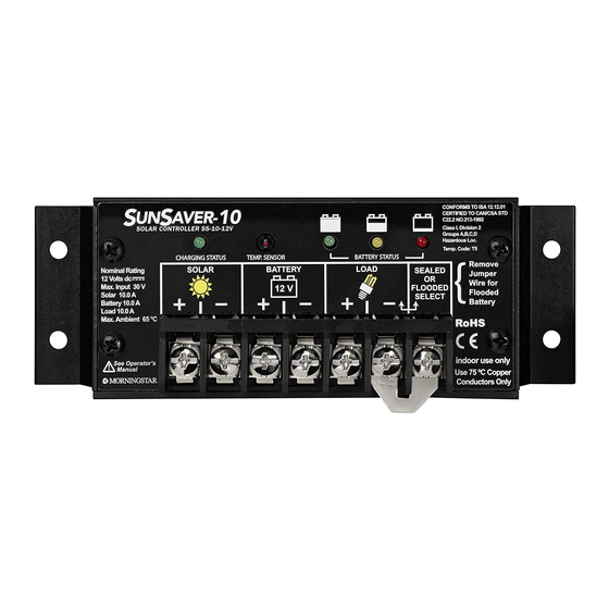
Power terminations for system Solar, Battery, and Load connections. 3 - Battery Select Jumper A removable jumper to select the battery type. 4 - Local Temperature Sensor Measures ambient temperature. Battery regulation is adjusted based on ambient temperature changes. 2.0 GENERAL INFORMATION MORNINGSTAR CORPORATION... -
Page 7: Regulatory Information
6 - Mounting Holes interference that may cause undesired operation. Four (4) mounting holes Changes or modifications not expressly approved by Morningstar for compliance could void the user’s authority to operate the equipment. 2.3 Regulatory Information Note: This equipment has been tested and found to comply... -
Page 8: Installation Instructions
The following instructions refer to a singular battery, but it is implied that the battery connection can be made to either one battery or a group of batteries in a battery bank. MORNINGSTAR CORPORATION 2.0 GENERAL INFORMATION... -
Page 9: User Selections
Slow Switching. See Figure 2d. 4. Tape the cut ends with electrical tape to prevent contact with the faceplate. 5. Replace the faceplate and secure with the four screws. Figure 2a. Removing the Battery Select jumper. MORNINGSTAR CORPORATION 3.0 INSTALLATION INSTRUCTIONS... -
Page 10: Mounting
Place the SunSaver in the location where it will be mounted. Verify that there is sufficient room to run wires and that there is ample room above and below the controller for air flow. Figure 2d. Cut the Regulation Select wire loop. MORNINGSTAR CORPORATION 3.0 INSTALLATION INSTRUCTIONS... -
Page 11: Wiring
NE S’AGISSE D’UN EMPLACEMENT NON DANGEREUX. CAUTION: Unit has no battery removal protection. Disconnecting battery during charging may cause a brief spike in load voltage (above the 15V regulation limit) which may damage sensitive equipment. MORNINGSTAR CORPORATION 3.0 INSTALLATION INSTRUCTIONS... - Page 12 Keep the breaker in the open (disconnected) position at this time. If wiring the load connection to a distribution panel, each load circuit should be fused separately. The total load draw should not exceed the the SunSaver’s maximum load rating. MORNINGSTAR CORPORATION 3.0 INSTALLATION INSTRUCTIONS...
- Page 13 Keep the breaker in the open (disconnected) position at this time. CAUTION: Unit has no battery removal protection. Disconnecting battery during charging may cause a brief spike in load voltage (above the 15V regulation limit) which may damage sensitive equipment. MORNINGSTAR CORPORATION 3.0 INSTALLATION INSTRUCTIONS...
- Page 14 Higher voltage PV modules designed for on-grid PV câbles du système. applications should not be used with the SunSaver or any PWM controller. Only use high voltage modules with maximum power point tracking (MPPT) controllers. MORNINGSTAR CORPORATION 3.0 INSTALLATION INSTRUCTIONS...
- Page 15 UL / ETL. Begin by removing the two (2) lower faceplate screws as Last, secure the terminal cover with the two (2) screws shown in figure 8a. Set the screws aside. included with the cover. MORNINGSTAR CORPORATION 3.0 INSTALLATION INSTRUCTIONS...
-
Page 16: Operation
Observe that the Battery Status LEDs blink in sequence one time. If the SunSaver does not power up or a flashing LED error sequence exists, refer to Section 5.0 Troubleshooting. MORNINGSTAR CORPORATION 3.0 INSTALLATION INSTRUCTIONS... -
Page 17: Battery Charging Information
See Section 5.1 Error Indications for more information. After the battery is fully charged the SunSaver reduces the battery voltage to a float charge which is sometimes called a trickle charge. Depending on battery history, the battery remains in the MORNINGSTAR CORPORATION 4.0 OPERATION... -
Page 18: Load Control Information
If the terminal low voltage disconnect event will occur soon. The amount of voltage of the battery is greater than 1 Volt, the SunSaver time between a green SOC indication and load disconnect MORNINGSTAR CORPORATION 4.0 OPERATION... -
Page 19: Protections
• The SunSaver will go straight to LVD on start-up if the (Charge Status LED: off) Fully protected against reverse battery voltage is at or below 11.7V / 23.4V. solar connection. No damage to the controller will result. Correct the mistake to resume normal operation. MORNINGSTAR CORPORATION 4.0 OPERATION... -
Page 20: Inspection And Maintenance
This is a critical error. Contact your • Verify that all wire clamps and tie-downs are secure. authorized Morningstar dealer for service. • Check that the controller is mounted in a clean, protected environment; free of dirt, insects, nests, Damaged Internal Temperature Sensor and corrosion. -
Page 21: Troubleshooting
R&G - Y Sequencing • Self-test Error R - Y - G Sequencing settings. NOTE: If the SunSaver model is SS-6-12V or SS-10-12V Note: (no load control feature), the controller may be damaged. LED error indications can be interpreted as follows: “R - G sequencing”... -
Page 22: Warranty And Claim Procedure
FIVE (5) years from the date of shipment to the warranty issues quickly. original end user. Morningstar will, at its option, repair or replace any such defective products. 3. If supplier is unable to address the issue, please contact WARRANTY EXCLUSIONS AND LIMITATIONS Morningstar by e-mail (support@morningstarcorp.com) with:... - Page 23 Flash R to R 11.5 Storage temperature -55°C to +80°C Humidity 100% N.C. Note: Multiply x2 for 24 Volt systems. Enclosure IP10 (indoor) Note: Only SunSavers with load control display the Flashing Red LED indication. MORNINGSTAR CORPORATION 7.0 TECHNICAL SPECIFICATIONS...
- Page 24 30 Amps ° 3% Voltage drop, Annealed copper wire at 20 * per 2011 NEC NFPA 70, Article 240. For copper wire only. * Refer to the wire charts on page 47 for appropriate wire size. MORNINGSTAR CORPORATION 7.0 TECHNICAL SPECIFICATIONS...
- Page 25 THIS PAGE IS LEFT BLANK INTENTIONALLY MORNINGSTAR World’s Leading Solar Controllers & Inverters www.morningstarcorp.com Specifications subject to change without notice. Designed in the U.S.A. Assembled in Taiwan. © 2017 Morningstar Corporation MS-001272 v3.3...
Need help?
Do you have a question about the SS-10-12V and is the answer not in the manual?
Questions and answers