Table of Contents
Advertisement
Advertisement
Table of Contents
Troubleshooting

Related Manuals for Morningstar Sunlight SL-10


Summary of Contents for Morningstar Sunlight SL-10
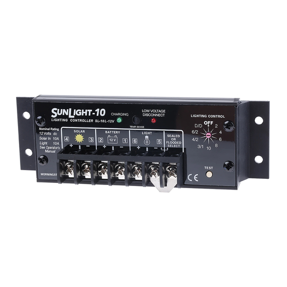
- Page 1 ’ PERATOR ANUAL SUNLIGHT MODELS INCLUDED IN THIS MANUAL SL-10 • 10A / 12V SL-10-24V • 10A / 24V SL-20 • 20A / 12V SL-20-24V • 20A / 24V 1098 Washington Crossing Road Washington Crossing, PA 18977 USA Website: ww.morningstar.com...
- Page 2 S O L A R L I G H T I N G C O N T R O L L E R TEMP. SENSE 12 Volts SEALED 10A Solar 1.00 FLOODED 10A Load – – – SELECT (25) 2.18 (55) TEST MORNINGSTAR 4 MOUNTING HOLES ø0.20 (5.0) inches (mm) 1.32 (34)
-
Page 3: Table Of Contents
CONTENTS ..........1 ENERAL NFORMATION ........2 MPORTANT AFETY NSTRUCTIONS .......... 2 UICK TART NSTRUCTIONS ........3 IGHTING ONTROL PTIONS LED I ..............4 NDICATORS ..........4 NSTALLATION NSTRUCTIONS 6.1 Ratings and Limits ..........4 6.2 Polarity Protection ..........5 6.3 Brownout Protection .......... -
Page 4: Important Safety Instructions
will help you to make full use of the many advantages the SunLight can provide to your solar lighting system. 2.0 IMPORTANT SAFETY INSTRUCTIONS • SAVE THESE INSTRUCTIONS—This manual contains important instructions that should be followed during installation and main- tenance of the SunLight controller. -
Page 5: Lighting Control Options
10A Light – – – TEST MORNINGSTAR MADE IN USA Connect the LIGHT last. If the red LED indicator lights, the bat- tery capacity is low and should be charged before completing the system installation (Refer to Section 6.4). The controller is shipped with a terminal jumper installed. This sets the controller for charging SEALED batteries. -
Page 6: Led Indicators
5.0 LED INDICATORS LED: REEN The green LED indicator will light whenever sunlight is avail- able for battery charging. The green LED will turn off at night. Because the SunLight uses a PWM constant voltage charging process, there is usually some amount of energy going into the battery at all times. -
Page 7: Polarity Protection
• Because the SunLight is a series controller, the PV current rating is specified at the PV array’s peak power (Ipp). The SunLight does NOT short the PV array for regulation, and it is not necessary to derate the controller for short-circuit current (Isc) as is commonly done with shunt controllers. - Page 8 • Tighten each terminal clamping screw to 20 inch-pounds of torque. • The SunLight is designed to regulate power from a PV array. Other generators can be connected directly to the battery, however, with no effect on the SunLight. • Do not connect any system wires (Solar, Battery, Light) to the SEALED OR FLOODED SELECT terminal.
- Page 9 If the battery voltage is below 11.7 (or 23.4) volts, the load has been automatically disconnected due to a very low battery charge condition, and the battery must be recharged. A battery below 10 volts may not start the microcon- troller properly.
-
Page 10: Operation
8. For safety and the most effective lightning protection, the nega- tive conductor of the battery should be properly grounded. The SunLight connects the PV-negative, Battery-negative and Load- negative internally per UL recommendations. No switching is done in the negative current path. 7.0 OPERATION 7.1 S ELECT... -
Page 11: Operator Tasks
Switch # of Switch # of Setting Flashes Setting Flashes Rotate the rotary switch one full cycle if there is an incorrect or no LED flash (except for OFF setting). b. Turn system lights on Pressing the TEST button will turn the system lights on to verify cor- rect installation or for troubleshooting a system problem. - Page 12 • Battery Charge Regulation SunLight uses an advanced series PWM charge control for con- stant voltage battery charging. A true 0 to 100% PWM duty cycle is very fast and stable for positive charge control under all system conditions. • Day-Night Transition The SunLight uses the solar array to detect day and night.
- Page 13 This will continue as long as sufficient power is available from the PV array. • Parallel Controllers Morningstar controllers work very well in parallel configurations. No blocking diodes are required. The only constraint is that each controller must have an independent and separate PV subarray and load.
-
Page 14: Inspection And Maintenance
• Set the power supply voltage to 15 volts DC or less for 12V systems, and 30 volts DC or less for 24V systems. • Connect only one power supply to the controller. For more information on testing SunLight controllers with a power supply, contact the Morningstar Website for test procedures. -
Page 15: Troubleshooting
8.2 T ROUBLESHOOTING The SunLight is very rugged and designed for the most extreme operating conditions. Most PV system problems will be caused by connections, voltage drops, and loads. Troubleshooting the SunLight controller is simple. Some basic troubleshooting procedures are listed below. 1. - Page 16 2. B ATTERY OLTAGE a. First check the operating conditions to confirm that the voltage is higher than specifications. Consider the temperature compensa- tion of the controller’s PWM setpoint. For example, at 0°C the controller will regulate at about 15.1 volts (for 12 volt flooded batteries).
Need help?
Do you have a question about the Sunlight SL-10 and is the answer not in the manual?
Questions and answers