Table of Contents
Advertisement
Quick Links
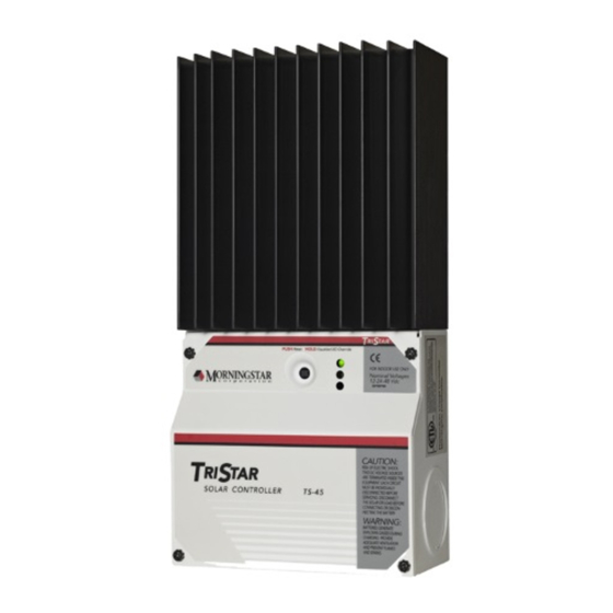
Solar Charging System Controller
Installation, Operation and
For the most recent manual revisions, see the version at:
Maintenance Manual
www.morningstarcorp.com
MAXIMUM POWER POINT TRACKING
.....
Solar Battery Charging
.....
Load Control
.....
Diversion Control
www.morningstarcorp.com
TM
MODELS
TS-45
TS-60
TS-60M
Advertisement
Table of Contents

Subscribe to Our Youtube Channel
Related Manuals for Morningstar TriStar TS-60M


Summary of Contents for Morningstar TriStar TS-60M
- Page 1 Solar Charging System Controller Installation, Operation and Maintenance Manual For the most recent manual revisions, see the version at: www.morningstarcorp.com MAXIMUM POWER POINT TRACKING ..Solar Battery Charging ..Load Control ..Diversion Control www.morningstarcorp.com MODELS TS-45 TS-60 TS-60M...
-
Page 2: Table Of Contents
Table of Contents Important Safety Instructions ..............1 1.0 TriStar Description ................7 Versions and Ratings ..............7 Operating Modes ............... Adjustability ................General Use ................Safety and Regulatory Information ..........Optional Accessories................11 Installation ....................12 General Information ..............12 Installation Overview ..............Installation Steps .............. -
Page 3: Important Safety Instructions
Load & Lighting Control ............... 42 IMPORTANT SAFETY INSTRUCTIONS 5.1 General Load & Lighting Control Notes..........42 5.1.1 Inductive Loads............. 42 SAVE THESE INSTRUCTIONS. 5.1.2 Parallel TriStars..............42 5.1.3 Reverse Polarity..............42 This manual contains important safety, installation, operating and mantenance instructions for the TriStar-PWM solar controller. 5.2 Load Control Settings .............. - Page 4 • The battery bank must be comprised of batteries of same type, make, and . . . WARNING: RISK OF ELECTRICAL SHOCK. age. NO POWER OR ACCESSORY TERMINALS ARE ELECTRICALLY ISOLATED FROM DC INPUT, AND MAY BE ENERGIZED WITH HAZARD- •...
- Page 5 le fonctionnement. PRUDENCE: Lorsque le remplacement des piles, utilisez correctement nombre spécifié, • Utilisez des outils isolés pour travailler avec les batteries. tailles, types et les évaluations basées sur conception de • Évitez le port de bijoux pendant l’installation. système et d’application. •...
-
Page 6: Tristar Description
• Entretien des batteries devrait être effectué ou supervisé, par un personnel bien 1.0 TriStar Description informé sur les piles et les précautions de sécurité appropriées. The TriStar is a technically advanced solar system controller. There are three • Soyez très prudent quand vous travaillez avec des grandes batteries au plomb. operating modes programmed into each TriStar. -
Page 7: Adjustability
TriStar, and the other is in the wiring compartment. The a personal computer will enable extensive adjustments using PC software year and week of manufacture are the first four digits of the serial number. For from Morningstar’s website. example: year... -
Page 8: Safety And Regulatory Information
A modular unit that uses a USB-B plug, usually from a USB A-B This Class B digital apparatus complies with Canadian ICES-003. computer cable, and an RJ-11 plug to connect with a Morningstar controller’s MeterBus port, for monitoring and programming using Cet appareil numerique de la classe B est conforme a la norme NMB-003 MSView PC software. -
Page 9: Installation
If the solar array exceeds the current rating of the controller, multiple TriStars can be installed in parallel. Additional parallel controllers can also be added in the future. The load controllers cannot be used in parallel. To parallel diversion controllers, refer to Morningstar’s website. – –... -
Page 10: Installation Steps
Recommended tools: • wire cutter • phillips screwdrivers • wire stripper • torque wrench (to 50 in-lb) • slotted screw drivers • flashlight Hydro — Before starting the installation, review these safety notes: Wind – – — • Do not exceed a battery voltage of 48V nominal (24 cells). Do not use a Solar + –... - Page 11 REMARQUE : Les instructions ci-dessous concernent la charge de batteries solaires. Reportez-vous à l’Annexe 1 pour les réglages du commutateur DIP de contrôle de charge et à l’Annexe 2 pour les réglages du commutateur DIP de contrôle de charge de diversion. The DIP switches are located behind the negative power terminals.
- Page 12 The DIP switch settings described below are for Solar Battery Charging only. DIP Switches Number 2,3 - System Voltage: Load and Diversion switch settings can be found in Appendixes 1 and 2. Voltage Switch 2 Switch 3 Auto The DIP switches are shipped in the OFF position. With the switches in the OFF position, the following functions are present: Switch Function...
-
Page 13: Remote Temperature Sensor
This remote temperature probe should not be installed for dc load control. Figure 2.8 - Step 3 DIP Switch # 7 The optional Morningstar RTS is connected to the 2-position terminal located In the Auto Equalization mode (switch #7 On), battery equalization will between the push-button and the LEDs. -
Page 14: Battery Voltage Sense
AVERTISSEMENT: Risque d’incendie. The maximum length allowed for each battery voltage sense wire is 30 meters (98 ft). Si non Capteur de température distant (RTS) est connecté, utilisez le The battery sense terminal has polarity. Be careful to connect the battery TriStar-PWM moins de 3m (10 pi) de les batteries. - Page 15 NOTES: • The specified wire length is for a pair of conductors from the solar, load or battery source to the controller (1-way distance). – – • Figures are in meters (m) and feet (ft). • For 24 volt systems, multiply the 1-way length in the table by 2. + –...
-
Page 16: Rs-232 Adjustments
The TriStar must be powered from the battery to enable use of the RS-232 / 3.2 Push-button PC computer connection. Refer to Section 7.0 for using the RS-232 and Morningstar’s PC software to change set-points or confirm the installation In the battery charging mode (both solar and diversion), the following settings. -
Page 17: Led Indications
3.3 LED Indications LOAD & LIGHTING CONTROL Valuable information can be provided by the three LEDs in the front cover. 2. Load Status Although there are many different LED indications, they have similar patterns to make it easier to interpret each LED display. Consider as three groups of indications: General Transitions // Battery or Load Status // Faults. - Page 18 Solar high temperature: REMARQUE : Il existera toujours un délai de 10 secondes entre les (R-Y sequencing) When the heatsink temperature limit is reached, the TriStar will tentatives de reconnexion des commutateurs TEC. Même si begin reducing the solar input current to prevent more heating. If the controller l’alimentation est déconnectée, le TriStar attend la fin des 10 secondes continues heating to a higher temperature, the solar input will then be disconnec- quand l’alimentation est rétablie.
-
Page 19: Data-Logging
Remote temperature sensor (RTS) failure: AVERTISSEMENT: RISQUE DE CHOC ÉLECTRIQUE. (R/Y-G/Y) If a fault in the RTS (such as a short circuit, open circuit, loose terminal) occurs after the RTS has been working, the LEDs will indicate a ON ALIMENTATION OU AUX BORNES D’ACCESSOIRES failure and the solar input is disconnected. -
Page 20: Pwm Battery Charging
Refer to “Why PWM?” on Morningstar’s website for more information 0.15 volts for a 12 volt battery. This is a substantial change in the charging of the battery, and a remote temperature sensor is recommended to adjust Selecting the best method for charging your battery together with a good charging to the actual battery temperature. -
Page 21: Temperature Effects & Battery Voltage Sense
A. Battery Type - These are generic lead-acid battery types. See Section 9.0 for more Float information about battery types and appropriate solar charging. Float is less affected by temperature changes, but it may also undercharge or gas too much depending on how much the temperature changes. B. -
Page 22: Equalization
NOTE: Excessive overcharging and gasing too vigorously can damage These voltage drops will cause some undercharging of the battery. The the battery plates and cause shedding of active material from the plates. controller will begin PWM absorption, or limit equalization, at a lower battery An equalization that is too high or for too long can be damaging. -
Page 23: Preparation For Equalization
4.4.3 Preparation for Equalization 4.5 Float First, confirm that all your loads are rated for the equalization voltage. When a battery becomes fully charged, dropping down to the float stage will Consider that at 0˚C (32˚F) the equalization voltage will reach 16.05V in a 12V provide a very low rate of maintenance charging while reducing the heating system (64.2V in a 48V system) with a temperature sensor installed. -
Page 24: Load & Lighting Control
If a heavy load must be connected to the TriStar's load terminals e.g. for LVD on-on-on Custom Custom Custom purposes, contact your dealer or Morningstar Tech Support for a design solution. Table 5.1 5.1.2 Parallel TriStars The table above describes the standard selectable LVD battery voltages for Two or more TriStars should never be put in parallel for a large load. -
Page 25: Lvd Warning
CAUTION: If the TriStar’s rating is exceeded and the controller dis- The amount of time it takes to transition through the LEDs to LVD can vary connects the diversion load, Morningstar will not be responsible for greatly for different systems. It may be worthwhile to measure the time it takes any damage resulting to the system battery or other system compo- for your system to transition from one LED state to the next. -
Page 26: Battery Charging References
All values are @25ºC (77ºF). 6.4 Selecting the Diversion Load It is critical that the diversion load be sized correctly. If the load is too small, it Time Max. cannot divert enough power from the source (wind, hydro, etc). The battery Until Time Equalize... -
Page 27: Load Power Ratings
NOTE: Because the battery can supply any size load, the peak load Nominal Voltage TriStar-45 TriStar-60 current is not limited by the source (hydro or wind rating). The diversion 2700W at 60V 3600W at 60V load’s power rating is the critical specification for reliable battery 1350W at 30V 1800W at 30V charging. -
Page 28: Nec Requirements
6.5.2 150 Percent Rating Consult Morningstar’s website for the latest TriStar PC software and instructions. The current rating of the diversion load must be at least 150% of the TriStar 7.1 Connection to a Computer source current rating. -
Page 29: Changing Set-Points
8.0 Self-Test / Diagnostics 7.3 Changing Set-points Follow the instructions in the PC software. The TriStar performs a continuous self-test to monitor controller and system operation. Detected problems are classified as either faults or alarms. CAUTION: There are few limits to the changes that can be made. Typi cally, faults are problems that stop the normal operation of the controller It is the responsibility of the operator to be certain all changes are and require immediate attention. -
Page 30: Troubleshooting Solar Charging
9.0 Battery Information 8.2 Troubleshooting Solar Charging • Over-charging or under-charging the battery The standard battery charging programs in the TriStar controller, as described • DIP switch settings may be wrong in Section 4.2, are typical charging algorithms for three battery types: •... -
Page 31: Flooded Batteries
is important to never exceed the manufacturer’s maximum charging voltages. Typically, a gel battery is recharged in cycling applications from 14.1V to Lead-Antimony: 14.4V. The gel design is very sensitive to overcharging. Antimony cells are rugged and provide long service life with deep discharge capability. -
Page 32: Warranty
60 A workmanship for a period of FIVE (5) years from the date of shipment to the • Current ratings — Load Control original end user. Morningstar will, at its option, repair or replace any such TS-45: 45 A defective products. - Page 33 BATTERY CHARGING STATUS LEDs Appendix 1 — Load & Lighting Control DIP Settings 13.3 to PWM 13.0 to 13.3 V 12.65 to 13.0 V 12.0 to 12.65 V 0 to 12.0 V 1 2 3 4 5 6 7 8 Note: Multiply x 2 for 24V systems, x 4 for 48V systems Note: The LED indications are for charging a battery.
- Page 34 The DIP switch settings described below are for Load and Lighting Control only. The DIP switch selectable voltages are for 12V, 24V or 48V lead-acid batteries. Although the “auto voltage” selection is very dependable, it is recommended to use The DIP switches are shipped in the OFF position. The OFF settings will operate as the DIP switches to secure the correct system voltage.
- Page 35 DIP Switches Number 4,5,6 - Lighting Control Algorithm: DIP Switch Number 7 - Must be OFF: Switch 7 For Lighting Control mode, set the DIP switches 4,5,& 6 according to the table below. 1 2 3 4 5 6 O FF after before Sunset...
-
Page 36: Appendix 2 - Diversion Charge Control Dip Switchsettings
Appendix 2 - Diversion Charge Control DIP Switch Settings the ON position, Diversion Charge Contol is set. The OFF settings will operate as follows: The Diversion Charge Control DIP function adjustments: Switch Function Must be ON to set Diversion Control 2, 3 Auto voltage selected 4, 5, 6... - Page 37 DIP Switches Number 4,5,6 - Diversion Charge Control: DIP Switch Number 8 - Battery Equalization: Battery Type PWM Switch 4 Switch 5 Switch 6 Equalize Switch 8 13.8 Manual 14.0 Auto 14.2 14.4 14.6 Manual 14.8 1 2 3 4 5 6 7 15.0 Custom Automatic...
-
Page 38: Appendix 3 - Led Indications
Appendix 3 - LED Indications 3. Faults & Alarms LED Display Explanation: • Short circuit - solar/load R/G - Y sequencing G = green LED is lit • Overload - solar/load R/Y - G sequencing Y = yellow LED is lit •... -
Page 39: Certifications
, MeterBus are trademarks of Morningstar Corporation MODBUS and MODBUS TCP/IP are trademarks of Modbus IDA. www.modbus-ida.org © 2017 Morningstar Corporation. All rights reserved. MS-001156 v4.4 C E R T I F I C A T I O N S...
Need help?
Do you have a question about the TriStar TS-60M and is the answer not in the manual?
Questions and answers