Table of Contents
Advertisement
Service Manual
JP-33
Maintenance and Technical Support
JP-33 SERVICE MANUAL
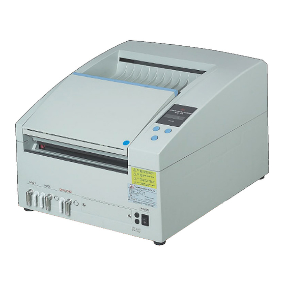
Automatic Film Processor
JUNGWON PRECISION IND. CO., LTD
Woolim e-Biz center #608,170-5, Kuro-3-dong,
TEL : 82-2-2108-2580 FAX : 82-2-2108-1180
22-36 Harman Street, Ridgewood, NY 11385
TEL: 01-718-417-3020
- -
1
Revision 5.03
Issue: 2004/04/01
Corporate:
www.jpi.co.kr
Kuro-gu, Seoul, Korea, 152-847
U.S. Office:
JPI AMERICA, INC
www.jpiamerica.com
Fax: 01-718-417-6641
Advertisement
Table of Contents
Troubleshooting

Summary of Contents for JPI JP-33
- Page 1 JP-33 SERVICE MANUAL Revision 5.03 Issue: 2004/04/01 Service Manual JP-33 Automatic Film Processor Maintenance and Technical Support Corporate: JUNGWON PRECISION IND. CO., LTD www.jpi.co.kr Woolim e-Biz center #608,170-5, Kuro-3-dong, Kuro-gu, Seoul, Korea, 152-847 TEL : 82-2-2108-2580 FAX : 82-2-2108-1180 U.S. Office: JPI AMERICA, INC www.jpiamerica.com...
- Page 2 This chapter provides instructions for cleaning and preventive maintenance of the JP33, and explains how users may keep the processor in optimal condition. Only experienced technicians should install the JP-33. The technicians who install the unit should review the JP-33 Instruction Manual before installation and should strictly follow all guidelines of the manual.
- Page 3 JP-33 SERVICE MANUAL Maintenance Record X-Ray Film Processor JP-33 Term Code: D – Daily, W – Weekly M – Monthly, Y - Yearly Date of (Jan, Feb, March, April, May, June, July, Aug, Oct, Sep, Nov, Dec,) Year 20____ Check Item...
- Page 4 JP-33 SERVICE MANUAL Maintenance Program - Cleaning Cleaning Cleaning is one of the most important factors in the maintenance program. It is very important for proper operation. Stains or contamination on the unit from water or chemicals may cause damage and corrosion. It may also seriously affect the unit’s performance, which may deteriorate image quality.
- Page 5 JP-33 SERVICE MANUAL Maintenance Program - Cleaning Weekly Cleaning Caution! When cleaning tanks and roller, do not use any abrasive material that can damage the surface. Caution! When removing the rack assembly from the unit, make sure the unit is turned off. Do not spill chemicals or water into other tanks or onto other parts of the unit, such as the control panel.
- Page 6 JP-33 SERVICE MANUAL Maintenance Program - Cleaning 3. Cleaning the drain filter of the DEV, FIX, WASH tanks A. In the event there is trouble with the drain filters in the tanks (clogging or obstructions by leftovers), problems with the circulation and replenishment of the chemicals may occur. This may accelerate contamination of chemicals and can rapidly increase or decrease the temperature of the chemistry.
- Page 7 JP-33 SERVICE MANUAL Maintenance Program - Cleaning Monthly Cleaning All rack assemblies and tanks must be cleaned thoroughly every month. This procedure may take up to two hours. Caution! Make sure unit is turned off before performing monthly cleaning. 1. Clean the DEV, FIX, WASH racks A.
- Page 8 JP-33 SERVICE MANUAL Maintenance Program - Inspection Preventative maintenance Daily Inspection 1. Check the tank levels Make sure that the chemistry inside the tanks is at the appropriate level. Also make sure to check the level of the replenishment tanks.
- Page 9 JP-33 SERVICE MANUAL Maintenance Program - Checking and Inspect Monthly Inspection 1. Check the hoses, clamps and plumbing -Do not tighten the hose clamps too much. Clamps that are too tight may cut hose and cause leakage, which may result in damage to pumps and electrical components.
- Page 10 JP-33 SERVICE MANUAL Maintenance Program - Change Chemical When & How to Replace Chemicals Important: The chemistry’s condition is important for proper film processing. Exhausted and/or contaminated chemistry will lead to poor images. Since the processor is used in the final stage of generating an image, it is normally blamed for poor image quality, overlooking the chemistry.
- Page 11 JP-33 SERVICE MANUAL Maintenance Program - Change Chemical 3) Clean processor before adding new chemistry Cleaning tanks (Close drain valves) With lukewarm water rinse each tank. Drain the used water by opening the drain valves. Dry all tanks with a lint-free cloth Close the drain valve after cleaning all the tanks.
- Page 12 JP-33 SERVICE MANUAL Maintenance Program - Change 6) Install replenishment tanks Place replenishment tanks in their proper location under the processor. Connect hoses or insert hoses into tanks. Refer to color codes and picture to prevent error. Color codes of hoses used with the processor...
- Page 13 JP-33 SERVICE MANUAL Technical Support This chapter provides technical supports for technical service personnel. Part I. Trouble Shooting. -------------------------------------- page 14 Part II. Developer-Temperature calibration. ---------------- page 30 Part III. AC-Power voltage setting (220/240V). ----------- page 31 Part IV. How to replace key parts. --------------------------- page 35 Part V.
- Page 14 JP-33 SERVICE MANUAL Technical Support - Trouble Shooting PART I -Trouble Shooting Please refer to this trouble-shooting guide before contacting technical support. This guide provides possible causes for the problems you are experiencing. Some simple checks or minor adjustments on your part may eliminate the problems and restore proper operation.
- Page 15 JP-33 SERVICE MANUAL Technical Support - Trouble Shooting 3. Mechanical problems 3-1. The unit squeaks during operation. 3-2. Rack jumps and rattles. 3-3. Wrinkled film. 3-4. Film exits unit at an angle. 4. Poor image quality. 4-1. High contrast. 4-2.
- Page 16 JP-33 SERVICE MANUAL Technical Support - Trouble Shooting Troubleshooting general problems 1-1. Problem Cannot insert film, or unit does not activate when film is inserted. Check Film Sensor manually. Film Sensor is located inside the Feed Tray. : It can easily be seen and accessed when feed tray cover is opened.
- Page 17 JP-33 SERVICE MANUAL Technical Support - Trouble Shooting Check to see if main motor is operating. Remove the top-cover and check if the motor is operating. : If motor is not functioning properly, contact tech support. Check if DEV Rack is placed in tank properly.
- Page 18 JP-33 SERVICE MANUAL Technical Support - Trouble Shooting 1.3 Problem Scratches or Markings on developed Film. A. There are white or black lines parallel to film feed direction. Check if the Film-Guide is contaminated, damaged or dislocated. Clean the Film Guide or replace the damaged Film Guide.
- Page 19 The RPL is factory set at “00”: RPL “00” is for standard processing conditions. JP-33 Film Processor is set-up to replenish Developer and Fixer according to the following chart. Please program the RPL time accordingly to required specifications for your applications.
- Page 20 JP-33 SERVICE MANUAL Technical Support - Trouble Shooting 1.7 Problem Chemicals are being supplied without stopping. Check the operation of the Film Detection Sensor. Check feed sensor, refer to trouble shooting section 1.2. 1.8 Problem Film is not drying Check if the Dryer air is warm or cold.
- Page 21 JP-33 SERVICE MANUAL Technical Support - Trouble Shooting Troubleshooting for Electrical problems When dealing with electrical problems make sure to unplug unit from power supply. If the operator does not have professional knowledge in electricity, don’t investigate or take any actions other than described below.
- Page 22 JP-33 SERVICE MANUAL Technical Support - Trouble Shooting 2.3 -Unstable operation the unit turns on and off. : Or the display board blinks Check if there is a voltage or a current change? Main power supplied may be lowered temporarily. Turn off the power for 2 or 3 minutes and resume operation.
- Page 23 JP-33 SERVICE MANUAL Technical Support - Trouble Shooting 2.7 -Developer display temperature not the same as actual temperature. Are there volatile changes in environment (: room temperature)? If temperature in dark room is unstable, wait until the temperature is stabilized and recheck it.
- Page 24 JP-33 SERVICE MANUAL Technical Support - Trouble Shooting 2.9- Dry Heater does not work. Is there any change in voltage? REFER TO TROUBLE SHOOTING SECTION 2.3 Dry Heater is defective. If the heater is malfunctioning due to dry heater temperature fuse or thermostat, contact technical support to replace heater.
- Page 25 JP-33 SERVICE MANUAL Technical Support - Trouble Shooting Troubleshooting for Mechanical problems. 3.1 The unit squeaks during operation There is noise because of friction of Main Motor Power Delivery (Power Delivery Gear). Apply lubricant or Vaseline on the Worm or Drive Gear where noise is apparent 3.2 Rack jumps and rattles.
- Page 26 JP-33 SERVICE MANUAL Technical Support - Trouble Shooting 3.3 Wrinkled film. Caused when film jams in racks. Check if the rack is bent or out of shape (: out of square). Refer to trouble shooting section 3.2 Make sure racks are positioned properly.
- Page 27 JP-33 SERVICE MANUAL Technical Support - Trouble Shooting Troubleshooting poor image quality. 4.1 High Contrast 1. Developer has too little starter. 2. Not enough water in the developer Mixture. 3. The washer temperature is too hot causing thermal (heat) contamination increasing the developer temperature.
- Page 28 JP-33 SERVICE MANUAL Troubleshooting poor image quality. 4.5 Wet film 1. The chemistry is mixed with too much hardener or too much water has been used. 2. Developer contaminated. 3. Fixer does not have hardener added to it. 4. Depleted fixer.
- Page 29 JP-33 SERVICE MANUAL Troubleshooting poor image quality. Increased base fog 1. Starter has not been added to the developer. 2. Fixer level is too low. 3. Fixer has contaminated developer. 4. Developer replenishment rate is too high. 5. Developer temperature is too high.
- Page 30 JP-33 SERVICE MANUAL Technical Support - Temperature Calibration PART II Temperature calibration instruction WARNING: DO NOT TOUCH OR ATTEMPT TO ADJUST VR2 is used for calibrating the high and low temperature of the developer and the fixer heater (In factory).
- Page 31 Before Change) AC In-Put: 110volt, 220volt After Change) AC In-Put: 220volt, 240volt JP-33 of 220voltage field area has dual AC input 220volt, 240volt. How can use? - If field AC-voltage is 210volt ~ 240volt: use 220V terminal - If field AC voltage is 240volt ~ 260volt: use 240V terminal 2.
- Page 32 JP-33 SERVICE MANUAL...
- Page 33 JP-33 SERVICE MANUAL Attach 1 : Transformer Structure...
- Page 34 JP-33 SERVICE MANUAL Attach 2 : Transformer wiring and mounting on the main PCB...
- Page 35 JP-33 SERVICE MANUAL Technical Support - How to replace key parts Part IV How to replace key parts IMPORTANT! • When replacing Before replacing any part make sure the unit is turned off. electrical parts we recommend that the unit is unplugged from power source.
- Page 36 JP-33 SERVICE MANUAL Technical Support How to replace key parts A. Replacing replenishment pump Developer and/or Fixer. NOTE : The developer and fixer replenishment pumps are identical in appearance and wiring. Identify the correct pump before execution. If the two pumps are being replaced, make sure to replace each pump separately (Remove and replace pump one and then work on pump two).
- Page 37 JP-33 SERVICE MANUAL Technical Support How to replace key parts...
- Page 38 JP-33 SERVICE MANUAL Technical Support How to replace key parts B. Replacing developer/fixer heater NOTE: The developer/fixer heater is an external inline heater. This single heater is heating both the developer and fixer. Make sure both tanks are drained before removing the heater.
- Page 39 JP-33 SERVICE MANUAL Technical Support How to replace key parts Version Revise Note: The picture of new developer heater adapt to after October 2003. DEV and FIX heating pipe new version...
- Page 40 JP-33 SERVICE MANUAL Technical Support How to replace key parts . Replacing re-circulation pumps NOTE: The developer and fixer re-circulation pumps are identical in appearance and wiring. Identify the correct pump before execution. If the two pumps are being replaced, make sure to replace each pump separately (Remove and replace pump one and then work on pump two).
- Page 41 JP-33 SERVICE MANUAL Technical Support How to replace key parts D. Replacing developer temperature sensor 1. Make sure unit is tuned off and the appropriate chemistry is drained. Note: The developer temperature sensor is located in line between the Developer heater and the processors developer inlet.
- Page 42 JP-33 SERVICE MANUAL Technical Support How to replace key parts E. Replacing dry heater Construction of Dry Heater...
- Page 43 JP-33 SERVICE MANUAL Technical Support Location of Components and Part List Part V Location of Components and Parts List 1. Location of Electrical Components 2. Location of Developer Rack Components 3. Location of Fixer Rack Components 4. Location of Washer, Dryer Rack Components...
- Page 44 JP-33 SERVICE MANUAL Technical Support Location of Components 1. Location of Electrical Components (18) (20) (16) (17) (19) Part Name Part No. Quantity Main PCB Assembly F63-23001 Terminal Block F63-21016 Main Switch F63-21013 Fuse F63-21015 SSR for Dry Heater (:110volt only)
- Page 45 JP-33 SERVICE MANUAL Technical Support Location of Components 2. Location of Developer Rack Components Right Side View Left Side View Part Name Part No. Quantity DEV rack side plate R F63-11027B DEV rack side plate L F63-11027A Spring A & C (Large type) F63-13004A &...
- Page 46 JP-33 SERVICE MANUAL Technical Support Location of Components 3. Location of Fixer Rack Components (14) Right Side View Left Side View Part Name Part No. Quantity FIX rack side plate R F63-11028B FIX rack side plate L F63-11028A Spring A & C (Large type) F63-13004A &...
- Page 47 JP-33 SERVICE MANUAL Technical Support Location of Components 4. Location of Washer, Dryer Rack Components (17) Right Side View Left Side View Part Name Part No. Quantity Wash rack side plate R F63-11029B Wash rack side plate L F63-11029A Spring A & C (Large type) F63-13004A &...
- Page 48 JP-33 SERVICE MANUAL Technical Support Location of Components 5. Location of Main Drive Shaft Components Part Name Part No. Quantity Sprocket of Main Drive Shaft F63-14007B Main Drive Shaft F63-12001 Bracket of Min Drive Shaft F63-11005 Gear Worm Wheel F63-11025...
- Page 49 JP-33 SERVICE MANUAL Technical Support - Electrical Schematic Part VI Electrical schematics Block-Diagram of Electrical Electrical Circuit Block-Diagram Electric Power -Voltage Checking (for AC Line)
- Page 50 JP-33 SERVICE MANUAL Technical Support - Electrical Schematic 2. Schematic Circuit Diagram...
- Page 51 JP-33 SERVICE MANUAL Technical Support - Electrical Schematic 3. Microprocessor sequence table BUZZER AC Power 1sec HEATER Sensor Checking FILM PROCESSOR Temp. LIMIT sensor Thermal sensor check 0.5sec check HEATER SYSTEM Checking 000℉ 00℃ ... Error ..Error ...
- Page 52 JP-33 SERVICE MANUAL Technical Support - Electrical Schematic ERROR CHECK 1. ON Temp Sensor. Reason: Open & Short a Temperature Sensor (Pt-100) Situation 1) Beep: beeping continuous. 2) Display: “DEV xxxF℃ XX℃”on LCD. Recovering 1) Tentative: MODE switches ON automatically can setting to 32’C default.
- Page 53 JP-33 SERVICE MANUAL Technical Support - Parts List PART VII JP-33 Parts List JP-33 Parts List for Assembly Section Issued: Jan. 01. 2005. New P/N Description Q'ty Specification F63-00001 Top Cover Assembly F63-11001 Top Cover 1 HIPS 401AF, Grey color...
- Page 54 JP-33 SERVICE MANUAL F63-22010B Wire 1.25 White for Film Sensor 2 Teflon φ1.25, UL F63-14017 Cable Mounted 1 ABS UL Main PCB Assembly 1 PCB Parts List (ver. 5.0) F63-23001 Main PCB Assembly F63-11013 Case of Main PCB 1 HIPS 401AF, Grey color...
- Page 55 JP-33 SERVICE MANUAL F63-22015 Wire Yellow for Dry Heater Wiring 1 Teflon φ1.25, UL F63-22011 Wire Green/Yellow for Ground 1 Teflon φ1.25, UL Blower Fan Assembly 1 ebm G2E 108-AA 01-01 F63-21002 Blower Fan F63-14004E Screw PH Tapping 4 x 16...
- Page 56 JP-33 SERVICE MANUAL 121 F63-14011A Hose Band φ12.8, Ear Clamp 4 SUS316 122 F63-14011F Hose Band φ19.5, Ear Clamp 2 SUS 316 Power Cord Assembly 1 AC250V 16A H05VV-F 123 F63-21017 Power cord w/Bushing 124 F63-13023 Bracket of AC Cord 1 SUS316 1.5t 30 x 80...
- Page 57 JP-33 SERVICE MANUAL 165 F63-43002B Cushion Sponge of Top Inside Shield 1 Sponge 5 x 380 x 10t 166 F63-43002C Cushion Sponge of Bottom Shield 2 Sponge 10 x 120 x 10t F63-00013 Film Sensor Assembly 2 LDW-1002, Seo-Il Elec.
- Page 58 JP-33 SERVICE MANUAL 212 F63-14005B Plate Washer φ4 8 SUS316 213 F63-12002 Shaft B for Rack Drive 1 SUS316 φ8 x 471.2 5 SUS316 w/Rubber 214 F63-13001 Roller-Rubber 3 SUS316 w/PVC 215 F63-13002 Roller-PVC 2 SUS316 φ8 x 33.5 216 F63-12005A...
- Page 59 JP-33 SERVICE MANUAL 263 F63-11023 Gear B of 1.5" Idle 1 PBT Black 264 F63-11024 Gear-C of 1.5" D-cut 1 PBT Black 1 PBT Black 265 F63-11025 Gear worm Wheel 266 F63-14011D 3 SUS 316, for Accessory Hose Band φ12.8, Worm Drive Clamp...
- Page 60 JP-33 SERVICE MANUAL Wash RPL Pump Type (Close Loop) F63-21005 RPL Pump for Wash 1 Iwaki KBR-3XBU3M 1 SUS316 1.5t 80 x 150 F63-13024 Bracket of Water RPL F63-21010 Solenoid Valve for Water 110volt – Siebe, 220volt - PAKER F63-14018 Nipple Φ12 "I"...
Need help?
Do you have a question about the JP-33 and is the answer not in the manual?
Questions and answers