Advertisement
Instruction Booklet IB 70-8698
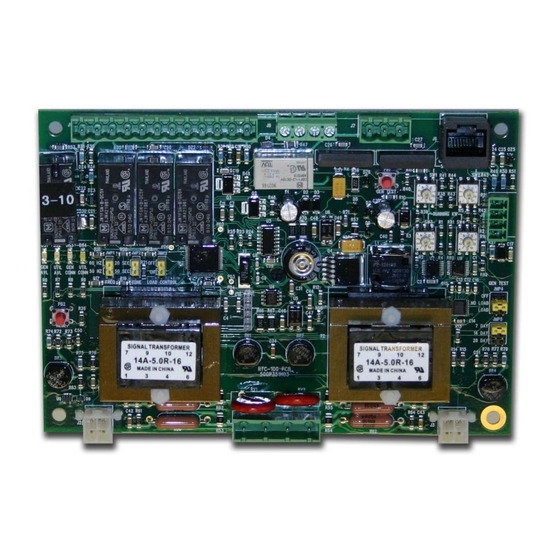
Instruction Manual for the Eaton RTC-100
Automatic Transfer Switch Controller
Contents
Description
1. Introduction . . . . . . . . . . . . . . . . . . . . . . . . . . . . . . . . . . . . . . . . . . . . . . . . . . . . . . . . . . . . . . . . . . . . . . 2
2. Hardware Description . . . . . . . . . . . . . . . . . . . . . . . . . . . . . . . . . . . . . . . . . . . . . . . . . . . . . . . . . . . . . . 5
3. Operation. . . . . . . . . . . . . . . . . . . . . . . . . . . . . . . . . . . . . . . . . . . . . . . . . . . . . . . . . . . . . . . . . . . . . . . . 6
4. Programming . . . . . . . . . . . . . . . . . . . . . . . . . . . . . . . . . . . . . . . . . . . . . . . . . . . . . . . . . . . . . . . . . . . . . 7
5. Maintenance, Troubleshooting, and Replacement . . . . . . . . . . . . . . . . . . . . . . . . . . . . . . . . . . . . . . . . 18
Effective December 2009
Page
Advertisement

Related Manuals for Eaton RTC-100


Summary of Contents for Eaton RTC-100
-
Page 1: Table Of Contents
Instruction Booklet IB 70-8698 Effective December 2009 Instruction Manual for the Eaton RTC-100 Automatic Transfer Switch Controller Contents Description Page 1. Introduction ..............2 2. -
Page 2: Introduction
In no 2. Solenoids to make the transfer of the main contacts from source event will Eaton be responsible to the purchaser or user in contract, to source. in tort (including negligence), strict liability or otherwise for any spe- cial, indirect, incidental or consequential damage or loss whatsoever, 3. - Page 3 0.5 seconds after the time delay emergency fail (TDEF) time delays grammed flexibility to address the needs of any system. It operates expires. on 240 VAC, single-phase at 50 or 60 Hz. The RTC-100 controller monitors the condition of the line voltage of both the Utility and Failsafe Generator power sources.
- Page 4 In addition, the RTC-100 controller provides status information through on-board and remote indicators. This feature provides a white LED that when lit, indicates the utility is connected. The following is a list of the features of the RTC-100 controller. 12D. Generator - Connected - EGSU Only 1. Time Delay Normal to Emergency (TDNE)
-
Page 5: Hardware Description
RTC-100 controller hardware, its nomenclature, and to list the unit’s current information that is used for the active load control portion of specifications. the RTC-100. Along the side of the controller is connector J5. This connector is currently reserved for future use. Connectors J6, J7 , 2.2 LED Indicators J8 and J9 are located along the top of the controller. -
Page 6: Operation
The RTC-100 controller provides for automatic transfer and re-trans- Undervoltage Dropout 70% of the Nominal 240 Vac Input Voltage fer from source to source. It provides a summary of the RTC-100 Undervoltage Pickup 80% of the Nominal 240 Vac Input Voltage... -
Page 7: Programming
Effective December 2009 Section 4: programming 4.1.1 Load Control Jumper Aside from the built in Active Load Control relays, the RTC-100 has 4.1 Introduction the ability to extend the loads that it can actively control. An exter- The RTC-100 controller is programmable via the five programming nal load control board, RLC-100, can be utilized so that the RTC-100 jumpers shown in Figure 2. - Page 8 (number of days) they would like the test The jumpers allow the end user to select the Gen Test (see to be run. The RTC-100 can run the exercise test every 7 calendar Figure 3) to the “OFF” , “NO LOAD” , or “LOAD” positions. This jump- days, every 14 calendar days, or every 28 calendar days.
- Page 9 Instruction Manual for the Eaton RTC-100 Instruction Booklet IB 70-8698 Automatic Transfer Switch Controller Effective December 2009 Jumpers shown in the “NO LOAD” test position “7 DAY” position Figure 3. Generator Test (Plant Exercise) Jumpers and Generator Test Pushbutton. eaton Corporation www.eaton.com...
- Page 10 Instruction Manual for the Eaton RTC-100 Instruction Booklet IB 70-8698 Automatic Transfer Switch Controller Effective December 2009 4.1.3 Reset Pushbutton If, during normal operation, a transfer (from utility to generator or from generator to utility) does NOT occur when it should, the “CONNECTED”...
- Page 11 Figures 6 and 7 . The connections must be such There are 2 relays on the RTC-100 that can be used to actively con- that the grounded side of the voltage source MUST be connected to trol up to 2 loads while connected to the generator source.
- Page 12 Instruction Manual for the Eaton RTC-100 Instruction Booklet IB 70-8698 Automatic Transfer Switch Controller Effective December 2009 Note that the Ground/ Neutral Side of the Circuits MUST Be Connected to Pins 2 and 4 Figure 6. Typical Connections of Controlled Loads – Non Thermostatically Controlled. eaton Corporation www.eaton.com...
- Page 13 Instruction Manual for the Eaton RTC-100 Instruction Booklet IB 70-8698 Automatic Transfer Switch Controller Effective December 2009 Note that the Ground/Neutral Side of the Circuits MUST Be Connected to Pins 2 and 4 Figure 7. Typical Connections of Controlled Loads – Thermostatically Controlled. eaton Corporation www.eaton.com...
- Page 14 Effective December 2009 4.1.4.2 Adjustments – Required for Automatic Load Control There are 4 potentiometers on the RTC-100 that allow the user to program the board with required information about the generator (see Figure 8). Both the RUNNING watts and the STARTING watts are required for the RTC-100 active load control to function properly.
- Page 15 If, for any reason, a controlled load is changed or replaced, the RTC-100 memory for the loads may need to be reset (as the power requirements may differ). This can be done by pressing and hold- ing the reset button for 5 seconds.
- Page 16 Instruction Manual for the Eaton RTC-100 Instruction Booklet IB 70-8698 Automatic Transfer Switch Controller Effective December 2009 RTC-100 Active Load Control Measure Load kW Are controlled load energize signal(s) present? Is this the first Is this the first measurement measurement...
- Page 17 Instruction Manual for the Eaton RTC-100 Instruction Booklet IB 70-8698 Automatic Transfer Switch Controller Effective December 2009 Measure Load kW Is the Is the Generator Generator powering the powering the Load? Load? Is Load kW < Is Load kW <...
-
Page 18: Maintenance, Troubleshooting, And Replacement
Step 8: Reapply power to the transfer switch. shooting will be performed. If the cause of malfunction is traced to an RTC-100, the unit should be replaced with a new unit. The Step 9: Place the generator control selector switch in the “AUTO”... - Page 19 Instruction Manual for the Eaton RTC-100 Instruction Booklet IB 70-8698 Automatic Transfer Switch Controller Effective December 2009 Notes: eaton Corporation www.eaton.com...
- Page 20 Eaton. Sale of product shown in this literature is subject to terms and con- ditions outlined in appropriate Eaton selling policies or other contrac- tual agreement between the parties. This literature is not intended to and does not enlarge or add to any such contract. The sole source governing the rights and remedies of any purchaser of this equipment is the contract between the purchaser and Eaton.
Need help?
Do you have a question about the RTC-100 and is the answer not in the manual?
Questions and answers