
Related Manuals for Taylor SB25


Summary of Contents for Taylor SB25
- Page 1 SERVICE MANUAL Model SB25 Blended Ice Machine Original Service Instructions 081218-S 8/12/14 (Original Publication) (Updated 3/26/15)
-
Page 3: Table Of Contents
........Model SB25 Pump-Cane A. - X82356 . - Page 4 ........... . . CAUTION: Information in this manual is intended to be used by Taylor Authorized Service Technicians only.
-
Page 5: Section 1: Introduction
Section 1: Introduction Safety Specifications General Installation Instructions Environmental Notices Model SB25 Introduction... -
Page 6: Safety
GFI to operating and serviceable equipment. The many protect against the leakage of current, built-in safety features that are part of all Taylor® installed by authorized personnel to the local equipment are aimed at protecting operators and codes. - Page 7 Some consumers are highly allergic to strawberries. In some severe cases, allergic reactions to strawberries can cause death. When blending natural strawberry products, make sure excess product is removed from the pitcher to eliminate product carryover. Model SB25 Introduction...
-
Page 8: Sb25 Specifications
SB25 Specifications Water The Model SB25 is a combination unit consisting of the Model SB24 commercial ice shaver/blender unit A 3/8” (9.5 mm) water line with minimum 55 PSI and a rinse station. (380 kPa) is required. The Model SB24 shaver/blender unit has the option INSTALL POTABLE WATER CONNECTION of metered water and liquid sugar cane dispensing. - Page 9 SB25 Specifications (Continued) Model SB25 Introduction...
-
Page 10: General Installation Instructions
ALL WIRING AND PLUMBING MUST CONFORM TO NATIONAL AND LOCAL CODES. Uncrate the unit. Inspect the unit for damage. Report any damage to the Taylor Factory immediately. INSTALL POTABLE WATER CONNECTION This unit is made using USA sizes of hardware. All WITH ADEQUATE BACK-FLOW metric conversions are approximate. - Page 11 Taylor® equipment. In all other areas of the world, equipment should be Only authorized Taylor service personnel installed in accordance with the existing local codes. should perform installation, maintenance, Please contact your local authorities.
-
Page 12: Environmental Notices
If the supply cord is damaged, it must be replaced by an authorized Taylor service technician in order to avoid a hazard. Failure to follow these instructions may result in electrocution or damage to the unit. -
Page 13: Section 2: Controls And Systems
Section 2: Controls and Systems Control Overview Keypad PC Connection General Repairs Blender Drive Board Blender Pitcher Rinse Station Model SB25 Controls and Systems... -
Page 14: Control Overview
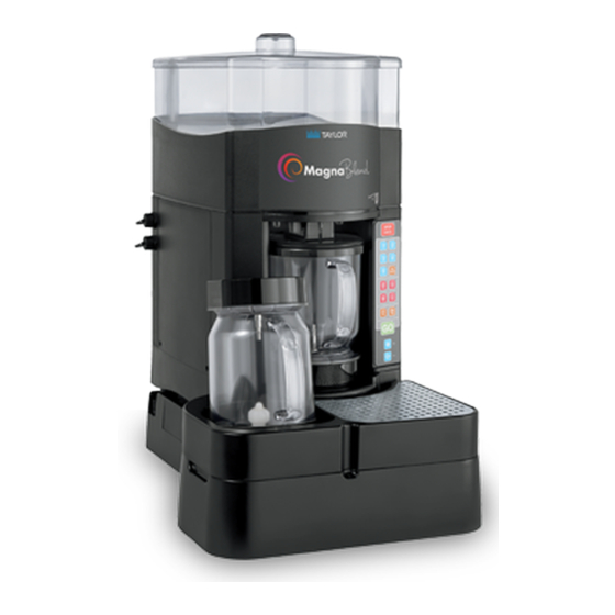
Control Overview Figure 1 Controls and Systems Model SB25... -
Page 15: Keypad
K, S, and M drink sizes. It will not make a double L drink. GO Key The GO key starts the selected drink cycle. Shaver Key and Blender Key These keys are used to manually shave ice and Figure 2 blend product. Model SB25 Controls and Systems... -
Page 16: Pc Connection
PC Connection The SB25 can be connected to a PC in order to To reset the connection select “Close Port” and manage recipes and system calibration, using the reselect. supplied software. A PC running Windows XP or greater with a USB port is required. - Page 17 Step 6 ______________________________ Select “Reset Calibration Factors” to return all values to 1.0. The SB25 unit can be calibrated using the supplied PC software or by using the manual calibration Step 7 method through the main keypad. Select “Main Menu”, select recipe settings, and select save to unit.
- Page 18 3 seconds. Press recipe 4 key to change the Cane calibration value (Model SB25, only). Step 2 When the value to be changed has been selected, it will blink at a slow rate, along with the recipe1 & 2 Press and hold the manual blend button serving size LED's.
- Page 19 Step 3 Insert the USB stick. Step 4 Switch the main power ON. Step 5 The SB25 will automatically download and save the recipe information to the unit. Step 6 Place the main power switch in the OFF position. Step 7 Remove the USB stick and reinstall the USB port cover.
- Page 20 Water Volume (oz.) – Amount of water dispensed number system setting). for each drink size. Step 8 e. Ice (oz.) – Amount of ice dispensed for each drink size. Select “Main Menu” when done. Controls and Systems Model SB25...
-
Page 21: General Repairs
Electrostatic Discharge (ESD) is the rapid discharge of static electricity from one conductor to another of a different potential. An electrostatic discharge can damage integrated circuits found in computer and communications equipment. Follow instructions where noted. Figure 7 Model SB25 Controls and Systems... - Page 22 Turn off the power switch and unplug the power cord. Step 2 Remove the right side panel screws. Step 3 Remove the right side panel. Step 4 Insert a flat screwdriver in the screw hole and bow the cover slightly. Figure 10 Controls and Systems Model SB25...
- Page 23 Remove the four nuts securing the top frame. Note: Per torque specifications, nuts are tightened to 75 inch/pounds. Figure 12 Step 10 Lift the black box and pivot it around the left front post. Step 11 Remove the black box. Figure 13 Model SB25 Controls and Systems...
- Page 24 Turn off the power switch and unplug the power cord. Step 2 Remove the ice hopper and lid. (See page 17.) Step 3 Remove the Drive Board. (See page 18.) Step 4 Figure 15 Remove the main drain assembly. (See page 19.) Controls and Systems Model SB25...
- Page 25 Step 3 Remove the ice shaver cone cover by pressing the rear tab inward and rotating the cover clockwise. Figure 17 Figure 18 Model SB25 Controls and Systems...
- Page 26 Cycle unit OFF, then ON Safety switch (hopper/cover) Ice jam in hopper Possible broken/cored out wing Shaver motor for damage Keypad error Main power board Note: See page 42 for Shaver Motor Troubleshooting Guide. Figure 20 Controls and Systems Model SB25...
- Page 27 Position the unit on its side as shown in Figure 22. Combination of drink sizes Portion of product used for drink size Blender pitcher for damage Blender motor Main power board Note: See page 42 for Blender Motor Troubleshooting Guide. Figure 22 Model SB25 Controls and Systems...
- Page 28 Be sure both tabs are locked securely into place by gently pulling down on the ice chute. Figure 24 Figure 27 Controls and Systems Model SB25...
- Page 29 Step 3 Remove the ice shaver cone cover by pressing the rear tab inward and rotating the cover clockwise. Figure 30 Step 6 Reassemble the system and check the ice volume Figure 28 for proper calibration. Model SB25 Controls and Systems...
- Page 30 Step 2 drain lines, use a small wire bottle brush available Press the toggle switch snap-in feature to remove from your Taylor Distributor. To check for leaks, the panel (keep wires connected). pour water into the top and bottom drain holes.
- Page 31 Turn off the power switch and unplug the power cord. Step 2 Remove the ice hopper and lid. (See page 17.) Step 3 Remove the main drain assembly. (See page 19). Step 4 Figure 34 Remove the Dispense PCB cover. Model SB25 Controls and Systems...
- Page 32 Remove the main drain assembly. (See page 19). Step 8 Step 5 Remove the manifold. Remove the Dispense PCB cover. Step 6 Remove the cane pump connector from the Dispense PCB. Figure 36 Figure 37 Controls and Systems Model SB25...
- Page 33 Remove the pump assembly. Figure 39 Step 10 Remove the inner jam nut holding the cane inlet connector and slide the pump inlet tube and elbow Figure 38 out through the rear of the unit. Model SB25 Controls and Systems...
-
Page 34: Blender Drive Board
DESCRIPTION KIT A.-MOTOR SHAVER DRAIN-MAIN W/SAFETY SWITCH POWER SUPPLY 115 VAC FUSE-BOARD-DRIVER I.O. LED-HEARTBEAT LED-TROUBLESHOOTING COMMUNICATION CABLE TO DISPENSE BOARD KIT A.-MOTOR BLENDER LID-IN-PLACE SENSOR IS IN ICE HOPPER SUPPORT ** PART OF 066891 HARNESS Controls and Systems Model SB25... -
Page 35: Blender Pitcher Rinse Station
This will flow for approximately six seconds and dispense allows the cycle to repeat when another pitcher is approximately 25 ounces of water. placed on the rinse station. Figure 41 Model SB25 Controls and Systems... -
Page 36: Blender Pitcher Rinse Station Repairs
Failure to Place the main power switch in the ON position. follow this instruction may result in personal injury or death from electrical shock or hazardous moving Test the triggers separately. Controls and Systems Model SB25... - Page 37 Disconnect the water supply at the quick connect fitting. Figure 48 Remove the front pan assembly. Remove and clean or replace the screen. Remove the filter cover by turning the cover to the left 1/4 turn. Reassemble the unit. Model SB25 Controls and Systems...
- Page 38 Remove the power cover by removing the screw. Figure 51 Remove the main power switch and pull the wiring harness out through the main power switch hole. Reverse the process to replace the wiring Figure 49 harness. Controls and Systems Model SB25...
- Page 39 Remove the four (4) screws holding the PC board onto the base. Install the new water valve manifold. Install the new PC board. Reconnect the tubing. Reassemble the unit. Reinstall the bottom cover. Model SB25 Controls and Systems...
- Page 40 Notes: Controls and Systems Model SB25...
-
Page 41: Section 3: Troubleshooting
Section 3: Troubleshooting General Troubleshooting Rinse Station Troubleshooting Blender Troubleshooting Model SB25 Troubleshooting... -
Page 42: General Troubleshooting
Check filter and store plumbing. Water is leaking from the unit. Poor fitting/hose connection. Check all visible fittings and ensure all hoses are fitted into the fittings properly. Cracked hose. Replace cracked hose. Broken fitting. Replace fitting. Troubleshooting Model SB25... - Page 43 The shaver motor is over Reset the unit. Use the Motor over temperature). temperature. Troubleshooting Guide to evaluate the motor and replace if necessary. Motor failure. Use the Motor Troubleshooting Guide to evaluate the motor and replace if necessary. Model SB25 Troubleshooting...
- Page 44 Recipe key #1, 2, 3, or 4 - fast blink No communication between the Check the ribbon cable (communication fault). keypad and the dispense board. connections. Replace keypad, ribbon cable, or the dispense PCB if necessary. Troubleshooting Model SB25...
-
Page 45: Rinse Station Troubleshooting
Unit is not draining. The drain line is kinked. Straighten the drain line. There is no air gap between the Provide air gap. drain line and the drain. The drain line is clogged. Unclog the drain line. Model SB25 Troubleshooting... -
Page 46: Blender Troubleshooting
If not, there is a for each measurement. If not, there is a dead short in the motor and the motor dead short in the motor and the motor should be replaced. should be replaced. Troubleshooting Model SB25... - Page 47 If jumping LID1 does not fault. Field test the motor. If the motor change the state of the error, replace is okay and the fault persists, replace the drive board. the drive. Model SB25 Troubleshooting...
- Page 48 Touchscreen as BLENDER MOTOR Touchscreen as SHAVER MOTOR LOCK. Check software version. This LOCK. Check the software version. applies to v2.98 USA; 1.30 and later This applies to v2.98 USA; 1.30 and for International. later for International. Troubleshooting Model SB25...
-
Page 49: Section 4: Parts
Section 4: Parts Warranty Explanation Exploded Views Parts List Wiring Diagram Model SB25 Parts... -
Page 50: Warranty Explanation
Taylor warrants the Parts against failure due to defect in materials or workmanship under normal use and service as follows. All warranty periods begin on the date of original installation of the Part in the Taylor unit. If a Part fails due to defect during the applicable warranty period, Taylor, through an authorized Taylor distributor or service agency, will provide a new or re-manufactured Part, at Taylor’s option, to replace the failed defective Part at no... - Page 51 Parts or the units in which they are installed repaired or altered in any way so as, in the judgment of Taylor, to adversely affect performance, or normal wear or deterioration.
-
Page 52: Taylor Company
LEGAL REMEDIES The owner must notify Taylor in writing, by certified or registered letter to the following address, of any defect or complaint with the Part, stating the defect or complaint and a specific request for repair, replacement, or other correction of the Part under warranty, mailed at least thirty (30) days before pursuing any legal rights or remedies. -
Page 53: Model Sb25 Operator Parts
Model SB25 Operator Parts (Shown with optional rinse station) E 2014 Carrier Commercial Refrigeration, Inc. Figure 54 141114 Model SB25 Parts... - Page 54 Model SB25 Operator Parts Identification ITEM DESCRIPTION PART NO. ITEM DESCRIPTION PART NO. COVER A.-HOPPER-IO 081239 GUARD-SPLASH 081122 HOPPER-IO 081238 CHUTE-SHAVER 081121 CONE-PLASTIC 065194-48 WING-PLASTIC ROTARY 081576 O-RING-1 OD X .103W 048148 KIT-BLADE-CARTDRIGE*IO 069087 (25 TO BAG) COVER-CONE-PLASTIC 065194-49 GRATE-RIGHT...
-
Page 55: Model Sb25 Internal Service Parts
Model SB25 Internal Service Parts E 2014 Carrier Commercial Refrigeration, Inc. Figure 55 150324 Model SB25 Parts... - Page 56 Model SB25 Internal Service Parts Identification ITEM DESCRIPTION PART NO. ITEM DESCRIPTION PART NO. HARNESS-POWER UNIT-IO 081897 KIT A.-MOTOR BLENDER X6519415SV COUPLING-3/8 BARB-VALVED 081886 SCREW-6-32 X 1/2 HEX HEAD 065194-50 COUPLING-BULKHD-1/4-VALV 081191 PUMP A.-CANE **SEE PAGE 57 X82356-12 PLUG A.-USB CABLE 073808 SCREW-8-32X5/8 PPH 18-8 S.S 081890...
-
Page 57: Model Sb25 Drain Assembly
Model SB25 Drain Assembly E 2014 Carrier Commercial Refrigeration, Inc. Figure 56 Model SB25 Parts... - Page 58 Model SB25 Drain Assembly Parts Identification ITEM DESCRIPTION PART NO. ITEM DESCRIPTION PART NO. COUPLING-1/4ODX1/4OD 058302 KIT A.-MOTOR SHAVER X6519416SV SCREW-8-32X5/8 PPH 18-8 SS 081890 MOUNT-MOTOR-SHAVER 081119 KIT A.-SEAL SHAFT MOTOR X6519418SV SCREW-SENSOR-CLIP 065194-55 WASHER-1/4 MED SPLIT LOCK 018954 RETAINER-SWITCH-SAFETY...
-
Page 59: Model Sb25 Front Panel
Model SB25 Front Panel E 2014 Carrier Commercial Refrigeration, Inc. Figure 57 ITEM DESCRIPTION PART NO. ITEM DESCRIPTION PART NO. PANEL-FRONT-ISLAND OASIS 081107 KEYPAD A.-FD X81887-SER KEYPAD A. X82584 BEZEL-KEYPAD 081109-1 CABLE-KEYPAD-IO 081110 SCREW-6X3/8-HWH-TYPE B 081111 Model SB25 Parts... -
Page 60: Model Sb25 Manifold 082222-12
Model SB25 Manifold 082222-12 E 2014 Carrier Commercial Refrigeration, Inc. Figure 58 ITEM DESCRIPTION PART NO. ITEM DESCRIPTION PART NO. COIL-SOLENOID VALVE 120 082222-121 REGULATOR-WATER-15 PSI 082222-122 VALVE-SOLENOID 082222-123 ELBOW-STEM-1/4 PTC X 1/4 ST 082222-127 FILTER-WATER 082222-124 082222-125 *NOT SHOWN... -
Page 61: Model Sb25 Pump-Cane A. - X82356
Model SB25 Pump-Cane A. - X82356 E 2014 Carrier Commercial Refrigeration, Inc. Figure 59 ITEM DESCRIPTION PART NO. ITEM DESCRIPTION PART NO. PUMP-DIAPHRAGM-CANE 081889-12 COUPLING-3/8 BARB-5/16 081884 ELBOW-PUMP-3/8 BARB 081885 TUBE-POLYPROPY-1/4OD 081153-12 CLAMP-HOSE-MUBEA-15MM 083290 REDUCER-90 DEG-5/16X1/4 JG 081901 HOSE-BEVERAGE 3/8 ID X 5/8 053052-4.5... -
Page 62: Rinse Station
GASKET-RINSER NOZZLE-IO 083473 PORT-DRAIN 081182 RING-RETENTION 083459 O-RING-1-7/8OD X .070W 081189 FITTING-ELBOW 250 TUBE 082341 SCREW-8-32X1/2PPHD-SS 081233 PCB A.-STATION-RINSE-IO X81188-SER SWITCH-A.RCKR-SPST 083331 SCREW-4-40X3/8 PAN HD SS 600135 COUPLING-BULKHD-1/4-VALV 081191 SCREW-8-32X1/2 PPHD-SS-N 081233 NOZZLE-SPRAY-RINSE 066814 FOOT-RUBBER-IO 081185 140916 Parts Model SB25... -
Page 63: Rinse Station Manifold
Rinse Station Manifold 082222-05 E 2014 Carrier Commercial Refrigeration, Inc. Figure 61 ITEM DESCRIPTION PART NO. ITEM DESCRIPTION PART NO. ELBOW-STEM-1/4 PTC X 1/4 ST 082222-127 REGULATOR-WATER-75 PSI 082222-052 FILTER-WATER 082222-124 COIL-SOLENOID VALVE 24 VDC 082222-051 082222-125 VALVE-SOLENOID 082222-123 Model SB25 Parts... - Page 64 Parts List + Available Separately, NNN = Not a Service Item, * See Remarks 150326 Parts List Model SB25...
- Page 65 + Available Separately, NNN = Not a Service Item, * See Remarks Model SB25 Parts List...
- Page 66 + Available Separately, NNN = Not a Service Item, * See Remarks Parts List Model SB25...
- Page 67 + Available Separately, NNN = Not a Service Item, * See Remarks Model SB25 Parts List...
- Page 68 + Available Separately, NNN = Not a Service Item, * See Remarks Parts List Model SB25...
- Page 69 + Available Separately, NNN = Not a Service Item, * See Remarks Model SB25 Parts List...
- Page 70 + Available Separately, NNN = Not a Service Item, * See Remarks Parts List Model SB25...
- Page 71 + Available Separately, NNN = Not a Service Item, * See Remarks Model SB25 Parts List...
-
Page 72: Taylor Company
Taylor Company Model SB25 083087-12 08/14 2014 Carrier Commercial Refrigeration, Inc.
Need help?
Do you have a question about the SB25 and is the answer not in the manual?
Questions and answers
The rinser has very little water coming out
There may be very little water coming out of the Taylor SB25 rinser due to low water pressure in the store or a rinse cycle that is not long enough. To resolve this, call an authorized service technician.
This answer is automatically generated