
Related Manuals for Fronius FRONIUS IS 15


Summary of Contents for Fronius FRONIUS IS 15
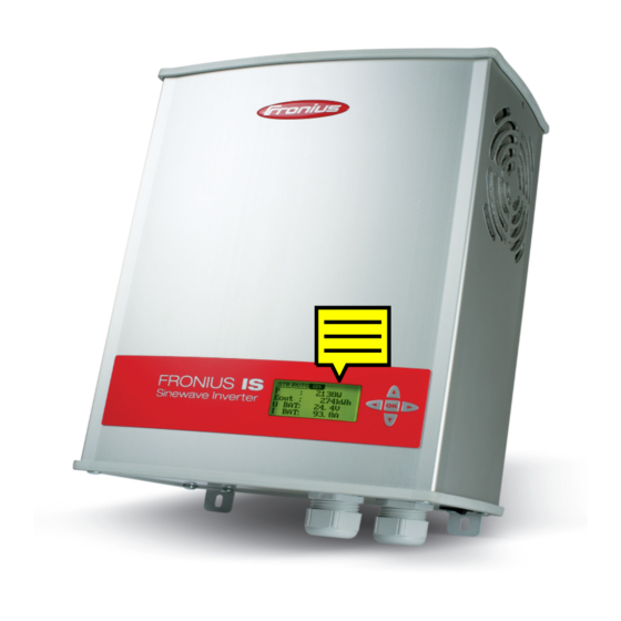
- Page 1 FRONIUS IS 15 / 30 Operating instructions Stand-alone inverter: 42,0426,0048,EN 012007...
- Page 3 Read the manual carefully and you will soon be familiar with all the many great features of your new Fronius product. This really is the best way to get the most out of all the advantages that your machine has to offer.
-
Page 5: Safety Rules
Safety rules DANGER! “DANGER!” indicates an imminently hazardous situation which, if not avoided, will result in death or serious injury. This signal word must be limited to the most extreme situations. This signal word is not used for hazards relating to property damage unless there is also a risk of personal injury appropriate to this level. - Page 6 General Remarks For information about where the safety instructions and warning signs are (continued) located on the machine, please refer to the section of your machine’s in- struction manual headed “General Remarks”. Any malfunctions which might impair machine safety must be remedied immediately before the machine is switched on.
- Page 7 Safety Precauti- Ensure when installing machines with cooling-air vents that the cooling air can flow freely ons at the Machi- through the air vents without obstruction. Only operate the machine with the degree of ne Location protection specified on the rating plate. Information on The inverter generates a maximum sound power level of <80 dB(A) (ref.
- Page 8 Electrical Installa- Electrical installations may only be executed in accordance with the relevant tions national and regional standards and specifications. ESD Protective Danger of damage to electronic components due to electrostatic discharge. Measures Take appropriate protective measures when replacing and installing the components.
-
Page 9: Table Of Contents
General ..............................32 On a regular basis or as required ......................32 Technical data ............................. 33 FRONIUS IS 15 / IS 15 - 48 V ........................ 33 FRONIUS IS 30 / IS 30 - 48 V ........................ 34 Fronius worldwide... -
Page 10: General Remarks
As the user’s electricity needs increase, up to 5 additional inverters per phase can be connected in parallel in 3 phase (maximum) operation, giving a total of 15 FRONIUS IS inverters in a system. The original set-up can be upgraded at any time by installing additional inverters, making the system extremely flexible and future-proof. -
Page 11: Functional Principle
Functional prin- The FRONIUS IS can be operated as a single device or in parallel mode in conjunction ciple with several other devices, depending on the power required. Up to 5 devices may be operated in single-phase mode or up to 15 devices in three-phase mode. -
Page 12: Controls And Connections
Controls and connections General remarks NOTE: As a result of firmware updates, you may find that there are functions available on your device that are not described in these operating instructions or vice versa. Certain illustrations may also differ slightly from the actual cont- rols on your device. -
Page 13: Connections And Main Switch
Connections and main switch (12) (11) (10) Fig. 5 Connections and main switch No. Function (1) AC connection for consumers For connecting AC consumers (2) Strain relief device (3) Switch contact connection For switching external devices (4) Bushing for battery connecting cable (-) terminal (5) Bushing for battery connecting cable (+) terminal (6) Main machine switch (7) Battery cable connection (-) terminal... -
Page 14: Before Commissioning
Before commissioning General remarks WARNING! Operating the equipment incorrectly can cause serious injury and damage. You should not use the functions described until you have thoroughly read and understood the following documents: These operating instructions All the operating instructions for the system components, especially the safety regulations CAUTION! Risk of severe damage if the device is connected to the public mains supply. -
Page 15: Fitting And Connecting The Inverter
Fitting and connecting the inverter General remarks WARNING! An electric shock can be fatal. If the device is connected to the battery during installation, there is a risk of serious injury and damage. The connection compartment should only ever be opened by an authorised electri- cal engineer. -
Page 16: Connecting The Inverter / Starting Up The Consumers
Fitting the inver- ter / Opening the connection compartment (continued) Connecting the Connecting the AC side inverter / Starting Important! Tighten terminals with no more up the consu- than 0.5 Nm torque. mers Connecting the DC side Size 10 NOTE! Risk of damage if the battery cable polarity is reversed. - Page 17 Connecting the Close inverter and finish fitting. inverter / Starting up the consu- mers (continued) Connect inverter to the battery (single operation) Min. ø Min Ah Min. requirement Inverter Max. length Min. ø Min Ah IS 15 2 m (6.56 ft.) 25 mm (.039 in 300 Ah...
- Page 18 Connecting the Start up the consumers inverter / Starting up the consu- mers (continued) Important! For information on connecting and operating several inverters, see the Multi- device operation section.
-
Page 19: Operating Scheme
Operating scheme Symbols used Battery symbol The number indicates the battery charge level Inverter symbol Symbol for the inverter Consumer symbol Symbol for all consumers Messages symbol Symbol for messages that appear during operation Energy flow arrows ON mode: Energy flows from the battery via the inverter to the consumer (continuous operation) AUTO mode: The device checks whether there is a load switched on at regular intervals. -
Page 20: Display
Display The display has 2 visualisation modes: Graphical visualisation Displays the current operating status. Provides a quick over- view of the entire system. Numerical visualisation Displays the most important power values (may be customised in the Setup menu). -
Page 21: Menu Level
Menu level General remarks The system component menu levels are used to make settings for the battery, inverter and consumers. The menu level also contains detailed information about the individual system components. Important! The device may have to be restarted when you confirm the settings. Navigation in the To switch to menu level: menu... - Page 22 Navigation in the Use the navigation buttons to select the required option and then press the OK menu button to access the submenu (continued) Use the navigation buttons to make the required setting in the submenu Change value Move to next position Press the OK button to confirm your settings and exit the submenu To cancel settings: do not press any button for 20 seconds (exits automatically) Hold down for 1 second...
-
Page 23: Selecting The Display Visualisation
Selecting the To select the display visualisation: display visualisa- Press the OK button to access the menu level tion Select the required visualisation using the navigation buttons Press the OK button to confirm the selected visualisation Retrieve mes- When events occur during operation, the device saves them in the form of messages. If sages there is a message available, the Messages symbol appears on the display. -
Page 24: Battery Menu
Battery menu The Battery menu contains information about the battery state and settings. BAT INFO Explanation SOC (State Of Charge) State of charge of the battery Ubat Battery voltage Ibat Battery current Ebat+ Energy drawn from the battery TempB Battery temperature (with battery sensor option only) >... -
Page 25: Inverter Menu
Inverter menu The Inverter menu contains the possible settings for the device options that can be connected, for the display and for single or multi-phase operation. IS INFO Explanation Rel-1 Switching state of relay 1 Rel-2 Switching state of relay 2 Mode Synchronisation settings (single / 1 - 3 phase) Phase... -
Page 26: Consumer Menu
Inverter menu Favourite No. 1 - 4 Displays favourite display values on the numerical display (1 (continued) - 4 = order in which they appear on the display) AC Power Power on the AC side in W AC S Apparent power in VA AC Voltage Voltage on the AC side in V AC kWh Output... - Page 27 Consumer menu To access the Consumer Setup menu: (continued) > Select SETUP and press the OK button LOAD SETUP Explanation Load detect profile Pre-defined load detect profiles Manual Setting as per menu items (factory setting) - Load on limit (ON) - Load hysteresis - Detect pulse - Detect pause...
- Page 28 Consumer menu Detect pulse Number of load detection pulses (n ) in periods (continued) Detect pause Number of load detection pauses (n ) in periods P (W) t (s) E.g.: 50 Hz consumers (period 1/50 s = 20 ms) Detect pulse = 5 -> 5 x 20 ms = 100 ms Detect pause = 50 ->...
-
Page 29: External Connection
External connection General remarks Two relays can be used to switch additional external devices via the inverter. This allows consumers to be switched off automatically, for example, or a signal lamp to light up when the battery has dropped below the minimum voltage set in the Setup menu. WARNING! An electric shock can be fatal. -
Page 30: Configuring The Relay
Connecting Examples for connecting external devices to the relays external devices (continued) Close inverter and connect battery Configuring the Set the switching function for the relay: relay Access the Inverter Setup menu Set the relay: REL-Nr. mode Used to set the function of the selected relay (if SOURCE setting is selected in the Rel No. -
Page 31: Multi-Device Mode
Multi-device mode General remarks If greater power is required, up to 5 inverters can be operated in parallel per phase. In this case, each inverter must be configured individually for its task within the system. Connecting WARNING! Mains voltage can cause fatal injuries. The terminal area must inverters to one only be opened by a qualified electrical installation engineer and must be de- another... -
Page 32: Connecting To Single-Phase Mains Supply
Connecting Connect inverters inverters to one another Important! Note the input and output sockets when connecting the inverters. (continued) IS 1 IS 2 IS 3 Connect first and last inverters together Close inverters Connecting to single-phase mains supply Fig. 6 Wiring diagram for single-phase mains supply, 2 to 5 devices... -
Page 33: Connecting To Three-Phase Mains Supply
Connecting to three-phase mains supply Fig. 7 Wiring diagram for three-phase AC mains supply (e.g. 1 device per phase) Fig. 8 Wiring diagram for three-phase AC mains supply (e.g. 2 devices per phase) In multi-device mode, the battery may be supplied Connecting the Locally: separate battery supply for each inverter battery Local /... -
Page 34: Battery Connection Local / Central
Battery connec- tion local / cen- tral (continued) ø min. min. Ah Fig. 10 Connections for central detection of battery supply (recommended) 3 x ø min. min. Ah Fig. 11 Connections for central detection of battery supply (optional) Min. requirement Inverter Max. -
Page 35: Configuring The Devices
Configuring the NOTE: Risk of damage from consumers that are switched on while the inver- devices ters are being configured. Before configuring the inverters, make sure that the consumers are disconnected all inverters are switched off the described sequence is followed exactly Switch on the inverter to be configured Access the Setup menu for the individual inverter Select SycNo / Phase menu, then set the device number and the phase to be used... -
Page 36: Troubleshooting
Troubleshooting General remarks WARNING! An electric shock can be fatal. Before opening up the machine Move the mains switch to the „O“ position Disconnect the device from the battery Put up an easy-to-understand warning sign to stop anybody inadvertently switching it back on again Using a suitable measuring instrument, check to make sure that electri- cally charged components (e.g. - Page 37 Service codes Error number 191 displayed Display reset (continued) Cause: The display has an internal error which has caused the display to reset itself Remedy: The device will rectify the error itself and the display automatically restart Error number 211 Low battery Cause: Battery voltage is below the set minimum voltage threshold...
- Page 38 Service codes Error number 320 – 323 displayed Internal err (continued) Cause: Device error Remedy: Contact After-Sales Service Error number 331 Internal err Cause: Device error Remedy: Contact After-Sales Service Error number 333 Over current Cause: Short-circuit at AC output Remedy: Disconnect consumer and remedy short-circuit Error number 334...
- Page 39 Service codes Error number 404 displayed No slave (continued) Cause: Error in communication setup in multi-device operation. Remedy: Check the Setup settings and communication links and correct if necessary Error number 405 Internal err Cause: Device error Remedy: Contact After-Sales Service Error number 470 Twin slave Cause:...
-
Page 40: Service, Maintenance And Disposal
Service, maintenance and disposal General The inverter only requires a minimum of service and maintenance under normal opera- ting conditions. However, several items must be followed in order for the inverter to remain operational for years to come. WARNING! An electrical shock can be fatal. Before opening the unit Set power switch to - O - Disconnect unit from battery Attach a clear warning sign against turning the unit on... -
Page 41: Technical Data
Technical data FRONIUS IS 15 / IS 15 IS 15 - 48 V IS 15 - 48 V DC input: Rated voltage 24 V 48 V Voltage range during operation 19 - 30 V 38 - 60 V Max. input voltage... -
Page 42: Fronius Is 30 / Is 30 - 48 V
FRONIUS IS 30 / IS 30 IS 30 - 48 V IS 30 - 48 V DC input: Rated voltage 24 V 48 V Voltage range during operation 19 - 30 V 38 - 60 V Max. input voltage 32 V... -
Page 44: Fronius Worldwide
Fronius USA LLC Solar Electronics Division 4600 Wels-Thalheim, Günter-Fronius-Straße 1, Austria 10421 Citation Drive, Suite 1100, Brighton, MI 48116 E-Mail: pv@fronius.com E-Mail: pv-us@fronius.com http://www.fronius.com http://www.fronius-usa.com Under http://www.fronius.com/addresses you will find all addresses of our sales branches and partner firms! ud_fr_se_so_00913 012007...
Need help?
Do you have a question about the FRONIUS IS 15 and is the answer not in the manual?
Questions and answers