
Related Manuals for Metso E2 Series


Summary of Contents for Metso E2 Series
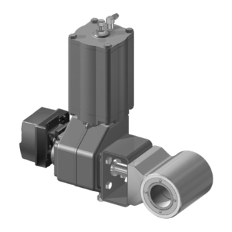
- Page 1 Ceramic Ball Valves Series E2 and E6 Installation, Maintenance and Operating Instructions...
-
Page 2: Table Of Contents
1 E2 70 en Table of Contents GENERAL............3 Valve description........3 Valve markings........3 Technical data........3 CE marking ..........3 Recycling and disposal ......3 Safety precautions ......... 4 TRANSPORTATION, RECEPTION AND STORAGE............4 INSTALLATION AND USE......4 Valve insulation ........ -
Page 3: General
1 E2 70 en GENERAL Technical data Face-to-face length: IEC 534-3-2 / ISA S75.04 Valve description Body pressure rating: ASME Class 300 The E2 ceramic ball valve is a flangeless (wafer type), Max. diff. pressure/ temperature: and E6 is a single flange (lug type) reduced-bore valve specially designed for control of erosive media. -
Page 4: Safety Precautions
EN PN 10, 16, 25, 40 with equipment designed for this purpose or by using ❑ ASME 150, 300 the Metso Nelprof software. Pay attention to work envi- ❑ ISO 7005 PN 20, PN 50 ronment legislation concerning noise emission. - Page 5 1 E2 70 en Lmin. Lmin. Lmin. Lmin. TYPE E2 TYPE E6 Fig. 4 Flange drilling / neck bolting Table 1 Flange drilling / neck bolting, dimensions in mm. ASME 150 / ISO 7005 PN 20. ASME 300 / ISO 7005 PN 50 ASME 150 / ISO 7005 PN 20 ASME 300 / ISO 7005 PN 50 E2_025/E2_01...
-
Page 6: Valve Insulation
1 E2 70 en Table 3 Flange drilling / neck bolting, dimensions in mm. JIS 16 K, 20 K, 30 K JIS 10 K JIS 16 K - 20 K JIS 30 K E2_025/E2_01 E2_040/E2_1H E2_050/E2_02 17.0 17.0 E2_080/E2_03 17.0 20.0 20.0 E2_100/E2_04... - Page 7 1 E2 70 en 4.2.1 Disassembly follows: ❑ base ring CAUTION: ❑ angle rings Do not detach or disassemble a pressurized valve! ❑ saddle ring This warning also applies to individual compo- 5. Place the gasket (16) into the valve body. nents (13).
-
Page 8: Changing The Gland Packing, H-Construction
Torque Thread Tool size requires special tools. It is highly recommended that 25/20, 40/32, 50/40 this work is done by the Metso service organisation. 80/65, 100/80, 150/100, 200 4.6.1 Disassembly Changing the gland packing, 1. Detach the actuator from the valve, see Section H-construction 4.7.1. -
Page 9: Detaching And Installing The Actuator
1 E2 70 en Table 8 Tightening torques of insert 4.7.2 Installation onto the valve Clean the shaft boring of the actuator. Lubricate the Nominal size Max. torque Thread Tool Nm * shaft boring and the valve shaft with, for example, 25/20 M52 x 1,5 C279922... -
Page 10: Malfunction
1 E2 70 en MALFUNCTION Table 9 shows malfunctions that might appear after pro- longed use. Table 9 Malfunctions Symptom Possible fault Recommended action Valve can not be opened/closed Impurities on the ball surface Clean the ball surface mechanically through the flow ports Leakage at the base of the shaft Gland packing leaks Check tightening of the strain ring/gland. -
Page 11: Exploded Views And Parts List
1 E2 70 en EXPLODED VIEWS AND PARTS LIST A-construction H-construction Item Description Spare part category Body Ball Bushing Shaft Bracket Insert Axial bearing Bearing Strain ring Gland bushing V-ring set Spring (A-construction only) Hexagon screw Sheet ring Sheet ring (A-construction only) Gasket O-ring (A-construction only) Lock ring... -
Page 12: Dimensions And Weights
1 E2 70 en DIMENSIONS AND WEIGHTS Key acc. to ANSI B17.1 Key acc. to ANSI B17.1 Dimensions of Dimensions of mounting level acc. to mounting level acc. to ISO 5211 ISO 5211 øB øB E2 DN25-100 E6 DN25-200 Valve is in open position Valve is in open position Dimensions, mm Weight, kg... - Page 13 1 E2 70 en NPT *) **) MOUNTING POSITION A (STANDARD) MOUNTING POSITION B NPT *) **) ØD ØD NPT *) NPT *) NPT ***) NPT ***) SUPPLY 1/4 NPT ØB SUPPLY 1/4 NPT SIGNAL PG 11 SIGNAL PG 11 ØB Dimensions, mm Dimensions, mm...
- Page 14 1 E2 70 en NPT *) **) MOUNTING POSITION A (ST A NDARD) MOUNTING POSITION B NPT *) **) ØD ØD NPT *) NPT *) NPT ***) NPT ***) SUPPL Y 1/4 NP T SUPPL Y 1/4 NP T ØB SIGNAL PG 11 SIGNAL PG 11 ØB...
-
Page 15: Type Code
1 E2 70 en TYPE CODE CERAMIC BALL VALVE, series E2 CV-VALUE OF THE VALVE DN 25 SIZE Standard, without sign ASME EN and JIS C05- Maximum C 1" 25 mm C15- Maximum C 1 1/2" 40 mm 2" 50 mm 3"... - Page 16 1 E2 70 en Metso Automation Inc. Europe, Vanha Porvoontie 229, P.O. Box 304, FI-01301 Vantaa, Finland. Tel. +358 20 483 150. Fax +358 20 483 151 North America, 44 Bowditch Drive, P.O. Box 8044, Shrewsbury, MA 01545, USA. Tel. +1 508 852 0200. Fax +1 508 852 8172 South America, Av.
Need help?
Do you have a question about the E2 Series and is the answer not in the manual?
Questions and answers