
Related Manuals for McQuay ALR 110F


Summary of Contents for McQuay ALR 110F
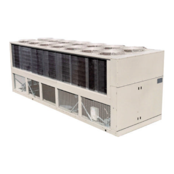
- Page 1 Product Manual PM ALR2-3 Group: Chiller Date: August 2000 Supersedes: PM ALR2-2 Air-Cooled Reciprocating Water Chillers ALR 110F through 150F 110 to 150 Tons, 380 to 525 kW R-22 60 Hertz © 2000 McQuay International...
-
Page 2: Table Of Contents
"McQuay" is a registered trademark of McQuay International © 1997 McQuay International "Information covers McQuay International products at the time of publication and we reserve the right to make changes in design and construction at anytime without notice" ALR 110F – 150F... -
Page 3: Introduction
Introduction McQuay International offers a complete line of air-cooled chillers from 10 to 425 tons (35 to 1500 kW) utilizing scroll, reciprocating, and rotary screw compressors. The McQuay ALR reciprocating compressor, air-cooled chiller is a product of the McQuay commitment to offer reliable, energy efficient equipment design. -
Page 4: Design Advantages
Design Advantages Construction The ALR 110F through 150F are factory assembled and mounted on a rugged steel channel base. The channel base distributes the unit weight for low roof loading. Lifting holes in the base simplify rigging. Optional wire mesh base guards are available to prevent intrusion to the area under the coils. - Page 5 Outside air temperature sensor is standard. Reset options are; outside air, return water, remote reset, demand limit, zone temperature reset. The optional Zone Terminal and Display control is required to adjust the reset setpoints. Product Manual ALR2-3 ALR 110F – 150F...
- Page 6 Adjusting allows adjustment of any flashing set points, three at a time, typically set up so that the relationship between values can be viewed simultaneously. For example: • Display 1 = Lvg Water temp, Display 2 = Lvg Water SP, Display 3 = % Unit Load ALR 110F – 150F Product Manual ALR2-3...
- Page 7 AGZ-AGR Optional MicroTech Control The exclusive MicroTech microprocessor control is common throughout McQuay equipment. The interface is a 12 key keypad and 2-line, 32 character backlit liquid crystal display. The MicroTech continuously performs self-diagnostic checks on all system temperatures, pressures, and safeties, and will automatically shut down a circuit or the entire unit if a fault condition occurs.
- Page 8 Figure 3, Optional MicroTech Control Panel Figure 4, MicroTech Control ALR 110F – 150F Product Manual ALR2-3...
-
Page 9: Selection Procedure
264 gpm, 54°F - 44°F chilled water 0.0001 evaporator fouling factor From Performance Table 4, an ALR 110F at the given conditions will produce 110.9 tons with a compressor kW input of 120.6 and a unit EER of 9.8 Use the following formula (for water) to calculate missing elements: ×... -
Page 10: Performance Adjustment Factors
Foreign matter in the chilled water system will adversely affect the heat transfer capability of the evaporator, and could increase the pressure drop and reduce the water flow. To ensure optimum unit operation, proper water treatment must be maintained. ALR 110F – 150F Product Manual ALR2-3... - Page 11 1.034 0.956 1.032 0.934 1.024 0.893 1.011 0.968 1.036 0.961 1.034 0.939 1.026 0.897 1.013 0.972 1.037 0.965 1.035 0.943 1.027 0.901 1.014 NOTE: Contact McQuay sales office for applications above 6,000 feet. Product Manual ALR2-3 ALR 110F – 150F...
-
Page 12: Performance Data
For 208V units multiply capacity and EER by 0.98. For units with SpeedTrol option multiply capacity and EER by 0.99. Interpolation is allowed; extrapolation is not permitted. Consult McQuay for performance outside the cataloged ratings. kWi input is for compressors only. EER is for the entire unit, including compressors, fan motors and control power. - Page 13 For units with SpeedTrol option multiply capacity and COP by 0.99. Interpolation is allowed; extrapolation is not permitted. Consult McQuay for performance outside the cataloged ratings. kWi input is for compressors only. COP is for the entire unit, including compressors, fan motors and control power.
-
Page 14: Part Load Data
143.2 178.2 145F 75.00 107.5 104.4 12.4 13.5 50.00 71.6 61.3 14.0 25.00 35.9 27.7 15.5 100.00 149.5 186.0 150F 75.00 112.1 109.4 12.3 13.4 50.00 74.7 64.4 13.9 25.00 37.4 29.4 15.3 ALR 110F – 150F Product Manual ALR2-3... -
Page 15: Pressure Drops
37.5 (111.8) 200 (12.6) 5.3 (15.8) 535 (33.8) 40.0 (119.2) 205 (13.0) 5.8 (17.3) 550 (34.7) 42.0 (125.2) 215 (13.6) 4.3 (12.8) 570 (36.0) 29.5 (87.9) 220 (13.9) 4.5 (13.4) 590 (37.2) 31.0 (92.4) Product Manual ALR2-3 ALR 110F – 150F... -
Page 16: Sound Data
Sound levels can be as important as unit cost and efficiency, and must be addressed before the start of any development program. Efforts by McQuay Design Engineers to design chillers that are sensitive to the sound requirements of the market have paid off. - Page 17 30.0 27.1 24.0 50 (15) 34.5 31.6 28.5 75 (23) 38.0 35.1 32.0 100 (30) 40.5 37.6 34.5 150 (46) 44.0 41.1 38.0 200 (61) 46.5 43.6 40.5 300 (91) 50.0 47.6 44.0 Product Manual ALR2-3 ALR 110F – 150F...
- Page 18 3 dB proportionally from 95°F to 65°F. For example, at 95°F the sound pressure is per Error! Reference source not found., at 85°F one dB can be subtracted, at 75°F two dB can be subtracted, and so on for any temperature between 65°F and 95°F. ALR 110F – 150F Product Manual ALR2-3...
- Page 19 3 to 6 dB (one or three sided wall). Note: The effect of adjacent walls on air recirculation and restriction must always be considered when employing sound barrier walls. Product Manual ALR2-3 ALR 110F – 150F...
-
Page 20: Electrical Data
Electrical Data Table 10, ALR 110F - 150F, Electrical Data, Single Point Fuse or HACR Breaker Size Min. Circuit Field Wire (Conduit Connection) Unit Volts Ampacity Recommended Maximum Size (MCA) Quantity Wire Gauge Quantity Size 4.00 (102) 4.00 (102) 110F 2.50 (64) - Page 21 Table 11, ALR 110F - 150F, Electrical Data, Multiple Point Power Supply Field Power Supply Field Power Supply Field Min. Fans and Controls Fusing(1) Circuit #1 Fusing (1) Circuit #2 Fusing (1) Min. Min. Ckt. Field Wire Field Wire Field Wire...
- Page 22 Table 12, ALR 110F -150F, Compressor and Condenser Fan Motor Amp Draw Rated Load Amps Locked Rotor Amps Compressors Compressors Unit Volts Motors Motors Across-The-Line Reduced Inrush Size Motor (Each) (Each) No. 1 No. 2 No. 3 No. 4 No. 1 No. 2 No. 3 No. 4 23.7...
- Page 23 Table 13, ALR 110F - 150F, Field Wiring Data, Single Point Power Wiring to Wiring to Optional Factory Mounted Standard Power Block Disconnect Switch Unit Volts Terminal Connector Wire Range/Phase Terminal Connector Wire Range/Phase Size Amps (Copper Wire Only) Amps (Copper Wire Only) (2 qty.) 1/0 - 600 MCM...
- Page 24 Table 14, ALR 110F through 150F, Field Wiring Data, Multiple Point Power Wiring to Standard Power Block Unit Volts Terminal Amps Connector Wire Range Per Phase (Copper Wire Only) Size Circuit 1 Circuit 2 Circuit 3 Circuit 1 (Fans) Circuit 2 Circuit 3 (1 qty.) #12 - 2/0...
- Page 25 Multiple point power supply requires three independent power circuits, each with separate disconnect. All field wiring to unit power block or optional non-fused disconnect switch must be copper. All field wire size values given in table apply to 75°C rated wire per NEC. Product Manual ALR2-3 ALR 110F – 150F...
- Page 26 Figure 9, ALR 110F through 150F, Typical Field Wiring Diagram UNI T MAIN OPTIONAL DISCONNECT TERM I NAL BLOC K 3 PHASE TOC OMP RESSOR(S) P OW ER AND FAN MOTORS. SUP PLY STANDARD FUSED CONTROL CIRCUIT TRANSFORMER SEE NOTE A...
-
Page 27: Physical Data
Physical Data Table 15, Physical Data ALR 110F through 135F ALR MODEL NUMBER PHYSICAL DATA 110F 120F 130F 135F BASIC DATA Ckt.1 Ckt.2 Ckt.1 Ckt.2 Ckt.1 Ckt.2 Ckt.1 Ckt.2 Unit Capacity @ ARI Conditions, Tons (kW) (1) 110.9 (388.1) 122.2 (427.7) 129.6 (453.6) - Page 28 Drain - NPT int, In. (mm) .5 (12.7) .5 (12.7) .5 (12.7) Vent - NPT int, In. (mm) .5 (12.7) .5 (12.7) .5 (12.7) NOTES: Nominal capacity based on R-22, 95°F ambient air and 54°F/44°F water range. ALR 110F – 150F Product Manual ALR2-3...
-
Page 29: Dimensional Data
99.0 (2515) 41.7 (1059) 36.0 (914) 102 (2591) 192 (4877) 150F NOTE: Only left hand evaporator connections (as shown) are available. Discharge NOTE: Add 22 in. (559 mm) to each side for hail guards. Product Manual ALR2-3 ALR 110F – 150F... -
Page 30: Installation And Application
Give special consideration to low ambient operation where snow can accumulate. Keep condenser coils and fan discharge free of snow or other obstructions to permit adequate airflow for proper unit operation. ALR 110F – 150F Product Manual ALR2-3... - Page 31 Inevitably there are situations where these clearances cannot be maintained due to site restrictions such as units being too close together or a fence or wall restricting airflow, or both. Fortunately the McQuay ALR chillers have several features that mitigate the penalties attributed to restricted airflow.
- Page 32 The worst case is to have wind blowing hot discharge air into the wall. Figure 13, Unit Adjacent to Wall Figure 14, Adjustment Factors ALR 110F – 150F Product Manual ALR2-3...
- Page 33 Pit or solid wall surrounds should not be used where the ambient air temperature exceeds 105°F (40°C). Figure 15, Two Units Side by Side Figure 16, Adjustment Factor (1.8) (2.4) (3.0) (3.6) (1.8) (2.4) (3.0) (3.6) Product Manual ALR2-3 ALR 110F – 150F...
- Page 34 Their adjustment factors will be the same as Case 2. All inside units (only number 2 in this case) are influenced on both sides and must be adjusted by the factors shown below. Figure 17, Three or More Units Figure 18, Adjustment Factor ALR 110F – 150F Product Manual ALR2-3...
- Page 35 8 feet (2.4 meters) from the unit. For example, do not average 4 feet and 20 feet to equal 12 feet. Figure 19, Open Screening Walls Figure 20, Wall Free Area vs. Distance Product Manual ALR2-3 ALR 110F – 150F...
- Page 36 Steel grating is sometimes used to cover a pit for safety considerations. The grating material must provide abundant open area or serious recirculation problems will occur. It would be prudent to have any pit installation reviewed by McQuay application engineers prior to installation. Figure 21, Pit Installation Figure 22, Adjustment Factor ALR 110F –...
- Page 37 Chilled Water Piping On ALR 110F through 150F the thermostat sensor is factory mounted in the leaving water well. If an optional high return water sensor is provided, install sensor bulb in a field supplied tee or strap to the outside of the water line.
-
Page 38: System Water Volume
Variable water flow involves changing the water flow through the evaporator as the load changes. McQuay chillers are designed for this duty provided that the rate of change in water flow is slow and the minimum & maximum flow rates for the vessel are not exceeded. - Page 39 The correct choice of fin material or selection of a coating can have a dramatic effect on the life and efficiency of the coil when corrosive or abrasive material is present. McQuay offers a variety of coil options to satisfy most ambient conditions.
-
Page 40: Remote Evaporator
These derates are based on a suction line pressure drop equivalent of approximately 2°F (1°C) change in saturation temperature. For R-22 applications: Capacity = Tons (kW) x 0.97 Power = Compressor kW x 0.99 ALR 110F – 150F Product Manual ALR2-3... -
Page 41: Line Sizing
1 5/8 2 5/8 1 1/8 3 1/8 1 5/8 2 5/8 1 1/8 3 1/8 1 5/8 2 5/8 1 1/8 3 1/8 1 5/8 2 5/8 1 1/8 3 1/8 1 5/8 Product Manual ALR2-3 ALR 110F – 150F... -
Page 42: Dimensions, Remote Evaporator
11.0 (279) 5 (152) 120-140 95.5 (2426) 20.4 (518) 14.0 (356) 84.0 (2134) 6.8 (173) 12.0 (305) 8 (203) 145-150 96.8 (2459) 21.4 (544) 16.0 (406) 84.6 (2149) 6.9 (175) 12.8 (325) 8 (203) ALR 110F – 150F Product Manual ALR2-3... -
Page 43: Optional Features
Part winding start is standard on 208V and 230V units and optional on 380V, 460V and 575V. It works in conjunction with the unit's standard compressor sequence start timers to reduce current inrush by providing two-step start of each compressor. This feature is not normally required on the McQuay multiple compressor, sequence start design. -
Page 44: Vibration Isolators
Dual Setpoint Control (Ice Storage Applications) Unit sizes ALR 110F-150F must be equipped with the optional MicroTech controls for ice duty applications. MicroTech Controller A complete factory installed microprocessor controller as described elsewhere in this manual. Zone Terminal For use with the standard UNT controller. It can be factory mounted on the unit or located remotely. -
Page 45: Specifications
Specifications NOTE: Specifications are available on disk from the local McQuay Representative SECTION 15XXX AIR-COOLED RECIPROCATING CHILLERS ALR 110F-ALR 150F PART 1 - GENERAL 1.01 SUMMARY Section includes design, performance criteria, refrigerants, controls, and installation requirements for air-cooled reciprocating compressor packaged chillers. - Page 46 Performance: Refer to the schedule of performance on the drawings. The chiller shall be capable of stable operation to a minimum of 17 percent of full load without hot gas bypass. Performance shall be in accordance with applicable ARI Standard. ALR 110F – 150F Product Manual ALR2-3...
- Page 47 Refrigerant Circuit: Each refrigerant circuit shall include a liquid line shutoff valve, refrigerant filter-drier, sight glass with moisture indicator, liquid line solenoid valve (no exceptions), thermal expansion valve, discharge gas muffler, insulated suction line and a 450 psig (3104 kPa) relief valve. Product Manual ALR2-3 ALR 110F – 150F...
- Page 48 The LCD type display shall have a minimum of 32 characters with all messages in plain English. Coded messages and LED displays are not acceptable. Critical parameters shall have their own section of control and be password protected. ALR 110F – 150F Product Manual ALR2-3...
- Page 49 Chilled water flow switch to be field mounted in the chilled water line by the contractor and field wired to terminals in the control panel. • Spring vibration isolators for field installation • Disconnect switch with through-the-door handle Product Manual ALR2-3 ALR 110F – 150F...
- Page 50 Provide all appurtenances required to insure a fully operational and functional chiller. 3.02 START-UP Ensure proper charge of refrigerant and oil. Provide testing, and starting of machine, and instruct the Owner in its proper operation and maintenance. ALR 110F – 150F Product Manual ALR2-3...
- Page 52 Post Office Box 2510 Staunton, Virginia 24402-2510 USA • 800-432-1342 • www.mcquay.com...
Need help?
Do you have a question about the ALR 110F and is the answer not in the manual?
Questions and answers