Table of Contents
Advertisement
Advertisement
Table of Contents
Troubleshooting

Related Manuals for Vertiv Liebert GXT3 Series


Summary of Contents for Vertiv Liebert GXT3 Series
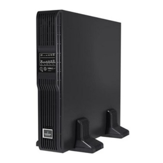
- Page 1 Liebert® GXT3™ 208V, 5000-10,000VA, 6000RTL630 Installer/User Guide...
- Page 2 Technical Support Site If you encounter any installation or operational issues with your product, check the pertinent section of this manual to see if the issue can be resolved by following outlined procedures. Visit https://www.VertivCo.com/en-us/support/ for additional assistance.
-
Page 3: Table Of Contents
8.2 Initial Startup and Electrical Checks 8.3 Manual Battery Test 8.4 Put the Liebert GXT3 in Manual Bypass 8.5 Shut Down the Liebert GXT3 8.6 Disconnecting Input Power from the Liebert GXT3 8.7 Maintenance Bypass 9 Communication Vertiv | Liebert® GXT3 ™ Installer/User Guide |... - Page 4 10.5 Checking UPS Functions 10.6 Replacing the Power Module on 8000 and 10,000VA models 11 Troubleshooting 11.1 UPS Symptoms 11.1.1 Indicators 11.1.2 Audible Alarm 11.2 Troubleshooting 12 Specifications 12.1 Auto-Learning Battery Run Times Vertiv | Liebert® GXT3 ™ Installer/User Guide |...
-
Page 5: Important Safety Instructions
• Do not lay tools or other metal objects on the batteries. • If the battery kit is damaged in any way or shows signs of leakage, contact your local Vertiv representative immediately. • Do not dispose of batteries in a fire. The batteries may explode. - Page 6 Storing magnetic media on top of the UPS may result in data loss or corruption. Turn Off and isolate the UPS before cleaning it. Use only a soft cloth, never liquid or aerosol cleaners. Vertiv | Liebert® GXT3 ™ Installer/User Guide |...
-
Page 7: Glossary Of Symbols
Indicates caution followed by important instructions AC input AC output Requests the user to consult the manual Indicates the unit contains a valve-regulated lead acid battery Recycle DC voltage Equipment grounding conductor Bonded to ground Vertiv | Liebert® GXT3 ™ Installer/User Guide |... - Page 8 AC voltage ON/Alarm Silence/Manual Battery Test OFF/Bypass WEEE Vertiv | Liebert® GXT3 ™ Installer/User Guide |...
-
Page 9: Introduction
This port provides detailed operating information including voltages, currents and alarm status to the ® host system when used in conjunction with Liebert MultiLink . Liebert MultiLink can also remotely control UPS operation. Vertiv | Liebert® GXT3 ™ Installer/User Guide |... -
Page 10: System Description
The DC-to-DC converter utilizes energy from the battery system and raises the DC voltage to the optimum operating voltage for the inverter. This allows the inverter to operate continuously at its optimum efficiency and voltage, thus increasing reliability. Vertiv | Liebert® GXT3 ™ Installer/User Guide |... -
Page 11: Battery
Standby/Manual Bypass button once and hold it for about 2 seconds. NOTE: The bypass power path does NOT protect the connected equipment from disturbances in the utility supply. Vertiv | Liebert® GXT3 ™ Installer/User Guide |... - Page 12 This page intentionally left blank. Vertiv | Liebert® GXT3 ™ Installer/User Guide |...
-
Page 13: Major Components
(see Figure 3.5 on page 16). Figure 3.1 Liebert GXT3 front view—rack-mount and tower configurations Table 3.1 GXT3 Front View Description ITEM DESCRIPTION Upper Bezel Status Indicators and Controls Lower Bezel and Battery Access Door Vertiv | Liebert® GXT3 ™ Installer/User Guide |... - Page 14 NOTE: Hardwire and hardwire/receptacle boxes that include a manual bypass switch permit AC power to continue to flow from the utility input to the load while the box is removed from the UPS. For details, refer to Removable Power Distribution Box on page 16. Vertiv | Liebert® GXT3 ™ Installer/User Guide |...
- Page 15 Output Breaker for L6-20R #2 and #3 Output Breaker for L6-30R #4 Output Breaker for L6-30R #5 External Battery Connector IT Power System Access Cover Input Breaker for L6-30P #1 Maintenance Bypass Breaker Vertiv | Liebert® GXT3 ™ Installer/User Guide |...
-
Page 16: Removable Power Distribution Box
External Battery Connector Cover for Power Distribution Box Connections 3.2 Removable Power Distribution Box The UPS is shipped with a power distribution pack installed. This box contains the UPS input circuit breaker. Vertiv | Liebert® GXT3 ™ Installer/User Guide |... - Page 17 PD2-001 Receptacles: four 5-20; one L14-30; one L6-30R L14-30 Input Power Connector Input Power Breaker Maintenance Bypass Breaker Output Power Breakers for Pigtails Push Button Output Power Breakers for Two L5-20 Receptacles (second push button breaker obscured) Vertiv | Liebert® GXT3 ™ Installer/User Guide |...
- Page 18 PD2-104 Receptacles: four 5-20R two L6-30R two L6-20R PD2-105 Receptacles: four 5-20R two L5-30R two L5-20R PD2-106 Receptacles: four L6-20R four L5-20R Similar features on other distribution boxes arranged differently 5-20R Output Receptacles Vertiv | Liebert® GXT3 ™ Installer/User Guide |...
-
Page 19: Internal Battery Packs
Table 3.8 Internal Battery Pack Feature Descriptions ITEM DESCRIPTION Front of Battery Pack Battery Connector Battery Handles NOTE: Liebert GXT3 8000 and 10,000VA battery packs shown; 5000 and 6000VA battery packs have same features. Vertiv | Liebert® GXT3 ™ Installer/User Guide |... - Page 20 This page intentionally left blank. Vertiv | Liebert® GXT3 ™ Installer/User Guide |...
-
Page 21: What's Included
NOTE: The Liebert GXT3 External Battery Cabinet shipping package includes one battery cabinet, two spacers for the 5000 and 6000VA models and four spacers for the 8000 and 10000VA models for tower configuration and one DC power cable. Vertiv | Liebert® GXT3 ™ Installer/User Guide |... - Page 22 This page intentionally left blank. Vertiv | Liebert® GXT3 ™ Installer/User Guide |...
-
Page 23: Installation And Configuration
4. Adjust the direction of the operation and display panel and logo on the Liebert GXT3. a. Remove the front plastic bezel cover as shown in Figure 5.2 on the next page. Vertiv | Liebert® GXT3 ™ Installer/User Guide |... - Page 24 Pull the operation and display panel gently, rotate it 90 degrees clockwise and snap it back into position, as shown in Figure 5.3 below. Figure 5.3 Rotate the operation and display panel Table 5.3 Rotation Description ITEM DESCRIPTION Operation and Display Panel Rotated Clockwise 90 Degrees Vertiv | Liebert® GXT3 ™ Installer/User Guide |...
-
Page 25: Rack-Mount Ups Installation
2. Determine the height position inside the rack enclosure where you want to mount the UPS or battery cabinet. CAUTION: Reduce the risk of tipping the rack enclosure by placing the UPS or battery cabinet in the lowest possible rack position. Vertiv | Liebert® GXT3 ™ Installer/User Guide |... - Page 26 Fasten the rear member and the front member together using four screws and four nuts per bracket assembly as shown in at right. For maximum support, insert fasteners for each bracket assembly as Vertiv | Liebert® GXT3 ™ Installer/User Guide |...
- Page 27 Table 5.4 Installation Rack Mount Bracket Descriptions ITEM DESCRIPTION UPS or battery cabinet Apply Grease Apply Grease (inside) Insert the UPS into the front members, lift the front and push it into the rack. Vertiv | Liebert® GXT3 ™ Installer/User Guide |...
-
Page 28: External Battery Cabinet Installation
Second connector permits adding more battery cabinets to 6000 Cable connects battery cabinet to 6000VA Liebert GXT3 Inspect the external battery cabinet for freight damage. Report damage to the carrier and your local dealer or Emerson representative. Vertiv | Liebert® GXT3 ™ Installer/User Guide |... -
Page 29: Connect Input/Output Power
6. Remove the power distribution box from the UPS and set it aside. 7. Loosen the screws over the plastic cover for the connector on the rear of the panel. 8. Slide the plastic cover over the connector and tighten the screws. Vertiv | Liebert® GXT3 ™ Installer/User Guide |... -
Page 30: Remove The Power Distribution Cover From 8000 And 10,000Va Models
6. Remove the cover or power distribution box from the UPS and set it aside. 7. If removing a power distribution box, carefully pull apart the power distribution box connector and the UPS connector. Vertiv | Liebert® GXT3 ™ Installer/User Guide |... -
Page 31: Install The Power Distribution Box On 5000 And 6000Va Models
Electrical connections are made through a removable power distribution box that attaches to the rear of the UPS. • PD2-HDWR, PD2-HDWR-MBS, PD2-001, PD2-002, PD2-003, PD2-004, PD2-005 and PD2-006 models fit the 5000 and 6000VA models of the Liebert GXT3 • PD2-L630 fits the GXT3-6000RTL630 Vertiv | Liebert® GXT3 ™ Installer/User Guide |... - Page 32 (MAXIMUM) EXTERNAL (INCLUDING GROUND WIRE) ACCEPTED BY TIGHTENING OVERCURRENT PROTECTION (75°C COPPER WIRE) TERMINAL BLOCK TORQUE GXT3-5000RT208 10AWG (4mm 8AWG (6mm GXT3-6000RT208 20 in-lb GXT3-6000RTL630 (2.26 Nm) GXT3-8000RT208 6AWG (10mm 4AWG (16mm GXT3-10000RT208 Vertiv | Liebert® GXT3 ™ Installer/User Guide |...
-
Page 33: It Power System Configuration-Liebert Gxt3-6000Rtl630 Only
2. Disconnect the connectors as shown in figure. 3. Reinstall IT Power System Access Cover and screws. Figure 5.11 Remove cover from IT Power System Connectors compartment Table 5.10 Compartment Descriptions ITEM DESCRIPTION Remove Screws IT Power System Connectors Vertiv | Liebert® GXT3 ™ Installer/User Guide |... - Page 34 This page intentionally left blank. Vertiv | Liebert® GXT3 ™ Installer/User Guide |...
-
Page 35: Configuration Program
In addition to the Liebert GXT3 UPS, you will need the configuration program CD and USB cable included in the UPS ® ® accessory box. A Microsoft Windows 95 or later computer, desktop or laptop, is also required to set up and run the configuration program. Vertiv | Liebert® GXT3 ™ Installer/User Guide |... - Page 36 This page intentionally left blank. Vertiv | Liebert® GXT3 ™ Installer/User Guide |...
-
Page 37: Controls And Indicators
25% increments (±5%). The load level indicator will illuminate as shown in Figure 7.2 on the next page. The load level indicators display the approximate electrical load placed upon the UPS at all times. Vertiv | Liebert® GXT3 ™ Installer/User Guide |... -
Page 38: Battery Level Indicators (5 Green)
7.5 UPS Status Indicators UPS status is indicated by five symbols: fault indicator, AC input indicator, battery indicator, inverter indicator and bypass indicator. Table 7.1 on the facing page shows the symbols and their meanings. Vertiv | Liebert® GXT3 ™ Installer/User Guide |... - Page 39 On when the inverter is supplying power; Off when the inverter is not supplying power On when the bypass is supplying power; Off when the bypass is not supplying power; Bypass Indicator Amber flashing when utility power is outside specifications Vertiv | Liebert® GXT3 ™ Installer/User Guide |...
- Page 40 This page intentionally left blank. Vertiv | Liebert® GXT3 ™ Installer/User Guide |...
-
Page 41: Operation
UPS to recharge the batteries for 1 hour, then initiate a manual battery test again. • If none of the five Battery LEDs illuminate during the second manual battery test, replace batteries and contact your local Emerson representative or Emerson Channel Support. Vertiv | Liebert® GXT3 ™ Installer/User Guide |... -
Page 42: Put The Liebert Gxt3 In Manual Bypass
2. Move the Manual Bypass breaker on the rear of the UPS to the bypass position. This requires loosening the captive screw and sliding the bracket up and away from the Manual Bypass breaker. Vertiv | Liebert® GXT3 ™ Installer/User Guide |... -
Page 43: Communication
Remote Battery Mode Shutdown can be performed using a switch connected to the pins in Set 4 and mounted at remote location. Activation of the Battery Mode Shutdown will be logged as an event in the event history log. Vertiv | Liebert® GXT3 ™ Installer/User Guide |... -
Page 44: On Battery
The Liebert IntelliSlot MultiPort 4 Card allows installing Liebert MultiLink software on four computers and coordinate shutdown in the event of a power failure. The Liebert IntelliSlot Relay Card provides dry contact relay outputs for custom wired applications and delivers support for built-in shutdown for AS/400 systems. Vertiv | Liebert® GXT3 ™ Installer/User Guide |... -
Page 45: Remote Emergency Power Off
UPS ships with REPO jumper installed allowing the UPS to operate Note: Normally closed switch system (fail-safe) Opening the REPO connection will disable the UPS. Manual restart using the front panel is required after the REPO connection is closed again. Vertiv | Liebert® GXT3 ™ Installer/User Guide |... - Page 46 This page intentionally left blank. Vertiv | Liebert® GXT3 ™ Installer/User Guide |...
-
Page 47: Maintenance
NOTE: 8000VA/ 10,000VA model shown; 5000VA & 6000VA model arrangements is the same except smaller 4. Gently pull the battery wires out and disconnect the battery plugs and battery receptacles, as shown in Figure 10.2 on the next page. Vertiv | Liebert® GXT3 ™ Installer/User Guide |... - Page 48 5. Grasp the battery handle and pull one of the internal battery packs out of the UPS, as shown in Figure 10.3 on the facing page. Repeat this step if both battery packs will be replaced. Each model has two battery packs Vertiv | Liebert® GXT3 ™ Installer/User Guide |...
-
Page 49: Battery Charging
If the Liebert GXT3 will be stored for a long time, Emerson recommends connecting the UPS to input power for at least 24 hours every four to six months to ensure full recharge of the batteries. Vertiv | Liebert® GXT3 ™ Installer/User Guide |... -
Page 50: Precautions
3. Open the input circuit breaker on the rear of the UPS (see Figure 3.7 on page 18). 4. Open the output circuit breaker on the rear of the UPS (see Figure 3.7 on page 18). 5. Remove the top two front plastic bezels by pulling them forward. Vertiv | Liebert® GXT3 ™ Installer/User Guide |... - Page 51 21. Press the On button on the front panel one time to return the UPS to Normal Mode operation (see Figure 7.1 on page 37). NOTE: The power module restraint lever must be fully engaged for the UPS to operate in Normal Mode. Vertiv | Liebert® GXT3 ™ Installer/User Guide |...
- Page 52 This page intentionally left blank. Vertiv | Liebert® GXT3 ™ Installer/User Guide |...
-
Page 53: Troubleshooting
REPO (one quarter-second beep at quarter-second intervals) B&E Short circuit on the output ® C&E UPS shutdown by command from communication (USB port or Liebert IntelliSlot port) (no audible) Utility LED flash L-N reverse Vertiv | Liebert® GXT3 ™ Installer/User Guide |... -
Page 54: Audible Alarm
Ensure utility supply voltage is within acceptable limits for UPS. Keep UPS plugged in continuously at least 24 hours to recharge UPS has reduced battery backup time Batteries are not fully charged batteries. Vertiv | Liebert® GXT3 ™ Installer/User Guide |... - Page 55 When reporting a UPS issue to Emerson, include the UPS model and serial number. These are on the top panel of the Liebert GXT3. Vertiv | Liebert® GXT3 ™ Installer/User Guide |...
- Page 56 This page intentionally left blank. Vertiv | Liebert® GXT3 ™ Installer/User Guide |...
-
Page 57: Specifications
User Configurable L1-N, L2-N VAC 100/110/115/120VAC, ±2% L1-N, L2-N, Operating Load Range 105% to 130% 1 Minute 131% to 150% 10 seconds 151% to 200% 1 second >200% (impact load) At least 5 cycles Vertiv | Liebert® GXT3 ™ Installer/User Guide |... - Page 58 20.9 x 29.3 x 14.8 (530 x 745 x 377) Weight, lb (kg) Unit 51.8 (23.5) Shipping 66.1 (30) Input AC Parameters Nominal Operating Frequency Factory Default VAC 208/220/230/240VAC User Configurable VAC (may be modified with configuration program) Vertiv | Liebert® GXT3 ™ Installer/User Guide |...
- Page 59 Less than 50dBA at 3.2ft. (1m) front and sides Agency Safety UL 1778, c-UL Listed EMI/EMC FCC Class A EN61000-4-2 Radiated Susceptibility EN61000-4-3 Electrical Fast Transient EN61000-4-4 Surge Immunity EN61000-4-5 Transportation ISTA Procedure 1A Vertiv | Liebert® GXT3 ™ Installer/User Guide |...
- Page 60 Relative Humidity Up to 10,000 ft. (3000m) at 77°F (25°C) without derating Operating Elevation Agency Safety UL 1778, c-UL Listed RFI/EMI FCC Part 15, Subpart B, Class A Transportation ISTA Procedure 1A Vertiv | Liebert® GXT3 ™ Installer/User Guide |...
- Page 61 Relative Humidity Up to 10,000 ft. (3000m) at 77°F (25°C) without derating Operating Elevation Agency UL 1778, c-UL Listed Safety FCC Part 15, Subpart B, Class A RFI/EMI ISTA Procedure 1A Transportation Vertiv | Liebert® GXT3 ™ Installer/User Guide |...
- Page 62 (302 x 522 x (302 x 522 x (302 x 522 x 220) 220) 220) 220) 220) 220) Weight, lb (kg) 4.4 (2) 6.6 (3) 6.6 (3) 6.6 (3) 4.4 (2) 6.6 (3) Unit Vertiv | Liebert® GXT3 ™ Installer/User Guide |...
- Page 63 Battery run time, minutes 208/120VAC RT 208VAC RT 220VAC TOWER NUMBER OF LOAD PERCENT BATTERIES OF CAPACITY 5KVA 6KVA 8KVA 10KVA 6KVA (L630) 10KVA Internal Battery Internal Battery + 1 External Battery Cabinet Vertiv | Liebert® GXT3 ™ Installer/User Guide |...
-
Page 64: Auto-Learning Battery Run Times
As batteries age, the estimated runtimes may become less accurate. The Liebert GXT3 is programmed to “learn” from a full battery discharge and modify the estimated run time for the measured battery capacity. This can improve accuracy and compensate for aging batteries or batteries that operate at different ambient temperatures. Vertiv | Liebert® GXT3 ™ Installer/User Guide |... - Page 65 If the configuration program is used to change the number of battery cabinets, then the values in Table 12.8 on page 63 will be restored. This will override any value that is Auto-Learned. Vertiv | Liebert® GXT3 ™ Installer/User Guide |...
- Page 66 This page intentionally left blank. Vertiv | Liebert® GXT3 ™ Installer/User Guide |...
- Page 68 VertivCo.com | Vertiv Headquarters, 1050 Dearborn Drive, Columbus, OH, 43085, USA © 2018 Vertiv Co. All rights reserved. Vertiv and the Vertiv logo are trademarks or registered trademarks of Vertiv Co. All other names and logos referred to are trade names, trademarks or registered trademarks of their respective owners.
Need help?
Do you have a question about the Liebert GXT3 Series and is the answer not in the manual?
Questions and answers