Table of Contents
Advertisement
Advertisement
Table of Contents
Troubleshooting

Related Manuals for Vertiv Liebert GXT4 Series


Summary of Contents for Vertiv Liebert GXT4 Series
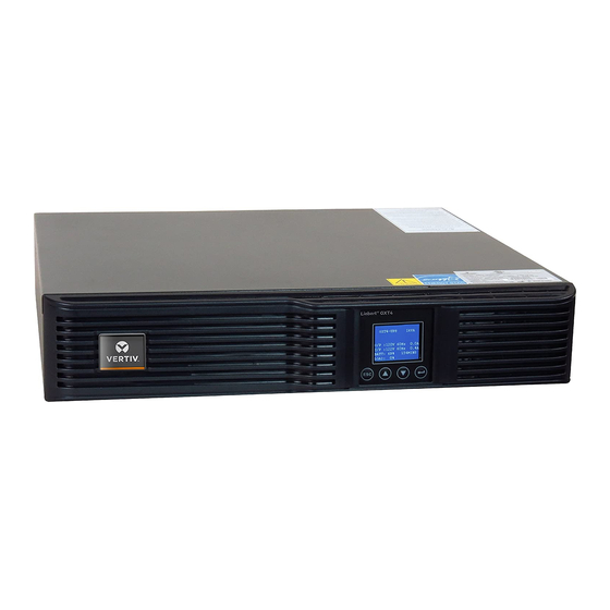
- Page 1 Liebert® GXT4™ UPS Installer/User Guide 120 V/208 V, 500 VA – 3000 VA...
- Page 2 The products covered by this instruction manual are manufactured and/or sold by Vertiv. This document is the property of Vertiv and contains confidential and proprietary information owned by Vertiv. Any copying, use or disclosure of it without the written permission of Vertiv is strictly prohibited.
-
Page 3: Table Of Contents
3.4.4 Connecting to AC Mains and Loads 3.4.5 Connecting Battery Cables 3.4.6 Connecting USB Communication Cables 3.4.7 Installing the Optional Liebert® IntelliSlot™ Card and Communication Cables 4 Operation and Display Panel 4.1 LED Indicators 4.2 Control Buttons 4.3 LCD Vertiv | Liebert® GXT4™ Installer/User Guide |... - Page 4 7.4 Checking UPS Status 7.5 Checking UPS Functions 8 Troubleshooting 8.1 Symptoms that Require Troubleshooting 8.1.1 Faults 8.1.2 Audible Alarm 8.2 Troubleshooting UPS Issues 9 Specifications 9.1 Auto-Learning Battery Run Times Appendices Appendix A: Technical Support Vertiv | Liebert® GXT4™ Installer/User Guide |...
-
Page 5: Important Safety Precautions
Do not continue to use the UPS if the front panel indications are not in accordance with these operating instructions or if the UPS performance alters in use. Refer all faults to your local dealer, Vertiv representative or Vertiv Channel Support. - Page 6 • Disconnect charging source prior to connecting or disconnecting battery terminals. • If the battery kit is damaged in any way or shows signs of leakage, contact your local Vertiv representative immediately. • Handle, transport and recycle batteries in accordance with local regulations.
- Page 7 Information for the Protection of the Environment UPS Servicing: UPS makes use of components dangerous for the environment (electronic cards, electronic components). The components removed must be taken to specialized collection and disposal centers. NOTICE TO EUROPEAN UNION CUSTOMERS: DISPOSAL OF OLD APPLIANCES—This product has been supplied from an environmentally aware manufacturer that complies with the Waste Electrical and Electronic Equipment (WEEE) Directive 2002/96/CE.
- Page 8 This page intentionally left blank Vertiv | Liebert® GXT4™ Installer/User Guide...
-
Page 9: Gxt4 Description
2 GXT4 DESCRIPTION The Liebert® GXT4 is a compact, online uninterruptible power system (UPS) that continuously conditions and regulates its output voltage. The Liebert® GXT4 supplies microcomputers and other sensitive equipment with clean sine-wave input power. Upon generation, AC power is clean and stable. However, during transmission and distribution it is subject to voltage sags, spikes, and complete failure that may interrupt computer operations, cause data loss, and damage equipment. -
Page 10: Front Panel And Controls
General Output Receptacles • Programmable Output Receptacles • Cable Strain-relief Attachment Hole • External Battery Connector • Cooling Fan • RS-232 port • Terminal Block Communication • Output Circuit Breakers (only on 3000 VA models) Vertiv | Liebert® GXT4™ Installer/User Guide... - Page 11 Figure 2.2 Rear panel components—120-V rack/tower, 500, 700, 1000 VA models DESCRIPTION DESCRIPTION Liebert® IntelliSlot port Programmable output receptacles #1 USB port General output receptacles Strain-relief attachment External battery connector Input power cable Cooling fan Input circuit breaker RS232 port Programmable output receptacles #2 Terminal block communication 2 GXT4 Description...
- Page 12 Liebert® IntelliSlot port General output receptacles USB port Strain-relief attachment Input circuit breaker External battery connector Input power cable Cooling fan Programmable output receptacles #2 RS-232 port Programmable output receptacles #1 Terminal block communication Vertiv | Liebert® GXT4™ Installer/User Guide...
- Page 13 Figure 2.4 Rear panel components—120-V rack/tower, 2000 VA models DESCRIPTION DESCRIPTION Liebert® IntelliSlot port Strain-relief attachment USB port External battery connector Input power cable Input circuit breaker Output receptacle (L5-20R) Cooling fan Not shown: 5-20P to L5-20R adapter Programmable output receptacles #2 RS232 port Programmable output receptacles #1 Terminal block communication...
- Page 14 Programmable output receptacles #1 USB port General output receptacles Output Strain-relief attachments Input circuit breaker External battery connector Input power plug and cable Cooling fan Output circuit breakers RS-232 port Programmable output receptacles #2 Terminal block communication Vertiv | Liebert® GXT4™ Installer/User Guide...
-
Page 15: Major Components
Figure 2.6 Rear panel components—208-V rack/tower, 3000VA DESCRIPTION DESCRIPTION Liebert® IntelliSlot port Programmable output receptacle 1, L6-15R USB port Programmable output receptacle 2, L6-15R Input power plug and cable, L6-20P Non-programmable output receptacle 1, L6-20R Input circuit breaker Cooling fan External battery connector RS232 port Output circuit breakers... -
Page 16: Transient Voltage Surge Suppression (Tvss) And Emi/Rfi Filters
The battery charger utilizes energy from the utility power and precisely regulates it to continuously float charge the batteries. The batteries are being charged whenever the GXT4 is plugged in, even when the UPS is not turned On. Vertiv | Liebert® GXT4™ Installer/User Guide... -
Page 17: Dc-To-Dc Converter
2.5.5 DC-to-DC Converter The DC-to-DC converter raises the DC voltage from the battery to the optimum operating voltage for the inverter. This allows the inverter to operate continuously at its optimum efficiency and voltage, thus increasing reliability. 2.5.6 Battery The GXT4 uses valve-regulated, non-spillable, lead acid batteries. To maintain battery design life, Operate the GXT4 in an ambient temperature of 32°F to 77°F (0°C to 25°C). -
Page 18: Operating Modes
NOTICE Risk of loss of power to the connected load. Can cause equipment damage. Turning Off the UPS in Bypass Mode will result in loss of output power to the connected load. Vertiv | Liebert® GXT4™ Installer/User Guide... -
Page 19: Battery Mode
2.6.3 Battery Mode The GXT4 enters Battery Mode when mains power fails or is outside acceptable limits. The battery system supplies power through the DC-to-DC converter to the inverter to generate clean AC power for the connected loads. When the GXT4 enters Battery Mode, the UPS sounds a half-second beep at 10-second intervals. When approximately 2 minutes of run time remains, the beeps sound every 5 seconds to warn that the battery is getting low (this Low Battery Warning is user-configurable). - Page 20 Once bypass power returns within the acceptable parameters, the UPS will return to Active ECO Mode operation. The default setting is Active ECO Mode Off. Vertiv | Liebert® GXT4™ Installer/User Guide...
-
Page 21: Installation
• Inspect the UPS for shipping damage. If any shipping damage is found, report it to the carrier and your local dealer or your Vertiv representative immediately. • Check the accessories included in packaging list. If there is any discrepancy, contact your local dealer or your Vertiv representative immediately. -
Page 22: Installation Clearances
Pull the logo on the front plastic bezel cover gently, rotate it 90 degrees clockwise and snap it back into position. d. Replace the front plastic bezel cover. The operation and display panel and logo have been rotated 90 degrees clockwise, for upright viewing. Vertiv | Liebert® GXT4™ Installer/User Guide... -
Page 23: Rack Installation
Figure 3.2 Remove the front plastic bezel cover and rotate display DESCRIPTION Remove bezel cover. Rotate display 90 degrees. 5. Place the GXT4 and any battery cabinets on the 2 support bases. Figure 3.3 Tower installation DESCRIPTION Panel rotated for tower operation. Support bases. -
Page 24: Connecting Cables
NOTE: If the input plug is to serve as the disconnecting device, the wall socket/outlet must be near the UPS and must be easily accessible, per the National Electric Code / NFPA 70 requirements. Vertiv | Liebert® GXT4™ Installer/User Guide... -
Page 25: Connecting Battery Cables
3.4.5 Connecting Battery Cables Verify that the battery isolation breaker is in the Off (open) position. 2. Take out the battery cable included with the battery cabinet. 3. Connect one end of the battery cable to the external battery connector on the rear panel of the UPS, and connect the other end to any battery port on the rear panel of the battery cabinet. - Page 26 3. To connect any cable associated with and IntelliSlot card, refer to the quick-installation guide provided with the card. To configure and use the Liebert® IntelliSlot communication card, refer to the card’s user manual. Find manuals online at http://www.VertivCo.com/en-us/support/. Vertiv | Liebert® GXT4™ Installer/User Guide...
-
Page 27: Operation And Display Panel
4 OPERATION AND DISPLAY PANEL The operation and display panel on the front of the GXT4 has control buttons, LED indicators and a liquid-crystal display (LCD). Figure 4.1 Operation and display panel DESCRIPTION DESCRIPTION Fault indicator ECO mode indicator Inverter indicator Enter button Battery indicator Down button... -
Page 28: Led Indicators
Pressing this button can enter the next level menu or confirm the parameter setting value. 4.3 LCD The LCD panel shows the UPS status and enables changes to the UPS settings by assisting in navigating through the GXT4 menu (see Menu Structure on the facing page). Vertiv | Liebert® GXT4™ Installer/User Guide... -
Page 29: Menu Structure
4.4 Menu Structure The menu structure of the LDC display is shown in the following figure. Figure 4.2 Menu structure 4 Operation and Display Panel... -
Page 30: Startup Screen
Select MAIN MENU > CONFIGURATION > UPS to enter the UPS screen. This menu has six screens. Press the Up or Down button to move the cursor to the required item, and press the Enter button to confirm the settings. Vertiv | Liebert® GXT4™ Installer/User Guide... - Page 31 Battery Screen Select MAIN MENU > CONFIGURATION > BATTERY to enter the BATTERY screen. This menu has four screens. Press the Up or Down button to increase or decrease the value of the settings, and press the Enter button to confirm it. ECO Mode Screen Select MAIN MENU >...
- Page 32 The NETWORK screen displays the MAC address and the IPv4 IP address. If the GXT4 is fitted with an optional Liebert® IntelliSlot Web card (Liebert IS-WEBCARD), the screen will display IPv6 IP address settings (IPv6 requires configuration). Vertiv | Liebert® GXT4™ Installer/User Guide...
-
Page 33: Prompt List
4.5 Prompt List A prompt screen is displayed during the operation of the system to alert you to certain conditions and/or to require your confirmation of a command or other operation. See the following table for the prompts and meanings. Table 4.3 System prompts and meanings PROMPT MEANINGS... -
Page 34: Warning List
Overtemperature occurs to the UPS and the UPS will transfer to Bypass mode. Charger Out Of Order The charger has failed. Fan Out Of Order At least one fan is failed. DC Bus Discharge Fail DC-DC failure occurs. Rectifier Out Of Order Rectifier failure occurs. Vertiv | Liebert® GXT4™ Installer/User Guide... - Page 35 If a fault occurs, the UPS automatically switches to Bypass Mode. The original operating mode will be maintained only in the case of a battery disconnection fault. The fault message alternates with UPS Mode once a second, the red fault indicator on the operation and display panel lights up and the alarm sounds continuously.
- Page 36 This page intentionally left blank Vertiv | Liebert® GXT4™ Installer/User Guide...
-
Page 37: Operation
If the battery test results show FAILED, allow the UPS to recharge the batteries for 24 hours. • Retest the batteries after 24 hours of charging. • After the batteries have been retested, if the battery test still shows FAILED, contact your local Vertiv representative or Technical Support. 5 Operation... -
Page 38: Performing Manual Bypass
3. Turn the external battery cabinet breaker switch to the Off position if the UPS has an external battery cabinet. After powering Off the UPS, the UPS ceases output and the load is powered Off. Vertiv | Liebert® GXT4™ Installer/User Guide... -
Page 39: Communication
6 COMMUNICATION This section describes the communication ports on the rear of the UPS: • Liebert® IntelliSlot™ port • USB port (standard B-type) • Terminal Block Communication • RS232 port (DB9F) CAUTION: To maintain safety (SELV) barriers and for electromagnetic compatibility, signal cables should be segregated and run separate from all other power cables. - Page 40 Set the Auto-Battery test to 8, 12, 16, 20, or 26 weeks (default is 8 weeks) • Select the number of external battery cabinets connected to the UPS to adjust the remaining run time calculated by Vertiv software products (default is zero) • Select one of multiple output voltages to match various voltages.
-
Page 41: Terminal Block Communication
6.3 Terminal Block Communication The Terminal Block includes eight pins, as shown the figure Figure 6.1 Terminal-block communication pin layout DESCRIPTION Any mode shutdown Battery-mode shutdown On battery mode Low battery mode 6.3.1 Any Mode Shutdown The purpose of Any Mode Shutdown is to shut down the UPS output by turning Off the rectifier, inverter and static switch so that there is no power to the loads. -
Page 42: Battery Mode Shutdown
Low Battery Warning time selected in the configuration program, this dry contact will be closed. The rated values for the dry contacts for the On Battery and Low Battery signals are: • Rated Voltage: 30 V (AC or DC) • Rated Current: 300 mA Vertiv | Liebert® GXT4™ Installer/User Guide... -
Page 43: Maintenance
• Disconnect charging source prior to connecting or disconnecting battery terminals. • If the battery kit is damaged in any way or shows signs of leakage, contact your Vertiv representative immediately. • Handle, transport, and recycle batteries in accordance with local regulations. -
Page 44: Battery Replacement Procedures
UPS is always in a restricted access location (such as a rack or server closet). Contact your local dealer or Vertiv representative to obtain the pricing of the appropriate replacement battery pack. CAUTION: Risk of explosion if battery is replaced by an incorrect type. Dispose of used batteries according to the instructions. - Page 45 6. Unpack the new internal battery pack. Take care not to destroy the packing. Compare the new and old internal battery pack to make sure they are the same type and model. If so, proceed with 7. If they are different, stop and contact your Vertiv representative, or Technical Support.
-
Page 46: Charging Batteries
• Check if the battery is discharging: When the utility input is normal, the battery should not discharge. If the UPS is operating in Battery Mode, stop and contact your Vertiv representative or Technical Support. Vertiv | Liebert® GXT4™ Installer/User Guide... -
Page 47: Checking Ups Functions
3. Press the On/Alarm Silence/Manual Battery Test button for three seconds after Inverter Mode. The UPS should initiate battery self-test. Check to determine whether the battery is operating normally. If not, stop and contact your Vertiv representative or Technical Support. 7 Maintenance... - Page 48 This page intentionally left blank Vertiv | Liebert® GXT4™ Installer/User Guide...
-
Page 49: Troubleshooting
8 TROUBLESHOOTING This section indicates various UPS symptoms you may encounter and provides a troubleshooting guide in the event the UPS develops a problem. Use the following information to determine whether external factors caused the problem and how to remedy the situation. 8.1 Symptoms that Require Troubleshooting The following symptoms indicate the UPS is malfunctioning: •... -
Page 50: Audible Alarm
1-second beep every 60 seconds 8.2 Troubleshooting UPS Issues In the event of an issue with the UPS, refer to the following table to determine the cause and solution. If the fault persists, contact Vertiv Technical Support. See Technical Support on page 63 Table 8.3 Troubleshooting table... - Page 51 When reporting a UPS issue to Vertiv, include the UPS model and serial number. These are located in several places for your ease of location: • on the top panel (rack mount orientation) •...
- Page 52 This page intentionally left blank Vertiv | Liebert® GXT4™ Installer/User Guide...
-
Page 53: Specifications
9 SPECIFICATIONS Table 9.1 Specifications for GXT4-500RT120, GXT4-700RT120 and GXT4-1000RT120 MODEL NUMBER GXT4-500RT120 GXT4-700RT120 GXT4-1000RT120 RATING 500VA/450W 700VA/630W 1000VA/900W Dimensions, D × W × H, in. (mm) 16.2 x 16.9 x 3.4 Unit (408 x 430 x 85) 25.5 x 23.9 x 10.6 Shipping (647 x 607 x 270) Weight, lb (kg) - Page 54 120-VAC nominal; variable based on output load variable based on output load 90 - 100% loading 102VAC/140VAC 177VAC/280VAC 70 - 90% loading 96VAC/140VAC 168VAC/280VAC 30 - 70% loading 84VAC/140VAC 150VAC/280VAC 0 - 30% loading 60VAC/140VAC 115VAC/280VAC Vertiv | Liebert® GXT4™ Installer/User Guide...
- Page 55 Table 9.2 Specifications forGXT4-1500RT120 to GXT4-3000RT120 and GXT4-3000RT208 (continued) MODEL NUMBER GXT4-1500RT120 GXT4-2000RT120 GXT4-3000RT120 GXT4-3000RT208 RATING 1500VA/1350W 2000VA/1800W 3000VA/2700W 3000VA/2700W Frequency 40 - 70Hz; Auto Sensing 10 ft. attached w/ 10 ft. attached w/ 10 ft. attached w/ 10 ft. attached w/ Input Power Cord NEMA L5-20P NEMA L5-30P...
- Page 56 High ambient temperatures will reduce battery life. Relative Humidity 0% to 95%, non-condensing Operating Elevation Up to 10,000 ft. (3000 m) at 104ºF (40ºC) without derating Storage Elevation 50,000 ft. (15000 m) maximum Agency Safety UL 1778, c-UL Listed Vertiv | Liebert® GXT4™ Installer/User Guide...
- Page 57 Table 9.3 Battery cabinet specifications (continued) MODEL NUMBER GXT4-48VBATT GXT4-72VBATT GXT4-500RT120, GXT4-700RT120, USED W/UPS MODEL GXT4-1000RT120, GXT4-1500RT120, GXT4-3000RT120, GXT4-3000RT208 GXT4-2000RT120 RFI/EMI FCC Class A Surge Immunity IEC 62040-2 2nd Ed Transportation ISTA Procedure 1A Table 9.4 Operating Temperature Parameters 25-30 30-35 35 - 40 AMBIENT TEMPERATURE, °C (°F)
- Page 58 PERCENT 208 VAC 120 VAC RT MODELS BATTERY RT MODELS CABINETS CAPACITY 500VA 700VA 1000VA 1500VA 2000VA 3000VA 3000VA Internal Battery + 1 External Battery Cabinet 100% 1319 1122 Internal Battery + 2 External Battery Cabinets 100% Vertiv | Liebert® GXT4™ Installer/User Guide...
- Page 59 Table 9.5 Battery run times (continued) NUMBER OF LOAD EXTERNAL PERCENT 208 VAC 120 VAC RT MODELS BATTERY RT MODELS CABINETS CAPACITY 500VA 700VA 1000VA 1500VA 2000VA 3000VA 3000VA 1809 1628 1209 1211 Internal Battery + 3 External Battery Cabinets 100% 2065 1926 1574 1284 1576...
-
Page 60: Auto-Learning Battery Run Times
The UPS will update the anticipated run time calculation only under certain conditions. • The UPS must have a steady load that is greater than 20%. • The UPS must be at 100% charge at the start of a battery discharge. Vertiv | Liebert® GXT4™ Installer/User Guide... - Page 61 • The battery discharge must continue uninterrupted until the batteries reach their end-of- discharge voltage. If all conditions are not met, the run time calculation will not be modified. If the configuration program is used to change the number of battery cabinets, then the values in the battery above table will be restored.
- Page 62 This page intentionally left blank Vertiv | Liebert® GXT4™ Installer/User Guide...
-
Page 63: Appendices
APPENDICES Appendix A: Technical Support Our Technical Support staff is ready to assist you with any installation or operating issues you may encounter with your Liebert® product. Please call or e-mail us: In Europe, Middle East, and Asia: EMEA Multi-Language Technical support: e: eoc@vertivco.com p: Toll free 0080011554499 p: Toll +39 02 98250222... - Page 64 This page intentionally left blank Vertiv | Liebert® GXT4™ Installer/User Guide...
- Page 65 Vertiv | Liebert® GXT4™ Installer/User Guide...
- Page 66 VertivCo.com | Vertiv Headquarters, 1050 Dearborn Drive, Columbus, OH, 43085, USA © 2018 Vertiv Co. All rights reserved. Vertiv and the Vertiv logo are trademarks or registered trademarks of Vertiv Co. All other names and logos referred to are trade names, trademarks or registered trademarks of their respective owners. While every precaution has been taken to ensure accuracy and completeness herein, Vertiv Co.
Need help?
Do you have a question about the Liebert GXT4 Series and is the answer not in the manual?
Questions and answers