Table of Contents
Advertisement
PELLET HYBRID GRILL
Model number: GR2297801-MM-00
ASSEMBLY & OPERATING INSTRUCTIONS
l This instruction manual contains important information necessary for the
proper assembly and safe use of the appliance.
l Read and follow all warnings and instructions before assembling/using the
appliance.
l Follow all warnings and instructions when using the appliance.
l Failure to follow these instructions and warnings could result in damage to the
product or injury to the user.
l Keep this manual for further reference.
For assistance, contact customer service at
1-888-837-1380
or at
For Outdoor Use Only
Should you encounter any problem,
CALL US FIRST.
Do not return product to the store.
WE CAN HELP.
, Mon to Fri, 8:00am – 5:00pm Pacific Standard time
1 of 51
customerservice@rankam.com
20181220-Ver.1.0
Advertisement
Table of Contents

Related Manuals for Rankam GR2297801-MM-00


Summary of Contents for Rankam GR2297801-MM-00
- Page 1 PELLET HYBRID GRILL Model number: GR2297801-MM-00 ASSEMBLY & OPERATING INSTRUCTIONS For Outdoor Use Only l This instruction manual contains important information necessary for the proper assembly and safe use of the appliance. l Read and follow all warnings and instructions before assembling/using the appliance.
- Page 2 WARNINGS SAFETY LABELS DANGER: Indicates an imminent hazardous situation which, if not avoided, will result in death or serious injury. WARNING: Indicates a potentially hazardous situation which, if not avoided, could result in death or serious injury. CAUTION: Indicates a potentially hazardous situation which, if not avoided, may result in minor or moderate injury.
-
Page 3: Prop 65 Warning
WARNING 1. Do not store or use gasoline or other flammable liquids or vapors in the vicinity of this or any other appliance. 2. An LP cylinder not connected for use shall not be stored in the vicinity of this or any other appliance. - Page 4 WARNING This outdoor cooking gas appliance shall be used only outdoors and shall not be used in a building, garage or any other enclosed area. This outdoor cooking gas appliance is not intended to be installed in or on boats. This appliance is not intended to be installed in or on recreational vehicles.
- Page 5 WARNING Use Only Wood Pellet Fuel Specified By The Manufacturer. Do Not Use Pellet Fuel Labeled As Having Additives. Never use gasoline, gasoline-type lantern fuel, kerosene, charcoal lighter fluid, or similar liquids to start or ’freshen up’ a fire in this appliance. Keep all such liquids well away from the appliance when in use.
-
Page 6: Before Installing
WARNING When using electrical appliances, basic safety precautions should always be followed, including the following: Electrical Rating: 120 Volts / 60 Hz / 10 A, Phase 1. Must be electrically grounded in accordance with local codes or, in the absence of local codes, with the National Electrical Code, ANSI/NFPA 70, or the Canadian Electrical Code, Part I, CSA C22.1 when install this appliance. - Page 7 LP tank valve requirement: Purchase LP tanks only with these required measurements: 12” (30.5cm) (diameter) x 18” (45.7cm) (tall) with 20lb. (9kg) capacity maximum. Type 1 outlet compatible with regulator or appliance. Safety relief valve. UL-listed Overfill Protection Device (OPD). This OPD safety feature is identified by a unique triangular hand wheel.
-
Page 8: Installing Gas Cylinder
WARNING FOR FILLING THE LP GAS CYLINDER Allow only qualified LP gas dealers to properly fill or repair your LP cylinder. DO NOT allow the cylinder to be filled beyond 80% capacity. Over-filled tanks can create a dangerous condition. Over-filled tanks can build up pressure and cause the relief valve to expel propane gas vapors. -
Page 9: Connection Procedures
CONNECTION PROCEDURES Make sure the tank valve is closed (turn valve clockwise until tight). Check the tank valve to insure it has the proper external male threads. Make sure all burner valves are turned OFF. Inspect valve connections, port, and regulator assembly. -
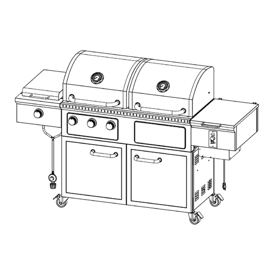
Page 10: Product Diagram
PRODUCT DIAGRAM 10 of 51 20181220-Ver.1.0... -
Page 11: Component List
COMPONENT LIST 1. Cooking Grate (Gas) 2. Cooking Grate (Pellet) 3. Warming Rack 2pcs 2pcs 2pcs 4. Flame Tamer (Gas) 5. Grease Cup (Gas) 6. Grease Drip Tray 3pcs 7. Flame Tamer (Pellet) 8. V-shaped Grease Drain 9. Grill Body Assembly 10. - Page 12 13. Side Burner Bracket 14. Match Holder 15. Side Burner Grease Tray 2pcs 16. Side Lid Handle 17. Side Burner Control Panel 18. Control Knob Bezel 2pcs 19. Control Knob 20. Cart Left Panel 21. Cart Left Rear Frame 22. Cart Right Rear Frame 23.
- Page 13 25. Cart Left Front Frame 26. Cart Right Front Frame 27. Cart Frame Connecting Tube 8pcs 28. Cart Side Rack 29. Cart Top Rack 30. Tank Holder 31. Left Door 32. Right Door 33. Locking Caster 4pcs 34. Cart Right Panel 35.
-
Page 14: Hardware List
37. Door Handle 38. Door Magnet Bracket 39. Meat Probe 2pcs 2pcs 2pcs HARDWARE LIST Item No. Item name Diagram M6x12mm Bolt M6 Nut M6x20mm Bolt M5x8mm Bolt M4x8mm Bolt Plastic Rivet M4x23 Step Bolt Note: For Bolt E, 12 pcs are stored in the hardware pack, and 2 pcs have been pre-attached on the related components. - Page 15 Replacement Part List (I) 15 of 51 20181220-Ver.1.0...
- Page 16 Replacement Part List (II) Part Part Name Part Part Name Number Number Cooking Grate (Gas) Cooking Grate (Pellet) Warming Rack Flame Tamer (Gas) Grease Cup (Gas) Grease Drip Tray Flame Tamer (Pellet) V-shaped Grease Drain Grill Body – Thermometer Grill Body Assembly Grill Body –...
- Page 17 Cart Right Front Frame Cart Frame Connecting Tube Cart Side Rack Cart Top Rack Tank Holder Left Door Right Door Locking Caster Cart Right Panel Plastic Insert Door Handle Bezel Door Handle Door Magnet Bracket Meat Probe Symbol: The following symbols will be shown in each procedure for indication of tightening the bolt and nut if necessary.
-
Page 18: Assembly Procedures
ASSEMBLY PROCEDURES Step 1 Connect the Cart Frames (21, 22, 25 & 26) with 8 pcs Cart Frame Connecting Tubes (27) as shown below then secure them with 16pcs M6x12 Bolts (A). Step 2 Attach the Cart Left Panel (20) to the cart assembly using 4pcs M6x12 Bolts (A). - Page 19 Step 3. Attach the Cart Right Panel (34) to the cart assembly using 4pcs M6x12 Bolts (A). Step 4 Attach the Cart Rear Panel (24) to the cart assembly using 10pcs M6x12 bolts (A). 19 of 51 20181220-Ver.1.0...
- Page 20 Step 5 Attach the Cart Base (23) to the cart assembly using 12pcs M6x12 bolts (A). Step 6 Insert the Locking Casters (33) into the threaded holes on the bottom of the cart assembly. Tighten the caster by turning in clockwise until it is fully secured.
- Page 21 Step 7 Fully tighten all the bolts in the cart assembly. Step 8 Attach the Tank Holder (30) to the cart assembly using 3pcs Plastic Rivets (F). 21 of 51 20181220-Ver.1.0...
- Page 22 Step 9 Connect the Cart Side & Top Racks (28 & 29) together using 3pcs M6x12 bolts (A) and 3pcs M6 Nuts (B). Step 10 Attach the cart rack assembly to the cart assembly using 5pcs M6x12 bolts (A). 22 of 51 20181220-Ver.1.0...
- Page 23 Step 11 Attach the Door Magnet Brackets (38) to the cart assembly using 4pcs M4x8 bolts (E). Step 12 Attach the Door Handle (37), Door Handle Bezels (36) and Plastic Inserts (35) to the Left Door (31) using 2pcs M6x20mm bolts (C). 23 of 51 20181220-Ver.1.0...
- Page 24 Step 13 Attach the Door Handle (37), Door Handle Bezels (36) and Plastic Inserts (35) to the Right Door (32) using 2pcs M6x20mm bolts (C). Step 14 Attach the doors to the cart assembly using 8pcs M4x8 bolts (E). Remark: Do not tighten the bolts until all the holes on the hinges are aligned and matched with the cart assembly.
- Page 25 Step 15 This step needs two people to complete! Make sure all casters are locked. Put the Grill Body Assembly (9) carefully on the top of cart assembly. Secure the grill body assembly using 4pcs M6x12mm bolts (A). Be careful to support the grill body and cart assembly during this step.
- Page 26 Step 17: Attach the Side Burner Assembly (12) to the grill body and lock it in place as shown. Step 18: Secure the side burner assembly by using 2pcs M6x12mm bolts (A). 26 of 51 20181220-Ver.1.0...
- Page 27 Step 19: Loosen the pre-assemble M4x8 bolts (E) at side burner gas valve as shown. Tips: Do not let the pre-assemble bolts get rid of the gas valve. It will help to proceed the next step. Step 20. Attach the side burner gas valve to the Side Burner Control Panel (17) and the Control Knob Bezel (18) using 2pcs pre-assemble M4x8 bolts (E).
- Page 28 Step 21. Insert the terminals of ignition wire for side burner to the connector of the side burner igniter. Attach the side burner control panel to the control panel bracket. Insert the valve outlet (orifice) into the side burner port. Make sure that the valve outlet is inserted STRAIGHTLY into the burner port as shown.
- Page 29 Step 22. Secure the side burner control panel to the grill body using 2pcs M6x12mm bolts (A). Step 23. Secure the side burner control panel to the side burner assembly using 1pc M6x12mm bolt (A). Secure the side burner supporting bar to the grill body using 1pc M6x12mm bolt (A).
- Page 30 Step 24. Insert the Control Knob (19) to the pins of side burner valve. Apply light pressure to secure the knob firmly. Make sure that the flat end of the pin is aligned with the D-shape hole in control knob (with the triangle pointing upwards).
- Page 31 Step 26. Attach the V-shaped Grease Drain (8) to the grill body using 4pcs M6x12mm bolts (A) as shown. Step 27. Attach the Flame Tamers (Gas) (4) and Flame Tamer (Pellet) (7) to the grill body. Place them in the holding brackets as shown. 31 of 51 20181220-Ver.1.0...
- Page 32 Step 28. Place the Grease Drip Tray (6) on the grill as shown. 32 of 51 20181220-Ver.1.0...
- Page 33 Step 29. Attach the Match Holder (14) to the grill body using 1pc M4x23 step bolt (G) as shown. Step 30. Place the Cooking Grates (1, 2 & 11) on the grill as shown below. 33 of 51 20181220-Ver.1.0...
- Page 34 Step 31. Place the Grease Cup & Bucket (5 & 10) and the Grease Tray (15) on the grill as shown below. Step 32. Your unit is fully assembled! Make sure to read and follow the Instruction Manual before operating this appliance. 34 of 51 20181220-Ver.1.0...
-
Page 35: Before Testing
OPERATING INSTRUCTIONS (GAS) LEAK TEST GENERAL Although all gas connections on the grill are leak tested at the factory prior to shipment, a complete gas tightness check must be performed after assembly to ensure fittings were not damaged after leaving the factory. Periodically check the entire system for leaks following the procedures listed below. -
Page 36: Lighting Instructions
LIGHTING INSTRUCTIONS BEFORE LIGHTING WARNING l Inspect the gas supply hose prior to turning the gas ON. l If there is evidence of cuts, wear, or abrasion, the hose must be replaced prior to use. l Do not use the grill if the odor of gas is present. l Only the pressure regulator and hose assembly supplied with the unit should be used. - Page 37 If ignition does NOT occur in 5 seconds, turn the burner controls off, wait 5 minutes, and repeat the lighting procedure. To turn burners off, turn the control knobs clockwise until they lock in the "OFF" position. LIGHTING INSTRUCTIONS (Side Burner) 1.
-
Page 38: Flame Characteristics
USING MATCH HOLDER TO LIGHT MAIN BURNER Turn OFF all burner valves. Make sure the lid is open. Place a lit match on the match holder and hold next to the main burner. Turn the control knob to the “HI” position. Burner should light immediately. -
Page 39: Initial Firing
OPERATING INSTRUCTIONS (PELLET) WARNING l Only Dia 6 mm Pellets can be used. LIGHTING INSTRUCTIONS 1. Read instructions before lighting. 2. Open lid during lighting. 3. Make sure power switch is in the "OFF" position. 4. Make sure control knob is in the "Shut Down Cycle" position. - Page 40 IF GRILL FAILS TO IGNITE: 1. Turn the control knob to the "Shut Down Cycle" position and turn the power switch OFF. 2. Wear the protective gloves and make sure all the components are cool to touch. Open lid, remove the cooking grates, grease drip tray and flame tamer. 3.
-
Page 41: Controller Operation
CONTROLLER OPERATION Shutdown Cycle: l Auger turns off. l Fan continues to run for 10 minutes. After finished cooking, turn the temperature control knob to “Shut Down Cycle” position, the function of this setting is leave the draft fan running for 10 minutes to burn redundant pellets in firepot. -
Page 42: Using Wood Pellet Fuel
8. We recommend you cover your grease drip tray with heavy-duty aluminum foil and change it frequently. This is the simplest way to maintain your grease drip tray. Failure to clean the grease drip tray, v-shaped grease drain and grease drain tube may cause grease fires. -
Page 43: Maintenance And Cleaning Instructions
MAINTENANCE & CLEANING INSTRUCTIONS CAUTION l Keep outdoor cooking gas appliance area clear and free from combustible materials, gasoline and other flammable vapors and liquids. l Do not obstruct the flow of combustible and ventilation air. l Keep the ventilation openings of the cylinder enclosure free and clear of debris. l Check and clean burner/venturi tubes for insects and insect nests. -
Page 44: Grill Burners
GRILL BURNERS Extreme care should be taken when removing a burner, as it must be correctly centered on the orifice before an attempt is made to relight the grill. Frequency of cleaning will depend on how often you use the grill. Spiders and small insects occasionally spin webs or make nests in the grill burner tubes during transit and warehousing. -
Page 45: Main Burner Replacement
MAIN BURNER REPLACEMENT 1. Remove the flame tamer. 2. Remove the burner cotter pin as shown. 3. Remove the carry over and the burner fixing pin. 4. Remove the burner from the grill body. Step 2 Step 4 TO REINSTALL THE MAIN BURNERS: 1. - Page 46 SIDE BURNER REPLACEMENT 1. Remove the flame tamer. 2. Remove the burner fixing bolts as shown. 3. Remove the burner from the grill body. Step 2 Step 3 TO REINSTALL THE SIDE BURNERS: 1. Insert the burner into the burner valve. 2.
- Page 47 PROPERLY INSTALL THE BURNER Firmly seat the valve orifice into the burner tube. Make sure the valve orifice is inserted STRAIGHTLY into the burner tube. Burner flames will be yellow, with excessive noise, lifting or flash back if the burner is not installed properly.
-
Page 48: Digtal Thermostat Control Wiring Diagram
DIGTAL THERMOSTAT CONTROL WIRING DIAGRAM 48 of 51 20181220-Ver.1.0... -
Page 49: Troubleshooting
TROUBLE SHOOTING Problem: Possible Causes: Corrective Actions: Burner will not 1. LP cylinder fuel is used up. 1. Change a new full LP cylinder. light 2. Electrode tip not in proper 2. Tip of electrode should be pointing position. toward gas port opening on burner. 3. - Page 50 Problem: Possible Causes: Corrective Actions: 1. Make sure the power cord is plugged in. Verify there is power at the electrical outlet. 2. Remove the control, check the fuse on back. Replace the fuse if blown out. 3. If both of the Draft Inducer Fan and 1.
-
Page 51: Limited Warranty
For assistance, contact customer service at 1-888-837-1380 , Mon to Fri, 8:00am – 5:00pm Pacific Standard time or at Manufacturer information Rankam (China) Manufacturing Company Limited Address: 18/F,. New Lee Wah Centre, 88 Tokwawan Road, Kowloon, Hong Kong. 51 of 51 20181220-Ver.1.0...
Need help?
Do you have a question about the GR2297801-MM-00 and is the answer not in the manual?
Questions and answers