Table of Contents
Advertisement
UI ROBOTIC WORKCELL
SETUP, OPERATION, AND PROGRAMMING OF
THE ENGINEERING DEPT. ROBOTIC WORKCELL
This instructional manual includes information on the DENSO Robotic arm and the modular
work-cell designed for it. Information discussed in this manual includes general information on
safety, manual operation, basic programming, and advanced programming using WINCAPS III
software.
Advertisement
Table of Contents

Related Manuals for Denso VS-6556G


Summary of Contents for Denso VS-6556G
- Page 1 SETUP, OPERATION, AND PROGRAMMING OF THE ENGINEERING DEPT. ROBOTIC WORKCELL This instructional manual includes information on the DENSO Robotic arm and the modular work-cell designed for it. Information discussed in this manual includes general information on safety, manual operation, basic programming, and advanced programming using WINCAPS III...
-
Page 2: Introduction
The Boeing Company INTRODUCTION DENSO Robotics Project History In the spring of 2013 The Boeing Company donated four DENSO robotic Steve Beyerlein arms to the College of Engineering. That fall Team Roboshow, learned programming and created a work-cell which incorporated multiple safety... -
Page 3: Table Of Contents
TABLE OF CONTENTS Introduction ............................... 1 Project History ............................1 Our Contribution ............................ 1 Table of Contents ............................. 2 DENSO VS-577G Specifications ......................3 Modular Work-cell design ......................... 4 Previous Design ............................ 4 New Modular Design ..........................4 Workcell Safety ............................5 OSHA Robotic Safety Standards ...................... -
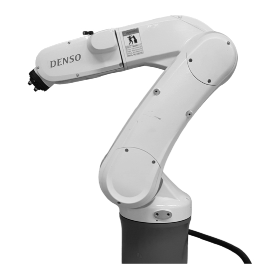
Page 4: Denso Vs-577G Specifications
DENSO VS-577G SPECIFICATIONS... -
Page 5: Modular Work-Cell Design
Previous Design In 2013 – 2014 Team Roboshow designed and fabricated a work-cell for one DENSO VS-G arm shown in Figure 1.1. Although this cell worked well for demonstration purposes two of its limitations were a slow settling time (being “wobbly”) and being difficult to reconfigure for... -
Page 6: Workcell Safety
WORKCELL SAFETY OSHA Robotic Safety Standards Summary of Occupational Safety and Health Administration Safety Standards related to robotics and safety enclosures. The below list includes all standards relevant to the UI Robotic Work-cell. 1910.144 Color identification Red- Danger, fire protection, emergency stop ... -
Page 7: E-Gard Interface
e-Gard Interface This device acts as an alternative interface to the controller along with providing extra safety precautions. The e-Gard system is connected to both the mini and safety I/O allowing for slight monitoring and external control of the robot. Solenoid Lock The features at the top of the e-Gard act as a door lock. -
Page 8: Using The Teach Pendant
USING THE TEACH PENDANT Powering Up the Workcell First ensure all I/O connections are secure: Teach Pendant “Enable Auto” Switch E-Gard Lockout Robot motor and encoder cable After this has been checked use the power switch to turn the unit on. The Power lamp will be lit if it is on Teach Pendant Controls... - Page 9 Deadman Switch The dead man switch is needed to control the robot in manual mode. It must be held down in order for the robot to move during manual operation. Release the switch to stop the robot, or press harder to stop it.
-
Page 10: Motion Mode
MOTION MODE There are three motion modes the robot is able to be operated in during manual mode: Joint mode, X-Y mode, and tool mode. The operation in Joint mode is shown above. Operation in X-Y mode and Tool mode assigns the buttons the following operations but with different origins: J1 –... -
Page 11: Programming With The Teach Pendant
PROGRAMMING WITH THE TEACH PENDANT Running a Stored Program In order to run a program that is stored on the Teach Pendant, first the program needs to be enabled. 1. Switch the Teach Pendant to Manual mode. 2. Touch the “Pgrm” button on the bottom of the Pendant screen and scroll to the desired program to ensure it is Enabled. -
Page 12: Importing Coordinates From The Arm's Current Position
Command Description PROGRAM Declares the program name to be run, this must match the file name MOTOR ON Turns on the robot’s motor so the operator does not have to do this manually TAKEARM This command specifies the program is taking control of the arm ‘... -
Page 13: Robot I/O
ROBOT I/O The robot is equipped with 2 air inputs, 10 signal lines, and 3 solenoid valves. One of the air inputs feeds the three solenoid valves and the other one is pass-through. The signal lines are able to electronically operate an end effector in the robot via logic programming. -
Page 14: Interpolation Control
INTERPOLATION CONTROL There are three different methods of movement that can be specified when telling the robot to move between two different points. Two of these were referenced in the example program that was run on the teach pendant (move p & move c). Below is a description of each movement type. PTP: Point to Point This can be defined as the movement from one point to another point. -
Page 15: Programming With Wincaps Iii
PROGRAMMING WITH WINCAPS III WINCAPS III is a powerful program used to do offline programming for DENSO Robotics. WINCAPS is capable of creating, editing, and simulating any program that can be performed by many of DENSO’s different robots. The program also offers extensive help and has built in tasks, such as pallet stacking, which can be tailored to the user’s specifications. -
Page 16: Writing A Program
Writing a Program After creating a project in WINCAPS a new program can be added. Do this by using the drop down menu under “Project” on the menu bar and select “Add Program”. A “Create New Program Prompt” will appear. The robot operates using *.PAC files, so choose to save the program in this format. -
Page 17: 3D View Pane
3D VIEW PANE Arm Operation The 3D view pane includes a project window with tabs for operating the simulated arm and populating the workspace with 3D parts. Using the arm operation window is similar to programming with the Teach Pendant, the same motion modes are used with the same coordinate systems. -
Page 18: Uploading Data From Wincaps To The Robot
Uploading Data from WINCAPS to the Robot To send data from WINCAPS to the RC7M controller (the robot’s brain), only the Toshiba laptop that comes with the workcell should be used due its specific network configuration settings. Below are the steps to transfer a project from the controller to the robot. -
Page 19: Appendix
APPENDIX Error Code Tables PAC Library...
Need help?
Do you have a question about the VS-6556G and is the answer not in the manual?
Questions and answers