Table of Contents
Advertisement
Quick Links
- 1 Standard Components
- 2 Robot Unit Components and Rotation Direction
- 3 Names of Robot Unit Components
- 4 Robot Specifications
- 5 Chapter 3 Specifications of the Robot Unit
- 6 Air Piping and Signal Wiring
- 7 Specifications
- 8 Controller Setting Table
- Download this manual
See also:
Installation and Maintenance Manual
Advertisement
Table of Contents

Related Manuals for Denso VP-G Series


Summary of Contents for Denso VP-G Series
- Page 1 ROBOT Vertical articulated VP-G SERIES GENERAL INFORMATION ABOUT ROBOT...
- Page 2 Copyright © DENSO WAVE INCORPORATED, 2005-2011 All rights reserved. No part of this publication may be reproduced in any form or by any means without permission in writing from the publisher. Specifications are subject to change without prior notice. All products and company names mentioned are trademarks or registered trademarks of their respective...
- Page 3 Preface Thank you for purchasing this high-speed, high-accuracy assembly robot. Before operating your robot, read this manual carefully to safely get the maximum benefit from your robot in your assembling operations. Robot series and/or models covered by this manual Series Model Mini-sized, vertical articulated VP-6242G (6-axis type)
- Page 4 How this book is organized This book is just one part of the robot documentation set. This book consists of SAFETY PRECAUTIONS, chapters one through five, and appendix. Chapter 1 Packing List of the Robot Lists the standard components contained in the product package and optional components. Chapter 2 Configuration of the Robot System Illustrates the configuration of the robot system and describes the component names of the robot unit and controller.
-
Page 5: Table Of Contents
Contents Chapter 1 Packing List of the Robot..........................1 1.1 Standard Components ............................1 1.2 Optional Components............................2 Chapter 2 Configuration of the Robot System....................... 4 2.1 Configurators ................................ 4 2.2 Names of Robot Unit Components ........................5 2.2.1 Robot Unit Components and Rotation Direction..................5 2.2.2 Name Plate.............................. -
Page 7: Chapter 1 Packing List Of The Robot
Chapter 1 Packing List of the Robot Chapter 1 Packing List of the Robot Standard Components The components listed below are contained in the product package. Standard Components Item Q'ty Robot unit Robot controller Power cable (5 m) Motor & encoder cable (Note 1) (Option) Manuals ("Manual Pack CD"... -
Page 8: Optional Components
Optional Components The table below lists the optional components. Optional Components Classification No. Item Remarks Part No. (8 m) Incl. Nos. 1-1 and 1-2. 410149-0940 Standard I/O cable set (15 m) Incl. Nos. 1-1 and 1-2. 410149-0950 (8 m) 410141-2700 1-1 I/O cable for “Mini I/O”... - Page 9 Shipped after integrated in the 410006-0800 EtherNet/IP function controller Board manufacturer: Hilscher GmbH Added when the board is Model: CIFX 50-RE\DENSO 410006-0810 purchased as a spare part Extension only upon controller Optional function for memory extension 410006-0320 shipment (3.25MB to 5.5MB)
-
Page 10: Chapter 2 Configuration Of The Robot System
Note 1: Components with numbers in () are the standard components contained in the product package listed on page 1. Note 2: The pendantless connector should be attached to the robot controller when no teach pendant or mini-pendant is connected. Configurators of the Robot System (VP-G series) -
Page 11: Names Of Robot Unit Components
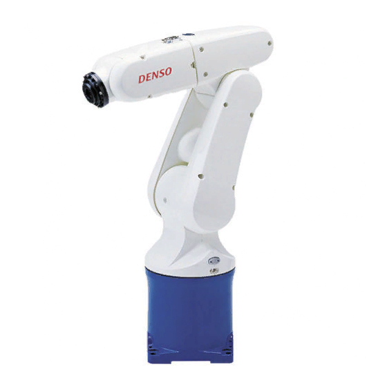
The figure below shows the names of the components of the robot unit and the rotation direction of each axis. Names of Components (VP-G series) NOTE: The flange (tool mounting face) of the robot unit may be coated with rust preventive oil which does not affect the robot function. -
Page 12: Name Plate
2.2.2 Name Plate The name plate is affixed in the base part, which includes serial number of the robot, robot model, and day of manufacturer, etc. The serial number is the figure which identifies the robot of each customer and it is paired with the figure of the controller. -
Page 13: Warning And Caution Labels
Chapter 2 Configuration of the Robot System 2.2.3 Warning and Caution Labels The robot unit has warning and caution labels pasted as shown below. They alert the user to the dangers of the areas on which they are pasted. Be sure to observe the instructions printed on those labels. -
Page 14: Names Of The Robot Controller Components
The figure below shows the names of the robot controller components. Note: For warning and caution labels pasted on the controller, refer to the RC7M CONTROLLER MANUAL. Connectors for the VP-G series (Encoders connected via bus) Connector No. Marking Name... -
Page 15: Chapter 3 Specifications Of The Robot Unit
Chapter 3 Specifications of the Robot Unit Chapter 3 Specifications of the Robot Unit Robot Specifications Following table list the robot unit specifications of the VP-G series. VP-G Series Specifications Specifications Item 6-axis type 5-axis type (Note 1) Model name of robot set (Note 2) -
Page 16: Outer Dimensions And Workable Space Of The Robot Unit
Outer Dimensions and Workable Space of the Robot Unit outer dimensions and workable space of the VP-G series are shown on the following pages. (1) VP-6242G (6-axis type) Outer Dimensions and Workable Space [VP-6242G]... - Page 17 Chapter 3 Specifications of the Robot Unit (2) VP-5243G (5-axis type) Outer Dimensions and Workable Space [VP-5243G]...
-
Page 18: Robot Positioning Time
Robot Positioning Time 1. Positioning time means the time from the start of robot operation to the arrival at the target positioning point. 2. After the robot moves to and passes the target positioning point, vibration will be dampened and the robot positioned at the target positioning point as shown in Figure below. -
Page 19: Vp-6242G Robot Positioning Time
Chapter 3 Specifications of the Robot Unit 3.3.1 VP-6242G robot positioning time J1 Axis [VP-6242G] J2 Axis [VP-6242G]... - Page 20 J3 Axis [VP-6242G] J4 Axis [VP-6242G]...
- Page 21 Chapter 3 Specifications of the Robot Unit J5 Axis [VP-6242G] J6 Axis [VP-6242G]...
- Page 22 CP Operation [VP-6242G]...
-
Page 23: Vp-5243G Robot Positioning Time
Chapter 3 Specifications of the Robot Unit 3.3.2 VP-5243G robot positioning time J1 Axis [VP-5243G] J2 Axis [VP-5243G]... - Page 24 J3 Axis [VP-5243G] J5 Axis [VP-5243G]...
- Page 25 Chapter 3 Specifications of the Robot Unit J6 Axis [VP-5243G] CP Operation [VP-5243G]...
-
Page 26: Air Piping And Signal Wiring
Air Piping and Signal Wiring The VP-G series is equipped with 4 air pipes for air chuck and 9 signal lines. The air piping and signal wiring of the VP-G series are shown in the figure below. NOTE: Maintenance and inspection of the robot unit sometimes requires removing and installing the covers. -
Page 27: Precautions When Designing The End-Effectors
Chapter 3 Specifications of the Robot Unit Precautions When Designing the End-effectors Design an end-effector such that it is in compliance with items (1) to (3) described below. CAUTION If the end-effector design precautions are not observed, the clamped parts of the robot unit may become loose, rattle or be out of position. - Page 28 (3) Moment of inertia around J4, J5 and J6 Design an end-effector so that its moments of inertia around J4, J5 and J6 (including workpiece) do not exceed the maximum allowable moment of inertia of the robot. Moment of inertia around J4, J5 and J6 of end-effector (incl. mass of workpiece) ...
- Page 29 Chapter 3 Specifications of the Robot Unit moment of inertia of a complicated shape, divide it into simple Calculation example : When calculating the parts as much as possible for easier calculations. As shown in the figure below, divide the end-effector into three parts (, , ). (1) Moment of inertia around J6 Around J6 d J6...
-
Page 30: Stopping Time And Distance (Angle) At An Emergency Stop
Stopping Time and Distance (Angle) at an Emergency Stop Pressing the emergency stop button when the robot is in motion stops the robot. The stopping time required from activation of a stop signal and the distance (angle) for major three joints vary with the robot speed as shown in the graphs below. The measuring conditions are: Robot arm extended, 33%, 66% and 100% of the maximum payload. - Page 31 Chapter 3 Specifications of the Robot Unit (2) VP-5243G series J1, J2, J3 stopping time vs. speed at an emergency stop (VP-5243G) J1, J2, J3 stopping distance vs. speed at an emergency stop (VP-5243G)
-
Page 32: Chapter 4 Specifications Of The Robot Controller
Chapter 4 Specifications of the Robot Controller Specifications Table below lists the robot controller specifications. RC7M Controller Specifications (1) (VP-G series) Item Specifications Mini-sized, vertical articulated type Mini-sized, vertical articulated type Applicable robot VP-6242G (6-axis type) VP-5243G (5-axis type) RC7M-VPG5/6CA*-**... - Page 33 Chapter 4 Specifications of the Robot Controller RC7M Controller Specifications (2) (VP-G series) Item Specifications Environmental conditions Temperature: 0 to 40C (in operation) Humidity: 90% RH or less (no condensation allowed) 200 VAC type: Three-phase, 200 VAC-15% to 230 VAC+10%, 50/60 Hz, 1 kVA...
-
Page 34: Outer Dimensions
Outer Dimensions Figure below shows the outer dimensions of the robot controller. Outer Dimensions of Robot Controller (VP-G series) Outer Dimensions of RC7M Robot Controller... -
Page 35: Controller Setting Table
The model of the robot system is entered. The coding of the set model is described below: SUBASSEMBLY The type and position of the controller IPM board are described. The coding of the set model (VP-G series) Vertical articulated robot, mini-sized... -
Page 36: Chapter 5 Warranty
The warranty shall be effective for one year from the date of purchase. Warranty Coverage DENSO WAVE shall repair the robot free of charge when a failure occurs and is attributable to the design, manufacture or material of the robot within the warranty period in spite of proper use. -
Page 37: Chapter 6 Appendix
Chapter 6 Appendix Chapter 6 Appendix Conformity with Standards by Robot Model For information on conformity with standards,contact your DENSO representative. - Page 39 Please feel free to send your comments regarding any errors or omissions you may have found, or any suggestions you may have for generally improving the manual. In no event will DENSO WAVE INCORPORATED be liable for any direct or indirect damages resulting from the application of the information in this manual.
Need help?
Do you have a question about the VP-G Series and is the answer not in the manual?
Questions and answers