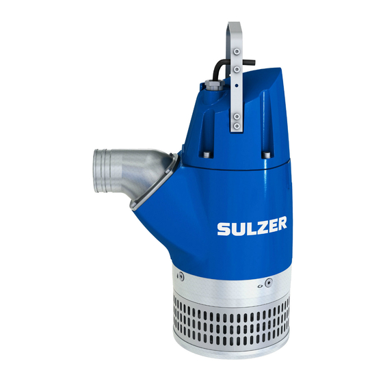
Sulzer XJ Series Workshop Manual
Submersible drainage pump
Hide thumbs
Also See for XJ Series:
- Assembly and installation instruction (4 pages) ,
- Starting and operating instructions (32 pages) ,
- Assembly and installation instruction (6 pages)

Related Manuals for Sulzer XJ Series


Summary of Contents for Sulzer XJ Series
- Page 1 Submersible drainage pump XJ Submersible drainage center-line pump XJC Submersible sludge pump XJS Workshop manual www.sulzer.com...
- Page 2 Workshop manual XJ 25 - 110, XJC 50 - 110, XJS 25 - 110 Submersible drainage pump XJ XJ 25 ND (50/60 Hz) XJ 25 HD (50/60 Hz) XJ 40 ND (50/60 Hz) XJ 40 HD (50/60 Hz) XJ 50 ND (50/60 Hz) XJ 50 HD (50/60 Hz) XJ 50 LD (50/60 Hz) XJ 80 ND (50/60 Hz)
-
Page 3: Table Of Contents
Workshop manual XJ 25 - 110, XJC 50 - 110, XJS 25 - 110 Contents General ..............................5 Service intervals ..........................5 AquaTronic version ..........................5 Repair kits and o-ring kits ........................5 Tools ..............................5 Complete pump overhaul ........................5 Cleaning of pump before service ....................... 5 Recycling in case of scrapping the pumps .................. - Page 4 Workshop manual XJ 25 - 110, XJC 50 - 110, XJS 25 - 110 Complete pump overhaul / assembly ................... 22 General ............................22 Assembly of ball bearings ........................ 22 Assembly of stator ..........................22 Secondary seal ..........................23 Primary seal and upper diffuser ....................... 23 Impeller ............................23 Assembly of diffuser .........................
-
Page 5: General
XJ 25-40, XJS 25-40: 00863349 XJ 50-110, XJC 50-110, XJS 50-110: 00863350 Tools The submersible drainage pumps can be maintained with standard tools. Sulzer does not recommend the use of impact tools for removal and installation of screws and nuts. Torque rating... -
Page 6: Recycling In Case Of Scrapping The Pumps
Workshop manual XJ 25 - 110, XJC 50 - 110, XJS 25 - 110 Recycling in case of scrapping the pumps Recycling of individual pump parts is beneficial to the environment. The pump can be fully dismantled for recycling. Alu- minium, stainless steel, ductile iron and high chrome cast iron can be recycled when a pump is scrapped. -
Page 7: Service Inspection
XJ 25 - 110, XJC 50 - 110, XJS 25 - 110 Service inspection Service Data Kit Contact Sulzer. Pump start and cable check Check the cable for damage and that there is no water or corrosion in the connecting plug. -
Page 8: Insulation Test
Workshop manual XJ 25 - 110, XJC 50 - 110, XJS 25 - 110 Insulation test Disconnect stator leads. Check that the contact points are not burned. Measure insulation resistance between the different phase windings, between windings and earth and between windings and thermal sensor circuit. The insulation resistance should be measured with 500 V megohmeter (megger) and the reading should be at least 1 MΩ. -
Page 9: Thermal Sensors
Workshop manual XJ 25 - 110, XJC 50 - 110, XJS 25 - 110 Thermal sensors The circuit thermal sensors with the two built-in NTC thermistors (TU1+TV1) S , used when pumps are equipped with AquaTronic, should be checked for continuity, using an ohmmeter. At 25ºC = 47 kOhm. The circuit, used when pumps are equipped with DS contactor, with the two thermal contacts (TC1+TC2) T should be checked for continuity, using an ohm- meter or buzzer. -
Page 10: Oil / Motor Check
Workshop manual XJ 25 - 110, XJC 50 - 110, XJS 25 - 110 Oil / Motor check AquaTronic version See separate manual for Service Diagnostic Program. Standard version and AquaTronic version Unscrew the two oil plugs and drain off the oil in a clean can and inspect it. Oil should be clear and without impurity. For refilling of oil see chapter 8.9. -
Page 11: Hydraulic Check
Workshop manual XJ 25 - 110, XJC 50 - 110, XJS 25 - 110 Hydraulic check If the test run against shut of head shows that the pump is not close to expected head a hydraulic check is needed. Wear ring ND, HD 4.1.1 Adjustment of wear ring CAUTION! -
Page 12: Diffuser Nd, Hd, Ld
Workshop manual XJ 25 - 110, XJC 50 - 110, XJS 25 - 110 Diffuser ND, HD, LD 4.2.1 Dismantling of diffuser Remove the screws which hold the upper diffuser and bear- Check the diffuser for scratches. The rubber should have a ing house together. -
Page 13: Impeller Nd, Hd, Ld
Workshop manual XJ 25 - 110, XJC 50 - 110, XJS 25 - 110 Impeller ND, HD, LD 4.3.1 Dismantling of impeller Hold the impeller with a large screwdriver or similar, be- Pry the impeller loose with two screwdrivers under the im- tween the vanes and unscrew the impeller washer. -
Page 14: Xj 80 Sd, Change Of Diffusers, Impellers And Guide Vane Plate
Workshop manual XJ 25 - 110, XJC 50 - 110, XJS 25 - 110 XJ 80 SD, change of diffusers, impellers and guide vane plate Dismantling Turn the pump upside down Loosen the bottom nuts and Loosen the dual nuts and washers that hold the lower dif- remove the base plate and the rubber sleeves. -
Page 15: Assembly
Workshop manual XJ 25 - 110, XJC 50 - 110, XJS 25 - 110 Remove the distance sleeve between the impellers and Pull out the upper diffuser. Turn the impeller so the three pull out the guide vane plate. Note the number of 0.5 shims marks on the impeller side meet the channels of the wear on top of the distance sleeve before removing them, also plate. - Page 16 Workshop manual XJ 25 - 110, XJC 50 - 110, XJS 25 - 110 Mount the lower diffuser on the stud bolts and screw two Grease and mount o-ring on the oil casing. Put the strainer screws onto each stud bolt. Check that the distances are in place and then the rubber sleeves and the base plate.
-
Page 17: Primary Seal And Upper Diffuser
Workshop manual XJ 25 - 110, XJC 50 - 110, XJS 25 - 110 Primary seal and upper diffuser Dismantling of primary seal and upper diffuser Remove the circlip and pull out the rotating part of the pri- Withdraw the upper diffuser by using two screwdrivers. mary seal. - Page 18 Workshop manual XJ 25 - 110, XJC 50 - 110, XJS 25 - 110 Place the rubber foam in the bearing house. Grease and Grease and mount a new primary seal o-ring on the shaft. mount o-ring on the bearing house, and mount upper dif- Oil the sealing surfaces of the mechanical seal and push fuser with screws.
-
Page 19: Complete Pump Overhaul / Dismantling
Workshop manual XJ 25 - 110, XJC 50 - 110, XJS 25 - 110 Complete pump overhaul / dismantling Perform all dismantling operation in chapter 2 then continue with:. Electronics 7.1.2 Standard version 7.1.1 AquaTronic version Turn the pump and remove AquaTronic Turn the pump and remove the contactor from the omega rail. -
Page 20: Rotor Unit
Workshop manual XJ 25 - 110, XJC 50 - 110, XJS 25 - 110 Rotor unit 7.4.1 Dismantling of rotor unit. 11 (2x) Lifting tool for XJ 50 - XJ 110. Remove the jacket (for easy dismantling of jacket use lifting Remove the jacket on XJC. -
Page 21: Dismantling Of Ball Bearings
Workshop manual XJ 25 - 110, XJC 50 - 110, XJS 25 - 110 Dismantling of ball bearings Remove upper bearing with a ball bearing puller tool. Remove the circlip and press out the bearing. Make sure to support the bearing house properly. Stator 7.6.1 Insulation check... -
Page 22: Complete Pump Overhaul / Assembly
Workshop manual XJ 25 - 110, XJC 50 - 110, XJS 25 - 110 Complete pump overhaul / assembly General Clean all parts carefully, especially o-ring groves and mating surfaces. Grease or oil o-rings to eliminate damage during assembly. Grease or oil screw threads to simplify disassembly during future overhaul. -
Page 23: Secondary Seal
Workshop manual XJ 25 - 110, XJC 50 - 110, XJS 25 - 110 Sensor cables Motor cables When the housing has been mounted it may be cooled by Press rotor with shaft in place in the bearing house (with compressed air. -
Page 24: Refilling Of Oil
Workshop manual XJ 25 - 110, XJC 50 - 110, XJS 25 - 110 Refilling of oil Fill all the way up to entrance of oil inspection hole. Make sure to fill in oil chamber marked with an oil drop. Tighten the oil plug with a new o-ring Use Paraffin oil (white oil) with viscosity 10-15 cSt, e.g. -
Page 25: Assemble The Top Cover
Workshop manual XJ 25 - 110, XJC 50 - 110, XJS 25 - 110 8.11 Assemble the top cover Grease and mount the o-ring on the cover. Mount the cover on the jacket and arrange the leads so that they may not be jammed or block the functioning of the contactor. -
Page 26: Electrical Information And Wiring Diagrams
Workshop manual XJ 25 - 110, XJC 50 - 110, XJS 25 - 110 Electrical information and wiring diagrams 10.1 Three phase Direct Start D.O.L. with contactor The stators are wound for different voltages and can be internally Delta- or Star-connected. The contactor is activated by the same voltage as the supply voltage. -
Page 27: Three Phase Direct Start D.o.l. With Aquatronic
Workshop manual XJ 25 - 110, XJC 50 - 110, XJS 25 - 110 10.2 Three phase Direct Start D.O.L. with AquaTronic The stators are wound for different voltages and can be internally Delta- or Star-connected. (XJ 25) (XJ 25-40) (XJ 25-50) (XJ 25-80) 00833234AC... -
Page 28: Three Phase Soft Start With Aquatronic
Workshop manual XJ 25 - 110, XJC 50 - 110, XJS 25 - 110 10.3 Three phase Soft Start with AquaTronic. The stators are wound for different voltages and can be internally Delta- or Star-connected. 230V 50/60Hz 380V60Hz 400V 50hz 460V 60Hz 00833235AC Figure 6: Soft Start with AquaTronic. -
Page 29: Three Phase Direct Start D.o.l. With Terminal Block
Workshop manual XJ 25 - 110, XJC 50 - 110, XJS 25 - 110 10.4 Three phase Direct Start D.O.L. with terminal block The stators are wound for 230 V or 460 V 50 Hz and connected Star. (Figure 7).The stators are wound for 1000 V 50 Hz and connected Star. -
Page 30: Winding Data
Workshop manual XJ 25 - 110, XJC 50 - 110, XJS 25 - 110 10.5 Winding data... -
Page 31: Fuses
Workshop manual XJ 25 - 110, XJC 50 - 110, XJS 25 - 110 10.6 Fuses Fuses are to be installed in the power circuits as a short circuit protection. Fuses with a time lag are recommended. The table shows the nominal current and starting current factor. Multiply factor with nominal current to get the pumps starting current. -
Page 32: Sectional Drawing
Workshop manual XJ 25 - 110, XJC 50 - 110, XJS 25 - 110 Sectional drawing Contactor AquaTronic Ball bearing, upper Motor housing Stator Ball bearing, lower Bearing house Upper di user Rotor and shaft Lower di user Impeller Wear ring... - Page 33 Workshop manual XJ 25 - 110, XJC 50 - 110, XJS 25 - 110 Contactor AquaTronic Ball bearing, upper Motor housing Stator Ball bearing, lower Rotor and shaft Bearing house Di user Volute Impeller...
-
Page 34: Troubleshooting
Workshop manual XJ 25 - 110, XJC 50 - 110, XJS 25 - 110 Troubleshooting 12.1 Troubleshooting in field Error Probable cause Solution Dead incoming power lines. Check power lines. Blown fuses or breakers. Check fuses and breakers. The pump will not start. Phase failure. -
Page 35: Troubleshooting/Service Inspection With Service Diagnostic Program For Aquatronic
Workshop manual XJ 25 - 110, XJC 50 - 110, XJS 25 - 110 Defective shaft seal. Change primary seal. Faulty assembly of o-rings, mechanical Replace parts. Water in the oil chamber. seal or upper diffuser. Worn seals. Replace parts and dry motor. 5 + 7 Pump operating at too low Worn or damaged impeller and/or wear... - Page 36 Sulzer Pump Solutions Ireland Ltd, Clonard Road, Wexford, Ireland Tel +353 53 91 63 200, www.sulzer.com Copyright © Sulzer Ltd 2019...
Need help?
Do you have a question about the XJ Series and is the answer not in the manual?
Questions and answers