Sign In
Upload
Manuals
Brands
Newport Manuals
Controller
ESP300 Series
Newport ESP300 Series Manuals
Manuals and User Guides for Newport ESP300 Series. We have
1
Newport ESP300 Series manual available for free PDF download: User Manual
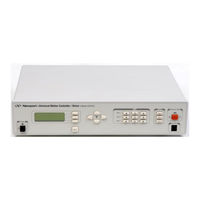
Newport ESP300 Series User Manual (314 pages)
Motion Controller/Driver
Brand:
Newport
| Category:
Controller
| Size: 5.55 MB
Table of Contents
Warranty
2
Limitation of Warranty
2
EU Declaration of Conformity
4
Table of Contents
5
Section 1 - Introduction
15
Scope
15
Safety Considerations
16
Conventions and Definitions
17
Definitions and Symbols
17
Terminology
19
System Overview
20
Features
20
Specifications
21
Descriptions of Front Panel Versions
22
Rear Panel Description
23
Figure 1.3: Rear Panel of the ESP300
24
System Setup
25
Line Voltage
25
First Power on
25
Quick Start
26
Connecting Motion Devices
26
Motor on
27
Homing
27
First Jog
28
Section 2 - Modes of Operation
31
Overview of Operating Modes
31
LOCAL Mode
31
REMOTE Mode
31
Operation in LOCAL Mode
32
Accessing the Menu
32
Navigating the Menu
32
Changing Values
32
Motion from the Front Panel
33
Detailed Description of Menu Items
35
Section 3 - Remote Mode
41
Programming Modes
41
Remote Interfaces
44
IEEE488 Interface
45
Software Utilities
46
Command Syntax
47
Summary of Command Syntax
48
Command Summary
49
AB Abort Motion
50
Table 3.5.2: Command List - Alphabetical
55
AC Set Acceleration
57
Description of Commands
57
AE Set E-Stop Deceleration
63
AF Set Acceleration Feed-Forward Gain
65
AP Abort Program
68
BA Set Backlash Compensation
70
BG Assign DIO Bits to Execute Stored Programs
71
BK Assign DIO Bits to Inhibit Motion
73
BL Enable DIO Bits to Inhibit Motion
73
BM Assign DIO Bits to Notify Motion Status
74
BN Enable DIO Bits to Notify Motion Status
75
BO Set DIO Port A, B Direction
76
BP Assign DIO Bits for Jog Mode
79
BQ Enable DIO Bits for Jog Mode
79
CL Set Closed Loop Update Interval
82
DB Set Position Deadband
82
DC Setup Data Acquisition
83
DD Get Data Acquisition Done Status
84
DE Enable/Disable Data Acquisition
86
DF Get Data Acquisition Sample Count
86
DG Get Acquisition Data
88
DH Define Home
89
DL Define Label
90
DO Set Dac Offset
91
DP Read Desired Position
92
EO Automatic Execution on Power on
94
EP Enter Program Mode
95
ES Define Event Action Command String
96
EX Execute a Program
98
ST Stop Motion
138
SU Set Encoder Resolution
173
TB Read Error Message
178
TE Read Error Code
179
TJ Set Trajectory Mode
180
TP Read Actual Position
181
TS Read Controller Status
182
TV Read Actual Velocity
183
TX Read Controller Activity
184
UF Update Servo Filter
185
UH Wait for DIO Bit High
186
UL Wait for DIO Bit Low
187
VA Set Velocity
188
VB Set Base Velocity for Step Motors
189
VE Read Controller Firmware Version
190
VF Set Velocity Feed-Forward Gain
191
VU Set Maximum Velocity
192
WP Wait for Position
193
WS Wait for Motion Stop
193
WT Wait
193
XM Read Available Memory
196
Erase Program
197
ZA Set Amplifier I/O Configuration
198
ZB Set Feedback Configuration
201
ZE Set E-Stop Configuration
206
ZH Set Hardware Limit Configuration
207
ZS Set Software Limit Configuration
212
ZZ Set System Configuration
212
Grouping
215
Defining Group Parameters
216
Making Linear Move
217
Making Contours
218
Figure 4.1: a Contour with Multiple Circular Moves
219
Figure 4.3: Block Diagram of Via Point Data Handling by Command Processor
220
Miscellaneous Commands
221
Table 4.1: Slave to a Different Stage Steps
222
Table 4.2: Slave to a Trackball Steps
223
Table 4.3: Slave to a Joystick Steps
223
Feature Implementation
224
Table 4.4: an Example of Closed Loop Stepper Motor
225
Figure 4.5: Block Diagram of Closed Loop Stepper Motor Positioning
225
Table 4.5: Closed Loop Stepper Positioning Commands
226
Synchronize Motion to External and Internal Events
226
Using DIO to Inhibit Motion
228
Table 4.6: Commands to Synchronize Motion to External Events
229
Motion Systems
231
Specification Definitions
232
Following Error
233
Local Accuracy
234
Figure 5.3A: High Accuracy for Small Motions
235
Resolution
236
Repeatability
237
Figure 5.7: Hysteresis Plot
238
Pitch, Roll and Yaw
239
Wobble
240
Maximum Velocity
241
Velocity Regulation
242
Combined Parameters
243
PID Servo Loops
244
Figure 5.14: P Loop
245
Feed-Forward Loops
246
Figure 5.17: Trapezoidal Velocity Profile
247
Motion Profiles
248
Figure 5.20: Trapezoidal Motion Profile
249
Home Search
250
Figure 5.22: Home (Origin) Switch and Encoder Index Pulse
251
Encoders
252
Figure 5.26: Encoder Quadrature Output
253
Figure 5.28: Optical Encoder Read Head
254
Figure 5.30: Two-Channel Optical Encoder Scale and Read Head Assembly
255
Motors
256
Figure 5.32: Four-Phase Stepper Motor
257
Figure 5.34: Energizing Two Phases Simultaneously
258
Figure 5.37: Timing Diagram, Continuous Motion (Ideal)
259
Figure 5.39: Single Phase Energization
260
Stepper Motor Types
261
DC Motors
262
Drivers
263
Figure 5.44: Simple Stepper Motor Driver
264
Unipolar-Bipolar Drivers
265
DC Motor Drivers
266
Figure 5.50: DC Motor Current Driver
267
PWM Drivers
268
Tuning Principles
269
Correcting Axis Oscillation
270
Points to Remember
272
Table 6.1: Servo Parameter Functions
273
Hand-Held Keypad
275
Description of Keys
276
Appendix A – Error Messages
277
Appendix B – Trouble-Shooting/Maintenance
285
Table B.1: Trouble-Shooting Guide Descriptions
286
B.2 Fuse Replacement
288
B.3 Cleaning
289
Table C.1: Digital Connector Pin-Outs
291
Appendix C – Connector Pin Assignments
291
Table C.2: Driver Card Connector Pin-Outs
292
C.1.3 Motor Driver Card (25-Pin) I/O Connector
292
C.1.4 Signal Descriptions (Motor Driver Card 25-Pin I/O Connector)
293
C.1.5 Auxiliary Encoder Inputs
295
Table C.3: Auxiliary Encoder Connector Pin Outs
296
Table C.4: IEEE488 Interface Connector
296
C.1.7 RS-232C Interface Connector (9-Pin D-Sub)
296
C.1.8 RS-232C Interface Cable
297
Figure C.3: Motor Interlock Connector (BNC) with Dust Cap
298
Table D.1: Binary Conversion Table, Using Decimal and
299
Appendix D – Binary Conversion Table
299
Appendix E – System Upgrades
305
E.1 Adding Axes
306
E.2 Adding IEEE488
307
E.3 Changing the Front Panel Option
308
Appendix F – ESP Configuration Logic
309
Figure F.1: Configuration Logic
310
Appendix G – Programming Non-ESP Compatible Stages
311
Table H.1: Technical Customer Support Contacts
313
Appendix H – Factory Service
313
H.1 Service Form
314
Advertisement
Advertisement
Related Products
Newport ESP301
Newport ESP300-1 Series
Newport ESP300-2 Series
Newport ESP302
Newport ESP6000
Newport e360
Newport Breeze E150
Newport Elite 3
Newport OPHIR EA-1
Newport 6000
Newport Categories
Controller
Measuring Instruments
Receiver
Industrial Equipment
Amplifier
More Newport Manuals
Login
Sign In
OR
Sign in with Facebook
Sign in with Google
Upload manual
Upload from disk
Upload from URL