Table of Contents
Advertisement
—
A B B M E A S U R E M E N T & A N A LY T I C S | O P E R AT I N G I N S T R U C T I O N
JDF200
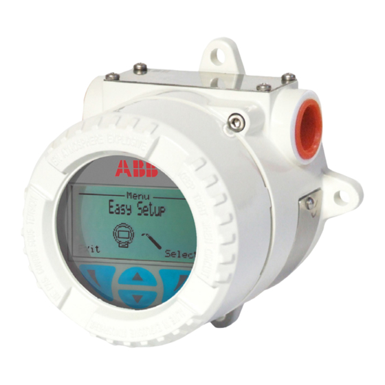
Field indicator
—
Introduction
JDF200 indicator
Model JDF200 field indicator provides simple and
low cost remote indication of a process variable on
an easy to read meter, ensuring the most useful
display for any specific application..
Engineered solutions for all
applications
Measurement made easy
For more information
Further publications for JDF200 field indicator are
available for free download from www.abb.com/
pressure
Advertisement
Table of Contents

Related Manuals for ABB JDF200


Summary of Contents for ABB JDF200
- Page 1 — Introduction For more information JDF200 indicator Model JDF200 field indicator provides simple and Further publications for JDF200 field indicator are low cost remote indication of a process variable on available for free download from www.abb.com/ an easy to read meter, ensuring the most useful pressure display for any specific application..
- Page 2 We are an established world force in the design and manufacture of measurement products for industrial process control, flow measurement, gas and liquid analysis and environmental applications. As a part of ABB, a world leader in process automation technology, we offer customers application expertise, service and support worldwide.
-
Page 3: Table Of Contents
11.6.3 Special conditions ..........30 11.7 Ex Safety aspects and IP Protection (Canada) ...31 11.7.1 Applicable standards .........31 11.7.2 Classifications ...........31 11.7.3 Special conditions ..........31 11.8 ETL marking and entities ..........32 1.13 Trouble Sheet ..........33 2600T Series | OI/JDF200-EN Rev. E 3... -
Page 4: Introduction
2.2 1.2 Models covered by this manual The present manual can be used for JDF200 Field Indicator. 2.3 1.3 Product description Model JDF200 Field Indicator provides simple and low cost remote indication of a process variable on an easy to read LCD display. -
Page 5: General Safety Information
This message indicates a potentially Warning – <Bodily injury>. For safety reasons, ABB draws your attention to the fact that only dangerous situation. Failure to avoid this could result in death or sufficiently insulated tools conforming to DIN EN 60900 may be serious injury used. -
Page 6: Operator Liability
Therefore, the auxiliary power must be shipping purposes. switched off before opening the housing cover. All devices sent back to ABB must be free from any hazardous Corrective maintenance work may only be performed by trained materials (acids, alkalis, solvents, etc.). -
Page 7: Field Indicator Overview
3 Transmitter overview 4 3 Field indicator overview 4.1 3.1 Field indicator components overview 1 - LCD display with keypad (L1 option) 2 - Terminal block / conversion board Figure 1: Field Indicator components 2600T Series | OI/JDF200-EN Rev. E 7... -
Page 8: Opening The Box
The optional, additional wired-on SST Tag plate (ref. C - code I2) can be filled with customized data. JDF200 field indicator is in compliance with EMC 2014/30/UE. The certification plate (ref.A) shown here is issued by ABB S.p.A, 22016 Tremezzina, Italy, with the numbers: —... -
Page 9: Mounting
Ex ta IIIC Tx Da IP67 6.2 5.2 IP protection & designation — Non-sparking The housings for JDF200 Field Indicator The field indicator is dust US: Class I, Zone 2 AEx nA IIC T6...T4 Gc and sand tight and protected against immersion effect as defined by IEC60529 to IP67 or by NEMA Type 4X. -
Page 10: Bracket Mounting
107 (4.21) 26 (1.02) 55 (2.17) Figure 3: JDF200 field indicator installed on a horizontal or vertical pipe with optional bracket 6.5.2 5.4.2 BB Stainless steel U-bolt for pipe fixing 6.6 5.5 Securing the housing cover in flameproof The U-bolt and nuts supplied are necessary for the installation areas on pipe. -
Page 11: Field Indicator Wiring
Observe the applicable regulations governing electrical installation. Connections must only be established in a dead-voltage state. JDF200 field indicator has overvoltage/lightening according to IEC 61326 (higher capacity must be provided at the plant). Check that the existing operating voltage corresponds to the needed voltage. The same lines are used for both the power supply and output signal. -
Page 12: Supply Requirement
The most effective field indicator case grounding method is higher currents, the display will show 23 mA. direct connection to earth ground with impedance equal or less JDF200 can withstand up to 400mA for a short period of time of 5 ohm. without damage. -
Page 13: Operation
LCD display above the respective button. — You can browse through the menu or select a number within a parameter value using both keys (2) and (3) . The button (4) selects the desired menu item. 2600T Series | OI/JDF200-EN Rev. E 13... - Page 14 This menu allows the parameterization of the process alarm. The menu-driven structure will guide you through the setting of saturation and alarm limits as well as the customization of Service menu is to be used by ABB personnel only and allows alarm messages. JDF200 detailed configuration visualization.
-
Page 15: Easy Set-Up
7 Operation 8.3.1 7.3.1 Easy 2600T Series | OI/JDF200-EN Rev. E 15... - Page 16 7 Operation 16 OI/JDF200-EN Rev. E | 2600T Series...
- Page 17 7 Operation 2600T Series | OI/JDF200-EN Rev. E 17...
-
Page 18: Device Set-Up
7 Operation 8.3.2 7.3.2 Device 18 OI/JDF200-EN Rev. E | 2600T Series... - Page 19 7 Operation 8.3.3 7.3.3 Process 2600T Series | OI/JDF200-EN Rev. E 19...
-
Page 20: Diagnostics
7 Operation 8.3.4 7.3.4 8.3.5 7.3.5 Device 8.3.6 7.3.6 20 OI/JDF200-EN Rev. E | 2600T Series... -
Page 21: Process Alarm
8.4.3 7.4.3 Square root to the 3 power Using this function, the relation between the indicator scale / JDF200 provides a selection of output functions, as follows: output value and the input value is square root to the 3 power. -
Page 22: Error Messages
Input current exceeding HiHi or LoLo F240.000 Check cable connection, check connected device and/or process. alarm limits Input current exceeding LoHi or HiLo C150.001 Check cable connection, check connected device and/or process. alarm limits 22 OI/JDF200-EN Rev. E | 2600T Series... -
Page 23: Maintenance
The use of non original spare parts makes the warranty void. In electricity in your body is discharged when touching electronic case you want ABB to perform the repair, please send back the components. field indicator to your local ABB office complete with the return form that you find in this manual appendix and include it with the device. -
Page 24: Hazardous Area Considerations
V= 30 Vdc V= 30 Vdc V= 30 Vdc Limited at 58mA Limited at 95mA Limited at 58mA Limited at 28mA Fuse : 50mA Fuse : 90mA Fuse : 50mA Fuse : 25mA 24 OI/JDF200-EN Rev. E | 2600T Series... - Page 25 Note: the field indicator can be connected to either [ib] or [ia] Note: the protection is mainly assured by the “IP” degree supply (associated apparatus)certified [Ex ia] associated to the low power from supply. This can either be [ia] or [ib] 2600T Series | OI/JDF200-EN Rev. E 25...
- Page 26 The second characteristic numeral indicates the protection of the inside electronics against ingress of water. The assigned “7”means an enclosure water-protected against a temporary immersion in water under standardized conditions of pressure and time. 26 OI/JDF200-EN Rev. E | 2600T Series...
- Page 27 (General requirements) EN 60079-11 (Specification for electrical apparatus with type of protection “n”) JDF200 has been certified About the applications, this field indicator can be used in Zone 2 for the following group, categories, media of dangerous (Gas) (unlikely/infrequent hazard) as it shown on the following atmosphere, temperature classes, types of protection.
-
Page 28: Entities
Ii= 160 mA Ii= 40 mA Ii= 40 mA *The current limitation is applicable only if the equipment is used only with the Ex ta type of protection. See details in the instruction manual. 28 OI/JDF200-EN Rev. E | 2600T Series... -
Page 29: Requirements For Installation & Use In Us & Canada
The selected Type of Protection is allowed to be changed only by manufacturer after a new satisfactory assessment. 12.2 11.2 Environmental Conditions JDF200 is designed to be safe under the following conditions: — Outdoor use — Altitude up to 2000 m —... -
Page 30: Ex Safety Aspects And Ip Protection (Us)
— Electrical Supply range Minimum 4 mA, Maximum 20 mA. — Type 4X applications Indoors/Outdoors. For a correct installation in field of JDF200 field indicator please see the related control drawing No DH3260 12.6.4 11.6.3 Special conditions Installation cables suitable dor specific maximum temperature are indicated in the table here below: The ambient temperature is not indicated on the label but on this user manual. -
Page 31: Ex Safety Aspects And Ip Protection (Canada)
— Electrical Supply range Minimum 4 mA, Maximum 20 mA. — Type 4X applications Indoors/Outdoors. For a correct installation in field of JDF200 field indicator please see the related control drawing No DH3260 12.7.4 11.7.3 Special conditions Installation cables suitable dor specific maximum temperature are indicated in the table here below: The ambient temperature is not indicated on the label but on this user manual. -
Page 32: Etl Marking And Entities
*The current limitation is applicable only if the equipment is used only with the Ex ta type of protection (CL II Div 1 GP EFG T6...T4 and Zone 20 AEx ta IIIC T85°C…T135°C Da for US and Ex ta IIIC Tx Da IP67 for Canada) 32 OI/JDF200-EN Rev. E | 2600T Series... -
Page 33: Trouble Sheet
2600T Series | OI/JDF200-EN Rev. E 33... - Page 34 Name Position Date ABB S.p.A Process Automation Division Uffici Commerciali / Sales Office: Via Statale, 113 - 22016 Lenno (CO) Italy Tel. +39 0344 58 111 Fax +39 0344 56 278 e-mail: abb.instrumentation@it.abb.com 34 OI/JDF200-EN Rev. E | 2600T Series...
- Page 35 — A listing evidencing process operation and alarm logs − Asset vision software at time of failure. − Mobility handhelds — Copies of all storage, installation, operating and maintenance records relating to the alleged faulty unit. 2600T Series | OI/JDF200-EN Rev. E 35...
- Page 36 We reserve the right to make technical changes or modify the contents of this document without prior notice. With regard to purchase orders, the agreed particulars shall prevail. ABB does not accept any responsibility whatsoever for potential errors or possible lack of information in this document.
Need help?
Do you have a question about the JDF200 and is the answer not in the manual?
Questions and answers