Baumuller b maXX BM4400 Instruction Handbook Manual
Bm4-f-sie-xx, sie-xx ssi encoder emulation
Hide thumbs
Also See for b maXX BM4400:
- Instruction handbook manual (360 pages) ,
- Manual (250 pages) ,
- Instruction (104 pages)
Table of Contents
Advertisement
Advertisement
Chapters
Table of Contents

Related Manuals for Baumuller b maXX BM4400


Summary of Contents for Baumuller b maXX BM4400
- Page 1 Instruction handbook English Language Original Document No. 5.03056.02 Part No. 376728 Status 18-Nov-2014 b maXX BM4-F-SIE-XX SIE-XX SSI encoder emulation BM4400, BM4400 ES BM4600, BM4600 ES BM4700, BM4700 ES Read instruction handbook before beginning to work! 5.03056.02...
- Page 2 Copyright This Instruction handbook may be copied by the owner in any quantity, but only for internal use. This Instruction handbook may not be copied or reproduced, in whole or in part, for any other purposes. The use and disclosure of information contained in this Instruction handbook are not permit- ted.
-
Page 3: Table Of Contents
Table of Contents General ..............Information on this Instruction Handbook . - Page 4 Table of Contents Installation ............. . 39 Safety notes .
-
Page 5: General
ENERAL Information on this Instruction Handbook The SSI encoder emulation SIE-XX or BM4-F-SIE-XX can be operated in combination with a b maXX 4000, only. Therefore this Instruction handbook is an addition to the Instruction handbook of b maXX BM4400, BM4400 ES, BM4600, BM4600 ES, BM4700, BM4700 ES (short b maXX 4000) 5.12008. -
Page 6: Key To Symbols
Key to symbols Key to symbols Warning notes Warning notes are identified by symbols in this Instruction handbook. The notes are in- troduced by signal words that express the extent of the danger. It is imperative that these notes be complied with and are conscientiously regarded in or- der to prevent accidents, personal injury and material damage. -
Page 7: Limitation Of Liability
General Limitation of liability All specifications and notes in these instruction handbook were compiled taking into ac- count the applicable standards and regulations, the state of the art and our knowledge and experience of many years. The manufacturer assumes no liability for damages due to: m noncompliance with the instruction handbook m usage for other than the intended purpose m usage by untrained personnel... -
Page 8: Other Applicable Documents
Other applicable documents Other applicable documents Components of other manufacturers are integrated into the device. For these purchased parts, hazard assessments have been performed by the respective manufacturers. The compliance of the design construction with the applicable European and national regula- tions has been declared for the components by the respective manufacturers. -
Page 9: 1.10 Used Terms
General 1.10 Used terms The term function module or the designation SIE-XX (ES controller) or BM4-F-SIE-XX (standard controller) is also used in this documentation for the Baumüller product „SSI en- coder emulation“. A list of the abbreviations used can be found in b maXX 4000 5.12008, Appendix A: Abbreviations. - Page 10 1.11 List of associated documentations Doc No. Part No. Part No. German English SERCOS slave module BM4-O-SER-01 5.04012 380910 381069 SERCOS slave module BM4-O-SER-01 parameter handbook 5.04013 381652 381653 EtherCAT slave module BM4-O-ECT-01/ECT-01 5.06003 394953 394954 Ethernet with EtherCAT master for b maXX drive PLC 5.07001 407996 407997...
-
Page 11: Safety
AFETY This section provides an overview of all of the important safety aspects for optimum pro- tection of personnel as well as for the safe and problem-free operation. Contents of the Instruction Handbook Each person who is tasked with performing work on or with the device must have read and understood this Instruction Handbook and the Instruction Handbook of b maXX 4000 5.12008 before working with the device. -
Page 12: Use, Compliant With Intended Purpose
Use, compliant with intended purpose Use, compliant with intended purpose The BM4-F-SIE-XX is used compliant with its intended purpose, if it is built-in/operated within b maXX 4000 controller, only. The SSI encoder emulation is considered as being used compliant with its intended pur- pose if all notes and information of this Instruction handbook and the Instruction hand- book b maXX 4000 5.12008 are adhered to. -
Page 13: Training Of The Personnel
Safety Training of the personnel WARNING! Risk of injury due to insufficient qualifications! Improper handling can lead to significant personal injury and material damage. Therefore: m Certain activities can only be performed by the persons stated in the respective chapters of this Instruction handbook. In this Instruction handbook, the following qualifications are stipulated for various areas of activity: m Operating personnel... -
Page 14: Special Hazards
Special hazards Special hazards In the following section, the remaining marginal risks will be stated that have been iden- tified as a result of the hazard analysis. Observe the safety notes listed here and the warning notes in the further chapters of this manual to reduce health risks and dangerous situations. -
Page 15: Fire Fighting
Safety Moving components WARNING! Risk of injury from moving components! Rotating components and/or components moving linearly can result in severe injury. Therefore: m Do not touch moving components during operation. m Do not open any covering during operation. m The amount of residual mechanical energy depends on the application. Powered components still turn/move for a certain length of time even after the power supply has been switched off. -
Page 16: Safety Equipment
Safety equipment Safety equipment WARNING! Risk of fatal injury due to non-functional safety equipment! Safety equipment provides for the highest level of safety in a facility. Even if safety equipment makes work processes more awkward, under no circumstances may they be circumvented. -
Page 17: 2.10 Signs And Labels
Safety 2.10 Signs and labels The following symbols and information signs are located in the working area. They refer to the immediate vicinity in which they are affixed. WARNING! Risk of injury due to illegible symbols! Over the course of time, stickers and symbols on the device can become dirty or oth- erwise unrecognizable. - Page 18 2.10 Signs and labels Instruction handbook b maXX (BM4-F-)SIE-XX (SSI enc. emulation) Document No.: 5.03056.02 Baumüller Nürnberg GmbH of 74...
-
Page 19: Technical Data
ECHNICAL Operation conditions The operation conditions of b maXX 4000 are valid, see Instruction Handbook b maXX 4000 5.12008. Transport temperature range - 25 °C to + 70 °C Transport climatic class 2 K 3 EN 60721-3-2 Storage temperature range - 25 °C to + 55 °C Storage climatic class 1 K 4... -
Page 20: Timing Diagrams Of Data Transmission
Timing diagrams of data transmission Timing diagrams of data transmission Figure 1: Timing diagram 12/12 no parity Figure 2: Timing diagram 12/12 parity Figure 3: Timing diagram 16/16 no parity Figure 4: Timing diagram 16/16 parity Figure 5: Timing diagram 12/20 no parity Instruction handbook b maXX (BM4-F-)SIE-XX (SSI enc. -
Page 21: Electrical Data
Technical Data Figure 6: Timing diagram 12/20 parity Figure 7: Timing diagram 20/12 no parity Figure 8: Timing diagram 20/12 parity Electrical data Supply voltage (internal supply) 5 V ± 5 % Supply current (internal supply) max. 60 mA Signal level RS485 Clock frequency min. - Page 22 Electrical data Instruction handbook b maXX (BM4-F-)SIE-XX (SSI enc. emulation) Document No.: 5.03056.02 Baumüller Nürnberg GmbH of 74...
-
Page 23: Design And Operation
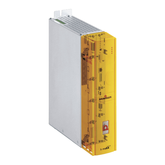
ESIGN AND PERATION A b maXX BM4000 device consists of power unit and controller part Power unit Controller part standard controller Design cover (standard controller only) Standard controller BM4XXX-XXX-XX1XX BM4XXX-XXX-XX2XX BM4XXX-XXX-XX3XX Controller part ES controller ES controller BM4XXX-XXX-XX4XX BM4XXX-XXX-XX5XX Figure 9: b maXX BM4000) The BM4-F-SIE-XX is designed as plug-in module for standard controller and can be re- placed or upgraded. -
Page 24: Function
Function Function The SSI encoder emulation sends on demand of a CNC control (Computer Numeric Con- trol) position data to this one. Transmission of the data takes place synchronously serial with a maximum data rate of 1.5 MBaud; the minimum data rate is 200 kBaud. A transmission cycle begins with the falling edge of the clock, generated by the CNC. - Page 25 Design and Operation m A transmission cycle is structured as follows: 1 The first falling clock edge determines the beginning of the transmission (clock is HIGH when not active). 2 The first rising clock edge defines the coding (data = low => binary, data = high => graycode). 3 With the next 12/12/16/20 rising clock edges the multi-turn information is transmitted.
-
Page 26: Bm-F-Sie-Xx For Standard Controller
BM-F-SIE-XX for standard controller BM-F-SIE-XX for standard controller The encoder module BM4-F-SIE-XX can be plugged in the standard controller of the b maXX 4000. The BM4-F-SIE-XX is connected to the controller part with a connector on the back side. On the front side is a 9-pole Sub-D connector (male). Connector (back side) Module name e.g. - Page 27 Design and Operation Possible combinations function modules/option modules Function modules Option modules Controller unit preferred slot Baumüller Nürnberg GmbH recommends, in order to reach the highest functional range, to insert the plug-in modules into these slots. possible slot only if the preferred slot is occupied, we recommend in order to reach the highest functional range, to insert the plug-in modules into this slot.
-
Page 28: Type Plate Bm4-F-Sie-Xx For Standard Controller
BM-F-SIE-XX for standard controller NOTE! EtherCAT option modules must not be plugged in slot J of a 3-rowed controller unit, because the module can be damaged. In case another BM4X-X-XXX plug-in module is plugged in an unsuitable slot, it will not operate. -
Page 29: Type Code Bm4-F-Sie-Xx For Standard Controller
Design and Operation 4.2.3 Type code BM4-F-SIE-XX for standard controller NOTE! This type code is valid for the encoder modules BM4-F-SIE-XX of series b maXX BM4000 exclusively. For other plug-in modules are different type codes available. Type code: - F - SIE - XX Device family, in which the plug-in module can be built in BM4 - - SIE - XX... -
Page 30: Sie-Xx In Es Controller
SIE-XX in ES controller SIE-XX in ES controller The SIE encoder emulation is mounted stationary in the ES controller. e.g. SIE-01 position B SIE-01 position B Figure 12: SSI encoder emulation in ES controller The controller is ordered with the desired function/option modules, these are mounted stationary (exception slot H) and cannot be changed. -
Page 31: Position Sie-Xx In The Es Controller
Design and Operation 4.3.1 Position SIE-XX in the ES controller Each position is clearly identified by a character. The SSI encoder emulation can be used at the following position. SIE-XX SIE-XX Controller Combinations function modules/option modules Function modules Option modules Controller unit with RS232- or Ethernet interface prefered slot Steckkarten_ES_Rev02_e... -
Page 32: Type Plate Sie-Xx In Es Controller
Display and operation elements NOTE! Only 2 analog outputs can be parametrized or linked even more than one AIO module is available. 4.3.2 Type plate SIE-XX in ES controller The type code of the SIE-XX is included in the type plate of the basic unit. 4.3.3 Type code SIE-XX in ES controller The type code has the form:... -
Page 33: Transport And Packaging
RANSPORT AND ACKAGING What to observe when transporting For initial transport the BM4-F-SIE-XX for standard controller is packed at the manufac- turer. If the device is to be further transported, ensure that the following conditions are met throughout the entire transport: m Climate class 2 K 3 as per EN 60721-3-2 m Temperature range - 25 °C up to + 70 °C m Vibration, shock, continuous shock class 2 M 1 as in EN 60721-3-2... -
Page 34: Unpacking
Unpacking Unpacking After having received the still packaged device: h Avoid transport shocks and hard jolts, e.g. when putting an item down. If no transport damage is visible: h Open the packaging of the device. h Verify the delivery scope based on the delivery note. File a claim with the responsible Baumüller representative if the delivery is incomplete. -
Page 35: Mounting
OUNTING In this chapter we describe the mechanical mounting of the plug-in module BM4-F-SIE-XX for BM4400, BM4600, BM4700 with standard controller. NOTE! The SSI encoder emulation is mounted stationary in the BM4400, BM4600, BM4700 with ES controller and cannot be changed, therefore no mounting is neces- sary! Preparation of mounting h Check the marking SIE-XX, wether the right plug-in module is available. -
Page 36: Assembly
Assembly Assembly WARNING! Danger as a result of faulty mounting! The mounting requires qualified personnel with adequate experience. Faulty mount- ing can lead to life-threatening situations or substantial material damage. Therefore: m Only allow mounting to be performed by employees of the manufacturer or by oth- er qualified personnel. - Page 37 Mounting 4 Turn the twist lock beyond and beneath by 90°. The twist locks now are standing horizontally. 5 Take the front panel cover towards the front off. Keep this cover. NOTICE! Note electrostatic discharge! The BM4-F-SIE-XX module contains ESD sensible parts. Therefore: m Regard the described ESD procedures when handling the plug-in module.
- Page 38 Assembly Instruction handbook b maXX (BM4-F-)SIE-XX (SSI enc. emulation) Document No.: 5.03056.02 Baumüller Nürnberg GmbH of 74...
-
Page 39: Installation
NSTALLATION In this chapter we describe the electrical installation of the SIE-XX or BM4-F-SIE-XX. The ZMounting– mechanical mounting is described in from page 35 and not necessary for BM4400, BM4600 and BM4700 with ES controller. Safety notes DANGER! Risk of fatal injury from electrical current! There is an immediate risk of fatal injury if live electrical parts are contacted. -
Page 40: Requirements For Electrical Connections
Requirements for electrical connections Requirements for electrical connections NOTICE! The danger is: Electricity. In case you do not ensure the requirements to the electrical connection of the SSI encoder emulation, it can be damaged/destroyed. m Ensure that the electrical power connection parameters as specified in the Tech- nical Data are adhered to and that the connections are made in accordance with the stipulated data. -
Page 41: Installation
Installation Installation 7.4.1 Pin assignment The Sub-D connector on the front of the SSI encoder emulation is assigned as follows: Pin No. Assignment Ground SSI encoder emulation not assigned not assigned not assigned not assigned not assigned not assigned not assigned not assigned DATA + DATA -... -
Page 42: Connection Cable
Installation 7.4.2 Connection cable Cable length The dependence of the maximum clock frequency to the cable length is shown in the diagram below: Figure 15: Cable length SSI encoder emulation The connection cable can be used for following: 1 Use the following materials: m Cable: data cable, paired drilled, Cu braiding, e.g. -
Page 43: Assignment Connection Cable Bm4-F-Sie-01 With Cnc Control
Installation m connect the cable shield with the housing of the Sub-D connector m connect the connector (15-pole) with the cable. CNC control Figure 16: Assignment connection cable BM4-F-SIE-01 with CNC control NOTE! The connection cable must be made according above mentioned construction guid- ZPin assignment–... -
Page 44: Installation Procedure
Installation 7.4.3 Installation procedure 1 Switch off the b maXX 4400 device and assure it against unintentional switching on during mounting. DANGER! Risk of fatal injury from electrical current! There is an immediate risk of fatal injury if live electrical parts are contacted. Therefore: m Switch off the current when any kind of work is being performed on the electrical system and ensure safety before switching on again. -
Page 45: Commissioning/Operation
OMMISSIONING PERATION This test-commissioning assures, that the SSI encoder emulation has been correctly recognized. Further information relating to commissioning and parameter settings of the encoder module can be found in parameter manual b maXX 4000 5.03039. Assure, that before commissioning the following preconditions are fulfilled: 1 The BM4-F-SIE-XX is correctly mounted (standard controller only). - Page 46 Safety notes NOTICE! Environmental conditions that do not meet the requirements. Environmental conditions that are non-compliant can lead to property damage. Therefore: m Ensure that the environmental conditions are kept compliant during operation (see instruction handbook b maXX 4000, operation conditions). WARNING! Risk of injury due to insufficient qualifications! Inevitably, when operating this electrical device, certain parts of this device are ener-...
-
Page 47: Procedure Of The Test-Commissioning
Commissioning/Operation Procedure of the test-commissioning The test-commissioning is divided into the following sections: 1 Recognition of SSI encoder emulation 2 Function test 8.2.1 Recognition of SSI encoder emulation During of the start of the device the controller automatically reads out the identification of the SSI encoder emulation. -
Page 48: Function Test
Procedure of the test-commissioning 4 Choose sub-menu „Service“ In this window is displayed whether the SSI encoder emulation is recognized in slot/ position C. Expectation Slot C: m Module type: SSI encoder emulation m Hardware version: dependent, e. g. „Version B“ m Software version SIE-01: >... -
Page 49: Parameter
Commissioning/Operation Parameter The parameter settings determine the behaviour of the SSI encoder emulation. The pa- rameters are set via ProDrive. 1 Start ProDrive. 2 Open Navigation. 3 Choose „SSI encoder emulation“ (path: device/Configuration/SSI encoder emulation). Figure 19: ProDrive Navigation All parameters can be set in window „SSI encoder emulation“. Figure 20: Settings SSI encoder emulation Instruction handbook b maXX (BM4-F-)SIE-XX (SSI enc. - Page 50 Parameter Instruction handbook b maXX (BM4-F-)SIE-XX (SSI enc. emulation) Document No.: 5.03056.02 Baumüller Nürnberg GmbH of 74...
-
Page 51: Maintenance
AINTENANCE Safety notes Basic information WARNING! Risk of injury due to improperly performed maintenance work! Improper maintenance can lead to severe personal injury and material damage. Therefore: m Before beginning work, make sure that there is enough space for mounting. m Make sure that the mounting area is kept clean and orderly. -
Page 52: Inspection Intervals - Maintenance Notes
Inspection intervals - maintenance notes Inspection intervals - maintenance notes Refer to Instruction handbook b maXX 4000, 5.12008. Repairs In case of device damage, please inform your sales office or: Baumüller Nürnberg GmbH Ostendstr. 80 - 90 90482 Nuremberg Germany Tel. -
Page 53: Troubleshooting And Fault Correction
ROUBLESHOOTING AND FAULT CORRECTION 10.1 Behavior in case of malfunctions Basic information DANGER! Risk of fatal injury from electrical current! Inevitably, when operating this electrical device, certain parts of it are energized with hazardous voltage. Therefore: m Pay heed to areas on the device that could be dangerous. WARNING! Risk of injury due to improper fault correction! Therefore:... -
Page 54: Fault Detection
10.2 Fault detection 10.2 Fault detection The fault can be caused by mechanical or electrical malfunctions. LED H4 The occurrence of an error state of a device b maXX 4000 is signalled by the lighting up of the red LED H4 on the front side of the housing. 7-segment display Additionally the error code is shown via the 7-segment display on the front side of the housing (not BM4XXX - XXX - XX0XX and BM4XXX - XXX - XX1XX). - Page 55 Troubleshooting and fault correction Operating Furthermore the error message is shown in the operating software: software ProDrive h Start the operating program ProDrive (from FW 3.07), if it isn’t running yet. NOTE! The controller software version and the operating software version must be compat- ible to use ProDrive with all functions.
-
Page 56: Drive Manager Prodrive
10.2 Fault detection h Select „Drive management“ The window „Drive manager“ opens, see below with an exemplary (error) message. Before the communication between controller and PC/laptop is started, the messages in in this list have been arranged in numerical order. The newly occurring messages are added to the end of the list, when communication is active. -
Page 57: 10.3 Error Handling
Troubleshooting and fault correction 10.3 Error handling The error messages in the system are built up hierarchically. An error message can result from a beneath in the hierarchic arranged error message. This is why the message „Error“ (level 1) can base on an error, which e. g. has appeared in „ModuleError“... -
Page 58: 10.3.1 Error Reset
10.3 Error handling 10.3.1 Error reset If the red error LED is lighting up, there is at least one error. There are several methods to reset errors: m Via ProDrive (from FW 3.07): Button “Quit errors” (either in the dialog box “Device manager” or on the page “Device manager“. -
Page 59: 10.3.2 Error Messages
Troubleshooting and fault correction 10.3.2 Error messages Figure 25: Survey error list The (error) messages are displayed in ProDrive window „Drive manager“. Instruction handbook b maXX (BM4-F-)SIE-XX (SSI enc. emulation) Document No.: 5.03056.02 of 74... - Page 60 10.3 Error handling 1st level 1st level errors are only interesting for the access to errors via parameters, to be used without ProDrive, e. g. at Field bus communication. This errors are not shown in ProDrive/ 7-segment display. Bit mapping see description of the parameter P0200 in the parameter manual. 2nd level Order of the error messages see survey (ZAbbildung 25–...
- Page 61 Troubleshooting and fault correction Error messages level 2 P0204 Error in function or option modules Error No. Meaning Reaction Troubleshooting ZError in function module A to E– Error in function module A 3rd level on page 63 error (= 3rd level) Error in function module B Error in function module C Error in function module D...
- Page 62 10.3 Error handling P0210 Error encoder manager Error No. Meaning Reaction Troubleshooting Absolute position of encoder 1 unknown pulse stop Use a different encoder If error occurs at sine incremental encoder, set P0150 bit 9 = 1 (error message „absolute position of encoder Absolute position of encoder 2 unknown pulse stop 1 unknown“...
- Page 63 Troubleshooting and fault correction Error messages level 3 NOTE! 3rd level errors are only displayed in ProDrive separated by a decimal point from the ZAbbildung 25– corresponding 2nd level error (refer to auf Seite 59). e.g.: Motor error 102: Group error find notch position (2nd level) Find notch position error 102.64: Drive moved more than 4 times delta angle.
- Page 64 10.3 Error handling Instruction handbook b maXX (BM4-F-)SIE-XX (SSI enc. emulation) Document No.: 5.03056.02 Baumüller Nürnberg GmbH of 74...
-
Page 65: Disposal
ISPOSAL NOTE! Baumüller products are not subject to the scope of application of the EU's Waste Electrical and Electronic Equipment Directive (WEEE, 2002/96/EC). Hence, Baumüller is not obligated to bear any costs for taking back and disposing of old de- vices. -
Page 66: Disposal Facilities/Authorities
11.2 Disposal facilities/authorities NOTICE! Avoid polluting the environment as a result of improper disposal. Therefore: m Only dispose in compliance with the health and safety regulations. m Take heed of any special local regulations. If you are unable to directly ensure safe disposal yourself, commission a suitable disposal contractor. -
Page 67: Appendixa - Declaration Of Conformity
A - D PPENDIX ECLARATION OF ONFORMITY Instruction handbook b maXX (BM4-F-)SIE-XX (SSI enc. emulation) Document No.: 5.03056.02 of 74... - Page 68 EC - Declaration of Conformity Doc.-No.: 5.14004.00 Date: 18-Mar-2014 according to EMC Directive 2004/108/EC and Low Voltage Directive 2006/95/EC The Manufacturer: Baumüller Nürnberg GmbH Ostendstraße 80-90 90482 Nürnberg, Germany declares, that the product: Designation: b maXX Type: Incremental encoder emulation for b maXX 4000 standard controller BM4-F-SIE-XX Manufactured since: 13-Dec-2004...
-
Page 69: Table Of Figures
Table of Figures Table of Figures Timing diagram 12/12 no parity ....................Timing diagram 12/12 parity ...................... Timing diagram 16/16 no parity....................Timing diagram 16/16 parity....................... Timing diagram 12/20 no parity....................Timing diagram 12/20 parity....................... Timing diagram 20/12 no parity....................Timing diagram 20/12 parity....................... - Page 70 Table of Figures Instruction handbook b maXX (BM4-F-)SIE-XX (SSI enc. emulation) Document No.: 5.03056.02 Baumüller Nürnberg GmbH of 74...
-
Page 71: Index
Index Accidents Inspection Assembly Inspection intervals Installation Installation procedure Caution Connecting cables Requirements Key to symbols Customer service LED H2 Danger LED H4 Danger areas Limitation of liability DC link discharge time 14, 65 Declaration of Conformity Maintenance Design cover Malfunctions, behavior Diagnosis Modifications... - Page 72 Index Safety equipment Spare parts Standard controller Storage Temperature range Technical data Transport Climatic class Temperature range Transport inspection TTL-rectangle pulse trains Twist lock Type code ES controller Type key Standard controller Type of plug-in module Type plate ES controller Standard controller Unpacking Use, compliant with indented purpose...
-
Page 73: Overview Of Revisions
Overview of Revisions Overview of Revisions Version Status Changes 5.02020.05 18-Nov--2013 Revision because of ES controller Instruction handbook b maXX (BM4-F-)SIE-XX (SSI enc. emulation) Document No.: 5.03056.02 of 74... -
Page 74: Document No.: 5.03056.02 Of
Notes: Instruction handbook b maXX (BM4-F-)SIE-XX (SSI enc. emulation) Document No.: 5.03056.02 Baumüller Nürnberg GmbH of 74... - Page 76 Baumüller Nürnberg GmbH Ostendstraße 80-90 90482 Nürnberg T: +49(0)911-5432-0 F: +49(0)911-5432-130 www.baumueller.de All information given in this manual is customer information, subject to change without notice. We reserve the right to futher develop and actualize our products continuously using our permanent revision service. Please notice, that specifications/data/information are current values according to the printing date. These statements are not legally binding according to the measurement, computation and calculations.
Need help?
Do you have a question about the b maXX BM4400 and is the answer not in the manual?
Questions and answers