Sign In
Upload
Manuals
Brands
Baumuller Manuals
DC Drives
b maxx BM4600
Baumuller b maxx BM4600 Manuals
Manuals and User Guides for Baumuller b maxx BM4600. We have
7
Baumuller b maxx BM4600 manuals available for free PDF download: Instruction Handbook Manual, Instruction, Compact Manual, Operating Handbook
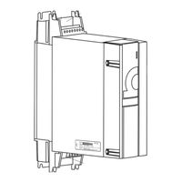
Baumuller b maxx BM4600 Instruction Handbook Manual (360 pages)
b maXX 4000 series
Brand:
Baumuller
| Category:
Power Tool
| Size: 13 MB
Table of Contents
Table of Contents
3
1 General
9
Information on the Instruction Handbook
9
Key to Symbols
10
Limitation of Liability
11
Copyright Protection
11
Other Applicable Documents
12
Spare Parts
12
Disposal
12
Guarantee Provisions
12
Customer Service
13
Terms Used
13
List of Other Applicable Documents
13
2 Safety
15
Contents of the Instruction Handbook
15
Changes and Modifications to the Device
15
Usage for the Intended Purpose
16
Responsibility of the Operating Company
17
Protective Devices
18
Training of the Personnel
19
Personal Protective Equipment
20
Special Hazards
21
Fire Fighting
22
Safety Equipment
23
Conduct in Case of Danger or Accidents
23
Signs and Labels
24
Signs and Labels BM4X1X
25
Signs and Labels BM4X3X/BM4X4X
26
Signs and Labels BM4X5X
27
Signs and Labels BM4X6X, BM4X7X
28
Type Code Labeling
29
3 Technical Data
31
Dimensions
31
Dimensions BM441X
32
Dimensions BM442X
33
Dimensions BM442X-S/A
33
Dimensions BM442X-F/C
34
Dimensions BM4X3X
35
Dimensions BM443X-S/Z, BM443X-A/F
35
Dimensions BM443X-C, BM463X-F
36
Dimensions BM4X4X
37
Dimensions BM444X-S/Z, BM464X-S/Z
37
Dimensions BM444X-A/F, BM464X-A/F
38
Dimensions BM4X5X
39
Dimensions BM445X-S/Z, BM465X-S/Z
39
Dimensions BM445X-A/F, BM465X-A/F
40
Dimensions BM465X-FXX-3XXXX and BM475X-FXX-3XXXX
41
Dimensions BM465X-FXX-3XXXX-RYY, BM475X-FXX-3XXXX-RYY
42
Dimensions BM465X-ZXX-3XXXX-[RYY], BM475X-ZXX-3XXXX-[RYY]
43
Dimensions BM4X6X
44
Dimensions BM446X-S/Z
44
Dimensions BM4X7X
48
Weight
50
Operating Requirements
51
System Types
51
Requirements to the Energy Supply / Supply System
52
Motor Requirements
54
Required Environmental Conditions
55
Correction Factors if the Operating Conditions Are Changed
56
Mounting Height
56
Environmental Temperature
57
Supply Voltage
57
Coherence between Rated Current and Peak Current
59
Calculation of the Thermal Rms Current
59
Coherence between Peak Current and Rated Current
59
Cooling
61
Electrical Data Basic Units
63
Electrical Data of the Universal Units
63
Electrical Data BM441X Universal Units
63
Electrical Data BM442X Universal Units
66
Electrical Data BM443X Universal Units
70
Electrical Data BM444X Universal Units
73
Electrical Data BM445X Universal Units
76
Electrical Data BM446X Universal Units
79
Electrical Data BM4X7X Universal Units
82
Electrical Data BM46XX Acceleration Units
84
Electrical Data BM4632 Acceleration Units
85
Electrical Data BM464X Acceleration Units
87
Electrical Data BM465X Acceleration Units
89
Electrical Data BM466X Acceleration Units
91
Electrical Data BM47XX Continuous Current Units
93
Electrical Data Power Modules
96
Electrical Data BM442X Power Modules
96
Electrical Data BM443X Power Modules
98
Electrical Data BM444X Power Modules
100
Electrical Data BM445X Power Modules
102
Electrical Data BM446X Power Module
104
Additional Data Referring to Water-Cooled Brake Resistors
106
Output Frequency Dependent Continuous Current Derating BM4XXX
112
Output Frequency Dependent Maximum Current Derating BM46XX
113
Overload Monitoring Modes
114
4 Design and Operation
115
Functioning
116
Controller
117
Standard Controller
118
ES Controller
121
Encoder Modules Slot/Position a and B
123
Interconnect Devices
124
MIX Mode BM443X Generation 1 and 2
124
Type Plate
125
Type Code
126
Explanation Type Code
126
Explanation Version Code
130
UL Notes
131
Display and Operation Elements
132
Leds
132
7-Segment Display
135
Address Switch S1 - S4 (Only es Controller)
136
5 Transport and Packaging
141
Safety Notes for Transport
141
What to Observe When Transporting
141
Transport Inspection
142
Unpacking
142
Disposal of the Packaging
142
6 Mounting
143
Safety Notes
143
Preparing for Mounting
146
Drilling Patterns
147
Drilling Patterns BM441X
147
Drilling Patterns BM442X
148
Drilling Patterns BM4X3X
148
Drilling Patterns BM4X4X
149
Drilling Patterns BM4X5X
150
Drilling Patterns BM4X6X
151
Drilling Patterns BM4X7X
153
Mounting Instructions
155
Requirements Mounting Plate for Cold Plate
162
Connecting the Water Cooler
162
7 Installation
163
Safety Notes
163
Voltage Test
165
Demands on the Power Supply
166
Connection Instructions at Special Power Supply Systems
167
Requirements to the Connecting Cables
168
Protection of the Device and the Cable
168
PE Connection and RCD Compatibility
169
Installation Requirements with Regard to EMC
169
Requirements for the Motor Temperature Sensors
170
Installation Procedure
171
Wiring Diagrams
173
Connection Diagrams
173
BM44XX, BM46XX, BM47XX (Basic Units)
173
BM44XX, BM46XX, BM47XX Power Module
176
Terminal Overviews
180
Terminals BM4412, BM4413
181
Terminals BM4414
182
Terminals BM442X
183
Terminals BM443X, BM463X
184
Terminals BM444X, BM464X
185
Terminals BM445X, BM446X, BM465X, BM466X
186
Terminals BM466X, BM476X
187
Terminals BM4755
188
Terminals BM447X, BM4773
189
Electrical Connection Power Unit
191
Requirements for the Screwing
194
Controller Terminals
195
Encoder Connection Slot/Position a and B
203
Analog Input Slot/Position D and E
218
Digital Inputs Slot a to E/Position D
220
8 Operation
223
Safety Notes
223
Operating Concept
224
Enable Signals
224
Power on Switching Frequency / DC Link Charging
225
Power Supply Switch-On Frequency BM441X and BM442X
225
Power Supply Switch-On Frequency BM443X (Generation 1)
225
Power Supply Switch-On Frequency BM443X Generation 2, BM4X4X to BM4X7X
226
Calculation of the Maximum Permitted External Capacity
227
Effects of the Different Charging Circuits
228
Table of Charging Times
228
9 Troubleshooting and Fault Correction
229
Behavior in Case of Malfunctions
229
Monitoring Functions
230
Fault Detection
234
Error Handling
238
Error Reset
239
Error Parameters, Error Messages, Error Reactions
240
Error Messages (2Nd Level)
241
Sub-Error Messages (3Rd Level)
250
Warnings
258
10 Maintenance
261
Safety Notes
261
Environmental Condition
262
Inspection Intervals - Maintenance Notes
262
Periodic Maintenance
264
Repairs
266
11 Accessories and Spare Parts
267
Cabling
268
Cables Power Supply-Device
268
Cables Device-Motor
270
Cable Control Voltage Supply/Signals
271
Interface Cable RS232
272
Fuses
273
Fuses BM441X
275
Fuses BM442X
277
Fuses BM4X3X
280
Fuses BM4X4X
281
Fuses BM4X5X
284
Fuses BM4X6X
288
Fuses BM447X
292
UL Fuse in the Ballast Circuit
293
Extra-Low Voltage Protection
293
Mains Filters
294
Block Diagram of Filter for Mains Applications (Simplified)
294
Baumüller Mains Filter Type Code
294
Required Mains Filter Environmental Conditions
294
Electrical Data Mains Filter
295
Mains Filter Selection
298
Power Chokes
300
Baumüller Accessories
304
Shielding Clamp
304
Cable RS232
304
Accessories Ethernet/Ethercat
305
Accessories - Canopen
306
Encoder Cables
307
Design Cover and Connectors
312
12 Shutdown, Storage
313
Safety Instructions
313
Requirements to the Executing Personnel
314
Shutdown
314
Demounting
314
Storage Conditions
315
Recommissioning
316
13 Disposal
317
Safety Notes
317
Disposal Facilities/Authorities
319
Appenidx a - Abbreviations
321
Appenidx B - Declaration of Conformity
323
Declaration of Conformity
323
B.1 Declaration of Conformity
323
Appenidx C - Safe Stop
327
Methods to Avoid an Unexpected Starting
327
Safe Torque off (STO)
330
Safety Classifications and Safety Notes
330
Function Principle STO
333
Shutdown Paths
334
C.2.2.1 Shutdown Paths
334
Sequence Diagram
335
C.2.2.2 Sequence Diagram
335
Connection Diagrams
338
C.2.2.3 Connection Diagrams
338
Safe Stop
340
Safety Categories According to en ISO 13849-1
340
C.3 Safe Stop
340
The Safety Relay
341
Application Example for Machine of Category
342
Application Example for Machine of Category
344
Application Expansions
346
C.3.5 Application Expansions
346
Requirements on an OSSD Test Pulse
349
Technical Data Safety Relay Module
350
Table of Figures Table of Figures
353
Table of Figures
353
Index
355
Overview of Revisions
357
Document No.: 5.12008.07 of
358
Advertisement
Baumuller b maxx BM4600 Instruction (104 pages)
Encoder module
Brand:
Baumuller
| Category:
Media Converter
| Size: 4 MB
Table of Contents
Table of Contents
3
BM4-F-ENC-XX for Standard Controller
3
1 General
5
Information on this Instruction Handbook
5
Key to Symbols
6
Limitation of Liability
7
Copyright Protection
7
Other Applicable Documents
8
Spare Parts
8
Disposal
8
Guarantee Provisions
8
Customer Service
8
1.10 Used Terms
9
1.11 List of Associated Documentations
9
2 Safety
11
Contents of the Instruction Handbook
11
Changes and Modifications to the Device
11
Use, Compliant with Intended Purpose
12
Responsibility of the Operating Company
12
Training of the Personnel
13
Special Hazards
14
Fire Fighting
15
Safety Equipment
16
Behavior in Hazardous Situations or at Accidents
16
2.10 Signs and Labels
17
3 Technical Data
19
Operation Conditions
19
Current Consumption of Encoder Modules
20
Information Regarding Maximum Speed
21
Specification of Encoder Modules
22
4 Design and Operation
27
B Maxx BM4000)
27
Function
28
BM4-F-ENC-XX for Standard Controller
30
Slots BM4-F-ENC-XX for Standard Controller
30
Encoder Module for Standard Controller
30
Type Plate BM4-F-ENC-XX for Standard Controller
32
Type Code BM4-F-ENC-XX for Standard Controller
33
Danger Areas BM4-F-ENC-XX for Standard Controller
33
ENC-XX in es Controller
34
ENC-XX in the es Controller
34
Position ENC-XX in the es Controller
35
Type Plate ENC-XX in es Controller
36
Type Code ENC-XX in es Controller
36
Display and Operation Elements
37
5 Transport and Packaging
39
What to Observe When Transporting
39
Transport Inspection
39
Unpacking
40
Disposal of the Packaging
40
6 Mounting
41
Preparation of Mounting
41
Assembly
42
7 Installation
45
Safety Notes
45
Requirements on the Electrical Connection
46
Connection Diagrams
47
Connection BM4-F-ENC-XX Standard Controller
47
Connection Diagram BM4-F-ENC-XX Standard Controller
47
Connection ENC-XX es Controller
48
Connection Diagram ENC-XX es Controller
48
Pin Assignment
49
Construction Guidance Connection Cables
59
Connection Cable for (BM4-F-)ENC-05
60
Connection Cable BM4-F-ENC-07
61
Connection Cable (BM4-F-)ENC-17
62
Connection Cable (BM4-F-)ENC-27
63
Connection Cable (BM4-F-)ENC-08
64
Installation Procedure
65
8 Commissioning/Operation
67
Safety Notes
67
Procedure of the Test-Commissioning
69
Recognition of the Encoder Module
69
Prodrive Navigation
69
Prodrive Start Screen
70
Further Information on Parameterization
71
Function Test
71
Parameter for Configuration
71
9 Maintenance
73
Safety Notes
73
Environmental Condition
73
Inspection Intervals - Maintenance Notes
74
Repairs
74
10 Troubleshooting and Fault Correction
75
Behavior in Case of Malfunctions
75
Fault Detection
76
Error Messages 7-Segment Display
76
Drive Manager Prodrive
78
10.3 Error Handling
79
10.3.1 Error Reset
80
Prodrive Drive Manager
80
10.3.2 Error Messages
81
Survey Error List
81
11 Accessories and Spare Parts
89
Motor-Side Encoder Connector
89
Connection Cable
90
12 Disposal
93
12.1 Safety Notes
93
Disposal Facilities/Authorities
94
Appendixa - Declaration of Conformity
95
Table of Figures Table of Figures
97
Appendix A - Declaration of Conformity
97
Table of Figures
97
Index
99
Overview of Revisions
101
Baumuller b maxx BM4600 Instruction Handbook Manual (84 pages)
Analog IO module
Brand:
Baumuller
| Category:
Control Unit
| Size: 3 MB
Table of Contents
Table of Contents
3
1 General
5
Information on this Instruction Handbook
5
Key to Symbols
6
Limitation of Liability
7
Copyright Protection
7
Other Applicable Documents
8
Spare Parts
8
Disposal
8
Guarantee Provisions
8
Customer Service
8
1.10 Used Terms
9
1.11 List of Associated Documentations
9
2 Safety
11
Contents of the Instruction Handbook
11
Changes and Modifications to the Device
11
Use, Compliant with Intended Purpose
12
Responsibility of the Operating Company
12
Training of the Personnel
13
Special Hazards
14
Fire Fighting
15
Safety Equipment
16
Behavior in Hazardous Situations or at Accidents
16
2.10 Signs and Labels
17
3 Technical Data
19
Electrical Data
19
Power Input
20
Input Linearity Error
20
Operation Conditions
20
4 Design and Operation
21
B Maxx BM4000)
21
Function
22
BM-F-AIO-XX for Standard Controller
23
Slots BM4-F-AIO-XX for Standard Controller
23
Analog IO Module for Standard Controller
23
Type Plate BM4-F-AIO-XX for Standard Controller
25
Type Code BM4-F-AIO-XX for Standard Controller
26
Danger Areas BM4-F-AIO-XX for Standard Controller
26
AIO-XX in es Controller
27
AIO-XX for es Controller
27
Position AIO-XX in es Controller
28
Type Plate AIO-XX in es Controller
29
Type Code AIO-XX in es Controller
29
Display and Operation Elements
29
5 Transport and Packaging
31
What to Observe When Transporting
31
Transport Inspection
31
Unpacking
32
Disposal of the Packaging
32
6 Mounting
33
Preparation of Mounting
33
BM4-F-AIO-XX for Standard Controller
33
Assembly
34
7 Installation
37
Safety Notes
37
Requirements on the Electrical Connection
38
Requirements for the Connection Cables
38
Connection Diagrams
39
Connection Diagram Analog IO Module
39
Installation Procedure
40
Internal Circuit Diagram
41
Internal Circuit Diagram of Analog-IO-Modules (BM4-F-)AIO-01/-02/-03
41
Internal Circuit of Analog IO Module (BM4-F-)AIO-01/-02/-03
41
Internal Circuit Diagram of Analog IO Module (BM4-F-)AIO-04
42
8 Commissioning/Operation
43
Safety Notes
43
Procedure of the Commissioning
44
Recognition of the Analog IO Module
44
Prodrive Navigation
45
Prodrive Service
46
Prodrive Navigation, Submenu „IO Analog Inputs
47
Analog Input Link
48
Module Not Existent
48
Testing of the Analog IO Module
49
Testing of Inputs AIO-01, -02 and -03
50
Input Selection AIO-01, -02 and -03
50
Testing of Inputs AIO-04
51
Analog Input Link 1, AIO-04
51
Input Selection AIO-04
52
8.2.2.3 Testing of Outputs
53
Analog Output Link
53
Menu Analog Output Link
53
Output Selection
54
Offset Adjustment of an Analog Input Channel
55
Offset Adjustment of AIO-01, -02, -03
55
Offset Adjustment AIO-04
57
Operation
58
Configuration, Parameter List
59
9 Maintenance
61
Safety Notes
61
Environmental Condition
61
Inspection Intervals - Maintenance Notes
62
Repairs
62
10 Troubleshooting and Fault Correction
63
Behavior in Case of Malfunctions
63
Fault Detection
64
Error Messages 7-Segment Display
64
Drive Manager Prodrive
66
10.3 Error Handling
67
10.3.1 Error Reset
68
Prodrive Drive Manager
68
10.3.2 Error Messages
69
Survey Error List
69
11 Disposal
73
11.1 Safety Notes
73
Disposal Facilities/Authorities
74
Appendixa - Declaration of Conformity
75
Table of Figures Table of Figures
77
Appendix A - Declaration of Conformity
77
Table of Figures
77
Index
79
Overview of Revisions
81
Advertisement
Baumuller b maxx BM4600 Instruction Handbook Manual (76 pages)
BM4-F-SIE-XX, SIE-XX SSI encoder emulation
Brand:
Baumuller
| Category:
Media Converter
| Size: 3 MB
Table of Contents
Table of Contents
3
Mounting
3
Type Plate BM4-F-SIE-XX for Standard Controller
3
1 General
5
Information on this Instruction Handbook
5
Key to Symbols
6
Limitation of Liability
7
Copyright Protection
7
Other Applicable Documents
8
Spare Parts
8
Disposal
8
Guarantee Provisions
8
Customer Service
8
1.10 Used Terms
9
1.11 List of Associated Documentations
9
2 Safety
11
Contents of the Instruction Handbook
11
Changes and Modifications to the Device
11
Use, Compliant with Intended Purpose
12
Responsibility of the Operating Company
12
Training of the Personnel
13
Special Hazards
14
Fire Fighting
15
Safety Equipment
16
Behavior in Hazardous Situations or at Accidents
16
2.10 Signs and Labels
17
3 Technical Data
19
Operation Conditions
19
Timing Diagrams of Data Transmission
20
Timing Diagram 12/12 no Parity
20
Timing Diagram 12/12 Parity
20
Timing Diagram 16/16 no Parity
20
Timing Diagram 16/16 Parity
20
Timing Diagram 12/20 no Parity
20
Electrical Data
21
Timing Diagram 12/20 Parity
21
Timing Diagram 20/12 no Parity
21
Timing Diagram 20/12 Parity
21
4 Design and Operation
23
Function
24
BM-F-SIE-XX for Standard Controller
26
Slots BM4-F-SIE-XX for Standard Controller
26
BM4-F-SIE-XX for Standard Controller
26
Type Plate BM4-F-SIE-XX for Standard Controller
28
Type Code BM4-F-SIE-XX for Standard Controller
29
Danger Areas BM4-F-SIE-XX for Standard Controller
29
SIE-XX in es Controller
30
SSI Encoder Emulation in es Controller
30
Position SIE-XX in the es Controller
31
Type Plate SIE-XX in es Controller
32
Type Code SIE-XX in es Controller
32
Display and Operation Elements
32
5 Transport and Packaging
33
What to Observe When Transporting
33
Transport Inspection
33
Unpacking
34
Disposal of the Packaging
34
6 Mounting
35
Preparation of Mounting
35
BM4-F-SSI-XX for Standard Controller
35
Assembly
36
7 Installation
39
Safety Notes
39
Requirements for Electrical Connections
40
Requirements for the Connection Cables
40
Installation
41
Pin Assignment
41
Connection Cable
42
Cable Length SSI Encoder Emulation
42
Assignment Connection Cable BM4-F-SIE-01 with CNC Control
43
Installation Procedure
44
8 Commissioning/Operation
45
Safety Notes
45
Procedure of the Test-Commissioning
47
Recognition of SSI Encoder Emulation
47
Prodrive Navigation
47
Function Test
48
Prodrive Service
48
Parameter
49
Settings SSI Encoder Emulation
49
9 Maintenance
51
Safety Notes
51
Environmental Condition
51
B Maxx BM4000
51
Inspection Intervals - Maintenance Notes
52
Repairs
52
10 Troubleshooting and Fault Correction
53
Behavior in Case of Malfunctions
53
Fault Detection
54
Error Messages 7-Segment Display
54
Drive Manager Prodrive
56
10.3 Error Handling
57
10.3.1 Error Reset
58
10.3.2 Error Messages
59
11 Disposal
65
11.1 Safety Notes
65
Disposal Facilities/Authorities
66
Appendixa - Declaration of Conformity
67
Table of Figures Table of Figures
69
Appendix A - Declaration of Conformity
69
Table of Figures
69
Index
71
Overview of Revisions
73
Document No.: 5.03056.02 of
74
Baumuller b maxx BM4600 Instruction Handbook Manual (76 pages)
Digital IO module
Brand:
Baumuller
| Category:
Control Unit
| Size: 2 MB
Table of Contents
Table of Contents
3
1 General
5
Information on this Instruction Handbook
5
Key to Symbols
6
Limitation of Liability
7
Copyright Protection
7
Other Applicable Documents
8
Spare Parts
8
Disposal
8
Guarantee Provisions
8
Customer Service
8
1.10 Used Terms
9
1.11 List of Associated Documentations
9
2 Safety
11
Contents of the Instruction Handbook
11
Changes and Modifications to the Device
11
Use, Compliant with Intended Purpose
12
Responsibility of the Operating Company
12
Training of the Personnel
13
Special Hazards
14
Fire Fighting
15
Safety Equipment
16
Behavior in Hazardous Situations or at Accidents
16
2.10 Signs and Labels
17
3 Technical Data
19
Electrical Data
19
Operation Conditions
20
4 Design and Operation
21
B Maxx BM4000)
21
Function
22
BM-F-DIO/FIO-XX for Standard Controller
23
Slots BM4-F-DIO/FIO-XX for Standard Controller
23
Digital IO Module for Standard Controller
23
Type Plate BM4-F-DIO/FIO-XX for Standard Controller
25
Type Code BM4-F-DIO/FIO-XX for Standard Controller
26
Danger Areas BM4-F-DIO/FIO-XX for Standard Controller
26
DIO/FIO-XX in es Controller
27
Position DIO/FIO-XX in es Controller
28
Type Plate DIO/FIO-XX in es Controller
29
Type Code DIO/FIO-XX in es Controller
29
Display and Operation Elements
29
5 Transport and Packaging
31
What to Observe When Transporting
31
Transport Inspection
31
Unpacking
32
Disposal of the Packaging
32
6 Mounting
33
Preparation of Mounting
33
BM4-F-DIO/FIO-XX for Standard Controller
33
Assembly
34
7 Installation
37
Safety Notes
37
Requirements on the Electrical Connection
38
Requirements for the Connection Cables
38
Remove Insulation
38
Connection Diagrams
39
Connection Diagram Digital IO Module
39
Installation Procedure
41
Internal Circuit Diagram Digital IO Module
42
Internal Circuit of Digital IO Module
42
8 Commissioning/Operation
43
Safety Notes
43
Procedure of the Commissioning
44
Recognition of the Digital IO Module
44
Prodrive Navigation
45
Prodrive Service
46
Prodrive Navigation, Submenu „IO Digital Inputs
47
Selection „Input
47
Module Not Existent
48
Testing of the Digital IO Module
49
Menu „Digital Input Link
49
Menu „Digital Output Link
51
9 Maintenance
53
Safety Notes
53
Environmental Condition
53
Inspection Intervals - Maintenance Notes
54
Repairs
54
10 Troubleshooting and Fault Correction
55
Behavior in Case of Malfunctions
55
Fault Detection
56
Error Messages 7-Segment Display
56
Drive Manager Prodrive
58
10.3 Error Handling
59
10.3.1 Error Reset
60
Prodrive Drive Manager
60
10.3.2 Error Messages
61
Survey Error List
61
11 Disposal
65
11.1 Safety Notes
65
Disposal Facilities/Authorities
66
Appendixa - Declaration of Conformity
67
Table of Figures Table of Figures
69
Appendix A - Declaration of Conformity
69
Table of Figures
69
Index
71
Overview of Revisions
73
Baumuller b maxx BM4600 Compact Manual (96 pages)
Brand:
Baumuller
| Category:
DC Drives
| Size: 4 MB
Table of Contents
Table of Contents
3
1 Introduction
5
Copyright and Trade Mark
5
2 Fundamental Safety Instructions
7
Legal Information
7
3 Description of the Devices
9
Marking of the Device - Type Key
9
Position of Type Key Label
9
4 Mounting
13
Mounting Instruction BM441X, BM442X-S, BM443X-S/Z, BM463X-S/Z, BM444X-S/Z, BM464X-S/Z
14
Mounting Instruction BM445X-S/Z, BM465X-S/Z, BM446X-S/Z and BM466X-S/Z
15
Mounting Instruction BM447X-A/F and BM477X-FXX-3XXXX
16
Mounting Instruction 'Miscellaneous
17
5 Installation
19
Connection Diagram
20
Connection Diagram with a Directly Controlled Motor Brake
20
Connection Diagram with Motor Brake Controlled Via an Additional Relay
21
Connection Fan BM447X-A
22
Connection Diagrams
23
Electrical Connections for Mains, Motor, Upon Others for BM4412 and BM4413
23
Electrical Connections for Mains, Motor, Upon Others for BM4414
24
Electrical Connections for Mains, Motor, Upon Others for BM442X
25
Electrical Connections for Mains, Motor, Upon Others for BM443X and BM463X
26
Electrical Connections for Mains, Motor, Upon Others for BM444X and BM464X *) Only BM444X-S/-A
27
Electrical Connections for Mains, Motor, Upon Others for BM445X, BM465X,BM446X and BM466X *) Only BM445X-S/-A and BM446X-S/-A
28
Electrical Connections for Mains, Motor, Upon Others for BM466X and BM476X
29
Electrical Connections for Mains, Motor, Upon Others for BM4755
30
Electrical Connections for Mains, Motor, Upon Others for BM447X and BM4773 *)Only BM447X-/-A
31
Connection X100 and Connections of the Controller Unit
32
6 Commissioning
33
Requirements to the Executing Personnel
33
Preconditions
34
Preparations
34
Prodrive: Start Window
37
Prodrive: Version Conflict
38
Prodrive: Select Device
39
Prodrive: Startpage
40
Prodrive: Navigation
40
Survey
42
Executing Commissioning
43
Prodrive: Drive Manager
45
Prodrive: Power Unit
46
Prodrive: Encoder 1 Configuration
48
Prodrive: Motor Database
49
Prodrive: Selection of the Motor
49
Prodrive: Motor
51
Prodrive: Parameter List
52
Prodrive: Data Set Management
52
Prodrive: Find Notch Position: Drive Manager
54
Prodrive: Ramp Function Generator
55
7 Operation
59
Enable Signals
59
Switch-On Frequency
59
Display Elements - LED
60
Operating Condition (H1, H2)
60
Current Limit (H3)
61
Error (H4)
61
Display
61
8 Error Detection and Troubleshooting
63
Error Detection
63
Troubleshooting
63
Reset Errors
64
Error Parameters - Error Messages (Error List) - Error Reactions
64
Parameter Description - Warnings (Warning Bit List)
87
Table of Figures Table of Figures
89
Table of Figures
89
Index
91
Revision Survey
93
Document No.: 5.06014.02 of
94
Baumuller b maxx BM4600 Operating Handbook (82 pages)
For PowerLink BM4-O-PLK-01
Brand:
Baumuller
| Category:
Controller
| Size: 1 MB
Table of Contents
Table of Contents
3
1 Introduction
5
General Information
5
Content of Instruction Manual to POWERLINK Controlled Node
5
Mounting and Installation
6
Address Setting
6
XDD File
6
2 Fundamental Safety Instructions
7
Safety Notes and Mandatories
7
Information Sign
7
3 Basics POWERLINK
9
Literature Concerning POWERLINK
9
Basic Principles POWERLINK
10
Supported Operation Modes of the Canopen Device Profile DSP402
13
Short Summery
13
Operating Modes and Field Bus Objects
14
4 Communication to the B Maxx 4000 Controller
17
Communication Flow
17
Parameterizing the BACI Communication Times
18
Configuration Possibilities of the POWERLINK Controlled Node in Prodrive
19
Changing the Units of some Fieldbus Objects
19
Canopen Offset
19
BACI Communication Settings
19
Standardization of Speed 100% / 200
19
Gear Factor
20
Factor Group According to Cia ® 402
20
Calculation on the Basis of the Factor Group
21
General Notes According POWERLINK Controlled Node
22
User Units UU
23
Canopen Offset
24
Homing Necessary for Positioning
24
Types of Positioning, Depending on the Positioning Mode (P0601)
25
5 Data Exchange and Parameterization
27
Directory of Objects for Communication Control
28
Net Work Management (NMT)
31
State Diagram POWERLINK Controlled Node
31
Service Data (SDO)
32
Frame Structure Soa
33
Frame Structure Asnd
34
Error Reactions
34
Synchronization (SYNC)
36
Frame Structure Soc
36
Process Data (PDO)
37
Frame Structure Preq and Pres
37
PDO Mapping
38
6 Configuration Example with B&R X20 PLC
41
Configuration - Import Fieldbus Device
41
Configuration - Physical View - Open POWERLINK
42
Configuration - Select Controller Module
43
Configuration - Option Module in Physical View
43
Appendixa - Abbreviations
45
Appendix A - Abbreviations
47
Appendix B - Quick Reference
47
4000 Object Numbers (Manufacturer-Specific Objects)
47
6000 Object Numbers (Device Profile DSP 402)
48
Appendix C - Conversion Tables
53
Appendix D - Technical Data: POWERLINK Controlled Node
73
Technical Features
73
Data Channels to the B Maxx 4000 Controller
73
D.1 Technical Features
73
Table of Figures
75
Index
77
Revision Survey
79
Document No. 5.13013.04 of
80
Advertisement
Related Products
Baumuller b maxx BM4400
Baumuller b maxx BM4700
Baumuller b maXX BM1000
Baumuller BM5-SSL
Baumuller b maXX BM4600 ES
Baumuller b maXX BM4 Series
Baumuller BM4-F-AIO Series
Baumuller BM4-F-AIO-04
Baumuller BM4145
Baumuller BM4-F-SEA
Baumuller Categories
Control Unit
Engine
Controller
Media Converter
Servo Drives
More Baumuller Manuals
Login
Sign In
OR
Sign in with Facebook
Sign in with Google
Upload manual
Upload from disk
Upload from URL