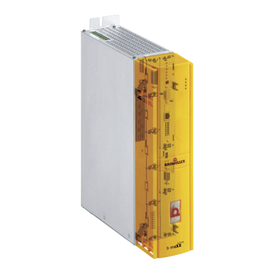
Baumuller b maxx BM4400 Compact Manual
Hide thumbs
Also See for b maxx BM4400:
- Instruction handbook manual (360 pages) ,
- Manual (250 pages) ,
- Instruction (104 pages)
Chapters
Table of Contents

Related Manuals for Baumuller b maxx BM4400


Summary of Contents for Baumuller b maxx BM4400
- Page 1 Compact manual English Language Translation Document No. 5.06014.02 Part No. 397361 Status 24.05.2011 ® b maXX BM4400, BM4600, POWER CONVERSION EQUIPMENT BM4700 LISTED 38WA Read the manual before starting any work! 5.06014.02...
- Page 2 Title Compact manual ® Product b maXX BM4400, BM4600, BM4700 Version 5.06014.02 Article number 397361 Status 24.05.2011 Copyright These instructions may be copied by the owner in any quantity but only for internal use. For other purposes these operating instructions and extracts thereof must not be copied or reproduced.
-
Page 3: Table Of Contents
Table of contents Introduction ............. . Copyright and trade mark . - Page 4 Table of contents ® Compact manual b maXX BM4400, BM4600, BM4700 Document no.: 5.06014.02 Baumüller Nürnberg GmbH of 94...
-
Page 5: Introduction
NTRODUCTION This short instruction serves as an assistance for the mounting of the devices of the series ® b maXX BM4400, BM4600, BM4700 with the type designation BM44XX - XXX - XX2XX[Ryy] in a switching cabinet. ® Please, take all information for system configuration with b maXX BM4400, BM4600, ®... - Page 6 Copyright and trade mark ® Compact manual b maXX BM4400, BM4600, BM4700 Document no.: 5.06014.02 Baumüller Nürnberg GmbH of 94...
-
Page 7: Fundamental Safety Instructions
UNDAMENTAL SAFETY INSTRUCTIONS Legal information This manual is addressed to technical qualified personnel, who is specifically skilled and who is thoroughly familiar with all warnings and maintenance procedures. The user is responsible for the execution of service and commissioning according to the safety notes of the prevailing standards and other relevant national and local instructions concerning conductor dimensioning and protection, grounding, disconnector, overcurrent protection and so on. - Page 8 Legal information ® Compact manual b maXX BM4400, BM4600, BM4700 Document no.: 5.06014.02 Baumüller Nürnberg GmbH of 94...
-
Page 9: Description Of The Devices
ESCRIPTION OF THE DEVICES Marking of the device - type key On the type plate (label) you will find, besides others, the type key of the device. Figure 1: Position of type key label ® Compact manual b maXX BM4400, BM4600, BM4700 Document no.: 5.06014.02 of 94... - Page 10 Marking of the device - type key The type key has the form: BM4XXX - XXX - XXXXX[Ryy] - XX. Directly behind the type key is the design code (-XXXX - X - XXX - XXX). The design code contains information, which only is important to Baumüller Nürnberg GmbH.
- Page 11 Description of the devices BM4XXX - XXX - XXXXX[Ryy] - XX Optional chopper resistor R16: Chopper resistor with 16 Ω R10: Chopper resistor with 10 Ω R05: Chopper resistor with 5 Ω R03: Chopper resistor with 3 Ω BM4XXX - XXX - XXXXX[Ryy] - XX State of software controller (firmware) 01: Series version 1.x 03: Series version 3.x...
- Page 12 Marking of the device - type key ® Compact manual b maXX BM4400, BM4600, BM4700 Document no.: 5.06014.02 Baumüller Nürnberg GmbH of 94...
-
Page 13: Mounting
OUNTING The installation instructions, dimensions and drilling plans of the individual device ver- sions for the configuration are to be taken from the manual. ® Compact manual b maXX BM4400, BM4600, BM4700 Document no.: 5.06014.02 of 94... -
Page 14: Mounting Instruction Bm441X, Bm442X-S, Bm443X-S/Z, Bm463X-S/Z, Bm444X-S/Z, Bm464X-S/Z
Figure 2: Mounting instruction BM441X, BM442X-S, BM443X-S/Z, BM463X-S/Z, BM444X-S/Z, BM464X-S/Z Device BM441X-XXX BM441X-XXX BM442X-S BM443X-S/Z BM444X-S/Z BM463X-S/Z BM464X-S/Z A - screws 2 x M5 4 x M5 4 x M5 4 x M5 4 x M5 B - washers 2 x (5.3 x 10) 4 x (5.3 x 10) 4 x (5.3 x 10) 4 x (5.3 x 10) -
Page 15: Mounting Instruction Bm445X-S/Z, Bm465X-S/Z, Bm446X-S/Z And Bm466X-S/Z
Mounting Figure 3: Mounting instruction BM445X-S/Z, BM465X-S/Z, BM446X-S/Z and BM466X-S/Z Device BM445X-S/Z BM446X-S/Z BM465X-S/Z BM466X-S/Z A - screws 4 x M8 4 x M8 B - washers 4 x (8.4 x 17) 4 x (8.4 x 17) C - mount spacing c = 7 mm c = 7 mm ®... -
Page 16: Mounting Instruction Bm447X-A/F And Bm477X-Fxx-3Xxxx
Figure 4: Mounting instruction BM447X-A/F and BM477X-FXX-3XXXX Device BM447X-S/A BM447X-F BM477X-FXX-3XXXX A - screws 38 x M6 22 x M6 B - conical spring washers 38 x DIN6796-6-FST 22 x DIN6796-6-FST C - washers 38 x (6.4 x 12.5) 22 x (6.4 x 12.5) ®... -
Page 17: Mounting Instruction 'Miscellaneous
Mounting Figure 5: Mounting instruction ’miscellaneous’ Device BM454X-A/F/Z/C BM443X-A/F/C BM444X-A/F BM445X-A/F BM446X-A/F BM463X-A/F BM464X-A/F BM465X-A/F BM466X-A/F A - screws 4 x M5 14 x M4 16 x M5 16 x M8 20 x M8 B - washers 4 x (5.3 x 10) 14 x (4.3 x 9) 16 x (5.3 x 15) 16 x (8.4 x 17) 20 x (8.4 x 17) - Page 18 ® Compact manual b maXX BM4400, BM4600, BM4700 Document no.: 5.06014.02 Baumüller Nürnberg GmbH of 94...
-
Page 19: Installation
NSTALLATION The important data for the dimensioning of the electric connections are to be found in the manual. ® Compact manual b maXX BM4400, BM4600, BM4700 Document no.: 5.06014.02 of 94... -
Page 20: Connection Diagram
Connection diagram Connection diagram Figure 6: Connection diagram with a directly controlled motor brake ® Compact manual b maXX BM4400, BM4600, BM4700 Document no.: 5.06014.02 Baumüller Nürnberg GmbH of 94... -
Page 21: Connection Diagram With Motor Brake Controlled Via An Additional Relay
Installation Additional relay is necessary only if the voltage of the brake is ≠24V, if the current of the brake is greater than the switching capacity of X101 or if you consider UL508C and the current of the brake is greater 4 A. Perhaps consider a limited operating voltage range of the brake because of the internal voltage drop to max. -
Page 22: Connection Fan Bm447X-A
Connection diagram is only valid for BM444X, BM445X and BM446X accordingly the cooling versions S and A. for BM447X cooling type -A: Figure 8: Connection fan BM447X-A The power supply at X100 or X101 must be fused external. At the selection of the fuse you must consider the cross-section of the connecting cable and the maximum allowable load capacity. -
Page 23: Connection Diagrams
Installation Connection diagrams NOTE When having a switched-off safety relay, it is not possible at BM441X and BM442X to use a chopper resistor. The electrical connections for devices BM4412 and BM4413 are shown in the following figure: Figure 9: Electrical connections for mains, motor, upon others for BM4412 and BM4413 ®... -
Page 24: Electrical Connections For Mains, Motor, Upon Others For Bm4414
Connection diagrams The electrical connections for device BM4414 are shown in the following figure: Figure 10: Electrical connections for mains, motor, upon others for BM4414 ® Compact manual b maXX BM4400, BM4600, BM4700 Document no.: 5.06014.02 Baumüller Nürnberg GmbH of 94... -
Page 25: Electrical Connections For Mains, Motor, Upon Others For Bm442X
Installation The electrical connections for device BM442X are shown in the following figure: Figure 11: Electrical connections for mains, motor, upon others for BM442X ® Compact manual b maXX BM4400, BM4600, BM4700 Document no.: 5.06014.02 of 94... -
Page 26: Electrical Connections For Mains, Motor, Upon Others For Bm443X And Bm463X
Connection diagrams The electrical connections for device BM443X and BM463X are shown in the following figure: Figure 12: Electrical connections for mains, motor, upon others for BM443X and BM463X ® Compact manual b maXX BM4400, BM4600, BM4700 Document no.: 5.06014.02 Baumüller Nürnberg GmbH of 94... -
Page 27: Electrical Connections For Mains, Motor, Upon Others For Bm444X And Bm464X *) Only Bm444X-S/-A
Installation The electrical connections for device BM444X and BM464X are shown in the following figure: Figure 13: Electrical connections for mains, motor, upon others for BM444X and BM464X *) only BM444X-S/-A ® Compact manual b maXX BM4400, BM4600, BM4700 Document no.: 5.06014.02 of 94... -
Page 28: Electrical Connections For Mains, Motor, Upon Others For Bm445X, Bm465X,Bm446X And Bm466X *) Only Bm445X-S/-A And Bm446X-S/-A
Connection diagrams The electrical connections for the devices BM445X, BM465X, BM446X and BM466X are shown in the following figure: Figure 14: Electrical connections for mains, motor, upon others for BM445X, BM465X,BM446X and BM466X *) only BM445X-S/-A and BM446X-S/-A NOTE The chopper resistor is connected at the devices BM445X and BM446X between Ba- and 1C1. ZFigure 6–... -
Page 29: Electrical Connections For Mains, Motor, Upon Others For Bm466X And Bm476X
Installation The electrical connections for the device BM466X and BM476X are shown in the follow- ing figure: Figure 15: Electrical connections for mains, motor, upon others for BM466X and BM476X ® Compact manual b maXX BM4400, BM4600, BM4700 Document no.: 5.06014.02 of 94... -
Page 30: Electrical Connections For Mains, Motor, Upon Others For Bm4755
Connection diagrams The electrical connections for the device BM4755 are shown in the following figure: Figure 16: Electrical connections for mains, motor, upon others for BM4755 ® Compact manual b maXX BM4400, BM4600, BM4700 Document no.: 5.06014.02 Baumüller Nürnberg GmbH of 94... -
Page 31: Electrical Connections For Mains, Motor, Upon Others For Bm447X And Bm4773 *)Only Bm447X-/-A
Installation The electrical connections for the device BM447X and BM4773 are shown in the follow- ing figure: Figure 17: Electrical connections for mains, motor, upon others for BM447X and BM4773 *)only BM447X-/-A ® Compact manual b maXX BM4400, BM4600, BM4700 Document no.: 5.06014.02 of 94... -
Page 32: Connection X100 And Connections Of The Controller Unit
Connection diagrams X100-1: +24V (SELV/PELV) X100-2: +24V (SELV/PELV) X100-3: Mains on (bus) (SELV/PELV) X100-4: Chopper resistor (SELV/PELV) M24 V (SELV/PELV) X100-5: X100-6: M24V (SELV/PELV) UH1: green: Programmable LED yellow: Programmable LED UH2: green: Programmable LED yellow: Programmable LED H1: green: Torque direction1 yellow: Torque direction2 H2: green: Enable yellow: Power ON... -
Page 33: Commissioning
OMMISSIONING ® In this chapter we describe an exemplary commissioning of a bmaXX device with a Baumüller motor DS 56-M with sine-cosine encoder. Carry out the commissioning, to make sure that the delivered devices are in an accordingly condition. This commissioning is not for the complete installation of the device for your application. -
Page 34: Preconditions
Preconditions Preconditions The commissioning is an exemplary checking of the functionality of the device. When commissioning, your assure yourself if the device is ready for operation. Commissioning The, furthermore described, exemplary commissioning is specified to Baumüller motors. with Baumüller- In order to reduce your scope of work, you are provided with a motor database, within the motors operating software WinBASS II, which provides the most values automatically (reads out), so that you can concentrate on the checking of the values. - Page 35 Commissioning Motor data This data is, e. g. on the type plate of the motor, which you use when commissioning. (type plate) Name Value, e. g. is required for input parameter list/parameters Motor type, -designation DS 56-M Parameter list/configuration motor P0050 Motor type key Rated voltage U 330 V...
- Page 36 Preparations 8 Assure, that the encoder for motor control (resolver or sine-cosine encoder) is connect- ed with the encoder cable to the encoder module BM4-ENC-01 or BM4-ENC-02 in slot 9 If necessary, assure, that the safety relay is plugged in and is connected according to the instructions.
-
Page 37: Prodrive: Start Window
Commissioning 11After starting the ProDrive Startpage appears. Usually you can proceed as follows. Figure 19: ProDrive: Start window 12On the Startpage select ’Select device’. The window ’Select device’ appears (see ZFigure 21– on page 39) 13Select the serial interface under (1), where the PC is connected with the b maXX de- vice. -
Page 38: Prodrive: Version Conflict
Preparations Figure 20: ProDrive: version conflict NOTE ® In case there is a PLC in the b maXX device a communication with WinBASS II / Pro- Drive to the controller only can be established, if a project is existing in the PLC! ®... -
Page 39: Prodrive: Select Device
Commissioning Figure 21: ProDrive: Select device 16With a click on ’Ok’ (5) the graphically user interface is started. Further notes and explanations are to be found in the online help of the program. This online help is initiated with F1 or under ?/help subjects or on the following starting win- dow with ’help’. -
Page 40: Prodrive: Startpage
Preparations 17Wait until the following display mask appears and there, click on the ’project tree’ but- ton. Figure 22: ProDrive: Startpage 18Click in the ProDrive Navigation on ’power unit’. Figure 23: ProDrive: Navigation ® Compact manual b maXX BM4400, BM4600, BM4700 Document no.: 5.06014.02 Baumüller Nürnberg GmbH of 94... - Page 41 Commissioning ® Compact manual b maXX BM4400, BM4600, BM4700 Document no.: 5.06014.02 of 94...
-
Page 42: Survey
Survey Survey The following survey shows commissioning schematically. The individual steps of the ZExecuting commissioning– commissioning you will find described in detail in from page NOTE If your device has not got a safety relay, pass over the steps 5, 6, 13 and 14 of the starting ZFigure sequence (see 24–). -
Page 43: Executing Commissioning
Commissioning Executing commissioning Start with the commissioning, after you have completed the preparations. ® 1 Effectuate the power supply to the b maXX (supply voltage + control voltage). Hereupon the device starts up and shows its operational readiness by flashing of the orange-colored LED H-2 (Power ON). - Page 44 Executing commissioning Warnings/ 4 Then click on ’drive management’ reset errors Figure 25: ProDrive: Navigation 5 Activate the voltage supply for the safety relay (in case a safety relay exists). ® Compact manual b maXX BM4400, BM4600, BM4700 Document no.: 5.06014.02 Baumüller Nürnberg GmbH of 94...
-
Page 45: Prodrive: Drive Manager
Commissioning 6 „Acknowledge“ existing warnings/errors in the window „Device management“ (if nec- essary press the button „Acknowledge messages“ several times). Figure 26: ProDrive: Drive Manager NOTE Because of the manifold combination possibilities of motors and encoders we will only give one example. -
Page 46: Prodrive: Power Unit
Executing commissioning 7 Click on ’power unit’. Figure 27: ProDrive: Navigation 8 The current, which is necessary for your application is entered in ’Maximum current of the drive’, the maximum is the limit current of the motor (according to data sheet): 2.5 A in order to operate the motor and the power unit. - Page 47 Commissioning Parameterize en- Now parameters still have to be entered for the encoder. coder 9 Go back to the ProDrive Navigation . 10Click on the tab ’Startpage’ On the Startpage you can see, at which slot the encoder module is plugged in (resolver - BM4-ENC-01 or sine-cosine - BM4-ENC-02).
-
Page 48: Prodrive: Encoder 1 Configuration
Executing commissioning 14Click on ’encoder1’ if your encoder module is in slot A. Click on ’encoder2’ if your encoder module is in slot B. The window ’encoder1-configuration’ opens. Figure 30: ProDrive: Encoder 1 configuration ® 15When using a resolver or sine-cosine encoder without HIPERFACE -interface. -
Page 49: Prodrive: Motor Database
Commissioning 16Change to the ProDrive Navigation and there click on ’motor’. Figure 31: ProDrive: Navigation Use motor data- 17Click in the motor window on the button ’Motor database’. base Figure 32: ProDrive: Motor database 18The following window appears Figure 33: ProDrive: Selection of the motor 19In this window you enter with: m the motor nominal voltage : „540 V“... - Page 50 Executing commissioning NOTE The values for the nominal speed and the maximum speed are the same at synchronous mo- tors and therefore, at choice of nominal speed, are taken over into the maximum speed. At asynchronous motors you must select both values separately. Software for asynchronous motors: in preparation.
-
Page 51: Prodrive: Motor
Commissioning Check motor data 24In the motor window and in the sub-window synchronous motor or asynchronous motor all important motor data or motor parameters are displayed. Check all data. Figure 34: ProDrive: Motor Use parameter list If you are not using the Baumüller motor database, you can enter all motor parameters also with help of the ’parameter list’. -
Page 52: Prodrive: Parameter List
Executing commissioning 26In the parameter list click on ’configuration motor’. Figure 35: ProDrive: Parameter list The following motor parameters must be described: m Maximum speed mech. (P0072 motor maximum speed mechanical) m Number of pole pairs (P0065 Motor number of pole pairs) m Rotating field (P0087 Motor rotating field) Now save the entered data. - Page 53 Commissioning 28Click in the data set management on the button ’save all’. Figure 37: ProDrive: Data set management 29Wait until next to ’data set status’ is shown: ’o.k.’ Thus the data set is saved in the EEPROM. 30Turn off the voltage supply for the safety relay (if existing). 31Disconnect the device from the mains- and the control voltage.
-
Page 54: Prodrive: Find Notch Position: Drive Manager
Executing commissioning Find notch posi- Now the notch position of the motor still has to be found. tion 34Go to the ProDrive Navigation and double-click on ’operating mode’, then click on ’find notch position’. 35Click on the icon ’drive manager dialogue’. Figure 38: ProDrive: Drive manager dialogue Additionally the window ’drive manager dialogue’... -
Page 55: Prodrive: Ramp Function Generator
Commissioning 42Check if the measured value meets the expected value (6) (at Baumüller motors: resolver: 330°, sine-cosine 240° ± 5°). 43Inactivate the pulse enable and quickstop clearance. With this activity all parameterization workings for an exemplary commissioning are com- pleted. You can now convince yourself from the proper functions, by letting the motor ro- tate shortly. - Page 56 Executing commissioning 47Enter the values into the following entry fields: m (Ramp function generator) input (1) h Enter with value ’10’. 48In case you have shut the window ’drive manager dialogue’: click on the icon ’Drive management’. Figure 41: ProDrive: Drive manager dialogue Additionally the window ’drive manager dialogue’...
- Page 57 Commissioning Data set This data set now should be saved. save 54Click in the icon bar on the icon ’data set management’. Figure 43: ProDrive: Data set management - icon bar 55Click in the data set management on the button ’save all’. Figure 44: ProDrive: Data set management 56Wait until next to ’data set status’...
- Page 58 Executing commissioning ® Compact manual b maXX BM4400, BM4600, BM4700 Document no.: 5.06014.02 Baumüller Nürnberg GmbH of 94...
-
Page 59: Operation
PERATION In this chapter we describe, how the device works during operation and how you handle the device during operation. Enable signals These signals must have a signal level of 24 V (DC) and must be connected to the termi- nals X3-4 and X3-5 (ZFigure 18–... -
Page 60: Display Elements - Led
Display elements - LED Display elements - LED BM44XX - XXX - XX0XX and BM44XX - XXX - XX1XX: On the front side of the device there are 4 LEDs. The 4 LEDs (H1 to H4) show information about the operating status and are also displayed in WinBASS II / ProDrive. BM44XX - XXX - XX2XX: On the front side of the device there are six LEDs. -
Page 61: Current Limit (H3)
Operation 7.3.2 Current limit (H3) The third LED (H-3) indicates whether the current limit has been reached. red: adjusted current limit of the controller has been reached. h Application is adapted or ’no reaction’. 7.3.3 Error (H4) LED doesn’t light up: the internal monitoring have not found an error. Red, continuously: Error. - Page 62 Display elements - LED In the status error the error numbers are shown in the display. Only the errors are shown, which enable an error reaction in the drive or have enabled one. Errors without reaction and also warnings are not displayed. First of all the display of error no.
-
Page 63: Error Detection And Troubleshooting
RROR DETECTION AND TROUBLE SHOOTING Error detection In the following we will inform you about the different errors and the consequential error mes- sages. The errors can either be of mechanical or of electrical causes. The devices of the series ®... -
Page 64: Reset Errors
Troubleshooting 8.2.1 Reset errors If the red error LED is lighting up, there is at least one error. You can react upon this, by ’Quit’ the error in WinBASS II / ProDrive, that means, that you inform the device, that you have noted the error, that you have removed it or that you want to pass over it. - Page 65 Error detection and troubleshooting Error operating system P0202 Error no. Meaning Reaction Troubleshooting ® Errors while booting Execute a restart of b maXX 4400 ® Software error: Execute a restart of b maXX 4400 ® Time slot configuration Execute a restart of b maXX 4400 ®...
- Page 66 Troubleshooting Error no. Meaning Reaction Troubleshooting Value less than the minimum value adjustable Check data set and adjust Value greater than the maximum value adjustable Check data set and adjust Parameter is write-protected adjustable Check data set and adjust Parameters in this operation status not adjustable Check operating condition and parameteriza- writable tion...
- Page 67 Error detection and troubleshooting Error no. Meaning Reaction Troubleshooting Timeout when waiting for the RST sig- Execute a restart nal of the slaves CRC error in adjustable Error indicates that there are high EMC interfer- SPI transmission module f controller ences;...
- Page 68 Troubleshooting Error no. Meaning Reaction Troubleshooting Ground current Check the installation of the device (from b maXX 443x) and check the motor for ground fault Device internal overtemperature Make sure of a sufficient ventilation in the device Cable break temperature sensor Pass on the device for repair Safety relay off (or defect) Check the safety relay, exchange it for a new...
- Page 69 Error detection and troubleshooting Error motor P0207 Error no. Meaning Reaction Troubleshooting Short-circuit temperature sensor adjustable Remove the short-circuit in the temperature (Tm <= -30 °C) sensor Temperature sensor - motor not con- adjustable Remove open circuit in the temperature sensor nected circuit (Tm >...
- Page 70 Troubleshooting Error Encoder1 P0208 Error no. Meaning Reaction Troubleshooting ® Communication error see encoder 1 (HIPERFACE P0234 ® (HIPERFACE -Specification) (= 3rd level) reserved Error at overwriting of Execute the command again. If the error occurs encoder position information again, contact Baumüller Nürnberg GmbH. Cable break encoder 1 Remove the cable break in the encoder cable of encoder 1 or check the assignment of the...
- Page 71 Error detection and troubleshooting Error encoder 2 P0209 Error no. Meaning Reaction Troubleshooting ® Communication error see encoder 2 (HIPERFACE ) P0235 (HIPERFACE ® -Specification) (= 3rd level) reserved Error at overwriting of Execute the command again. If the error occurs Encoder position information again, contact Baumüller Nürnberg GmbH.
- Page 72 Troubleshooting Error encoder manager P0210 Error no. Meaning Reaction Troubleshooting Absolute position of encoder 1 Use another encoder unknown Absolute position of encoder 2 Use another encoder unknown Encoder module 1 is missing Check, if the right encoder is connected to module position A Encoder module 2 is missing Check, if the right encoder is connected to...
- Page 73 Error detection and troubleshooting Error drive manager P0211 Error no. Meaning Reaction Troubleshooting Timeout communication adjustable Remove the timeout of the Proprog communication Timeout BACI adjustable Remove the timeout of the BACI communica- tion option module Timeout cyclic communication adjustable Remove the timeout of the cyclic communication: Timeout required data adjustable Remove the timeout of the required data com-...
- Page 74 Troubleshooting Error data record manager P0212 Error no. Meaning Reaction Troubleshooting EEPROM copy error adjustable Copy the data set once more Write timeout EEPROM adjustable The data in the EEPROM are invalid, please safe all data records Checksum error EEPROM EEPROM faulty or described faulty No boot data set The data in the EEPROM are invalid, please...
- Page 75 Error detection and troubleshooting Error position controller P0213 Error no. Meaning Reaction Troubleshooting Position deviation dynamic adjustable Remove the dynamical position deviation error Position deviation static adjustable Remove the statical position deviation error Encoder 1 is used for position control, Activate encoder 1 but is inactive.
- Page 76 Troubleshooting Error speed controller P0214 Error no. Meaning Reaction Troubleshooting Drive blocked Remove the blockade of the drive Encoder 1 is parameterized as encoder You have got to either activate the encoder in for the motor control, but the evaluation the encoder 1 (mode P0150) or you set the is not activated.
- Page 77 Error detection and troubleshooting 3. Level Error power unit - serial interface P0233 (communication error to the power unit) Error code Meaning Troubleshooting Data overflow Error indicates high EMC problems; please reduce these. Contact Baumüller Bit frame error Error indicates high EMC problems; please reduce these.
- Page 78 Troubleshooting Error code Meaning Troubleshooting Wrong data checksum Error indicates high EMC problems; please reduce these. Contact Baumüller No response Error indicates high EMC problems; please reduce these. Contact Baumüller ® Invalid response Restart of b maXX ® 2 encoders can be connected to a b maXX 4400 at most.
- Page 79 Error detection and troubleshooting Error code Meaning Troubleshooting Data number error Check the encoder cable and if the encoder has been connected correctly. Invalid argument Check the encoder cable and if the encoder has been connected correctly. Data field is write protected Check the encoder cable and if the encoder has been connected correctly.
- Page 80 Troubleshooting Error code Meaning Troubleshooting Invalid checksum of received data Check the encoder cable and if the encoder has been connected correctly. Unknown encoder type Check the encoder cable and if the encoder has been connected correctly. 42 to 63 reserved ®...
- Page 81 Error detection and troubleshooting Error code Meaning Troubleshooting EnDat 2.2: Timeout during measuring the signal propagation time EnDat 2.2: Error - propagation time com- pensation is switched off EnDat 2.2:Type of encoder does not sup- port EnDat2.2 (introduction set, power sup- ply, clock frequency) EnDat 2.2: No RM-Bit is set, encoder abso- lute position is not referenced...
- Page 82 Troubleshooting Error Function module A to E P0240 to P0244 Level 3 error Meaning Reaction Troubleshooting Reserved error Module not detected adjustable Check if the correct module is located at the correct slot Module not permitted at this adjustable Check if the correct module is located at the correct slot position 24 V missing or output short- adjustable Check the wiring of the digital outputs...
- Page 83 Error detection and troubleshooting Error option module G to M P0245 to P0250 Sub-error no. Meaning Reaction Troubleshooting 4096 Wrong parameter no. at setpoint adjustable Check the according setpoint parameter parameter 1 4097 Wrong parameter no. at setpoint adjustable Check the according setpoint parameter parameter 2 4098 Wrong parameter no.
- Page 84 Troubleshooting Sub-error no. Meaning Reaction Troubleshooting 4114 Wrong parameter no. at actual value adjustable Check the according actual value parameter parameter 3 4115 Wrong parameter no. at actual value adjustable Check the according actual value parameter parameter 4 4116 Wrong parameter no. at actual value adjustable Check the according actual value parameter parameter 5 4117...
- Page 85 Error detection and troubleshooting Sub-error no. Meaning Reaction Troubleshooting 4133 Invalid value at adjustable Make sure that you have got correct values setpoint parameter no. 6 within the permitted value range. 4134 Invalid value at adjustable Make sure that you have got correct values setpoint parameter no.
- Page 86 Troubleshooting Sub-error no. Meaning Reaction Troubleshooting 4153 Internal error: Wrong BACI status adjustable Contact Baumüller 4154 Access conflicts with slave at cyclic adjustable Contact Baumüller Communication: 4155 Error cyclic Communication: Parameter adjustable Contact Baumüller value wrong 4156 Error cyclic Communication: Alive- adjustable Check the value of the transmitted parameter counter conflict 4157...
-
Page 87: Parameter Description - Warnings (Warning Bit List)
Error detection and troubleshooting Sub-error no. Meaning Reaction Troubleshooting 4174 Configuration cyclic services: Parame- adjustable Select another parameter ters are not cyclic writable 4175 Configuration cyclic services: Invalid adjustable Select another parameter parameter number 4176 Wrong option module error code adjustable Contact Baumüller 4177 to 8191 reserved 8192... - Page 88 Troubleshooting Warnings power unit P0262 Warning no. Meaning Troubleshooting Inside temperature of device Establish the specified environmental conditions, assure correct ventilation conditions Heatsink temperature Reduce the power output, check the fans of the device Timeout at DC link charging Check the mains phase sequence (clockwise phase sequence) and avoid taking energie from the DC link during charging not assigned = 0...
-
Page 89: Table Of Figures
Table of figures Table of figures Position of type key label ......................Mounting instruction BM441X, BM442X-S, BM443X-S/Z, BM463X-S/Z, BM444X-S/Z, BM464X-S/Z Mounting instruction BM445X-S/Z, BM465X-S/Z, BM446X-S/Z and BM466X-S/Z....Mounting instruction BM447X-A/F and BM477X-FXX-3XXXX........... Mounting instruction ’miscellaneous’..................Connection diagram with a directly controlled motor brake ............Connection diagram with motor brake controlled via an additional relay. - Page 90 Table of figures ® Compact manual b maXX BM4400, BM4600, BM4700 Document no.: 5.06014.02 Baumüller Nürnberg GmbH of 94...
-
Page 91: Index
Index Motor data (data sheet) Motor data (type plate) Commissioning Motor type Connection diagrams Mounting Connection torque Connection X100 Connections of the controller part Notch position Cooling type Number of pole pairs Current grading Current limit reached Operating program Operating status Device description Operation Device generation... - Page 92 Index ® Compact manual b maXX BM4400, BM4600, BM4700 Document no.: 5.06014.02 Baumüller Nürnberg GmbH of 94...
-
Page 93: Revision Survey
Revision survey Revision survey Version Date of Changings issue 5.06014.01 15.05.2006 First edition 5.06014.02 24.05.2011 ProDrive added. BM4600 und BM4700 integrated. ® Compact manual b maXX BM4400, BM4600, BM4700 Document no.: 5.06014.02 of 94... -
Page 94: Document No.: 5.06014.02 Of
Notes: ® Compact manual b maXX BM4400, BM4600, BM4700 Document no.: 5.06014.02 Baumüller Nürnberg GmbH of 94... - Page 96 Baumüller Nürnberg GmbH Ostendstraße 80-90 90482 Nürnberg T: +49(0)911-5432-0 F: +49(0)911-5432-130 www.baumueller.de All information given in this manual is customer information, subject to change without notice. We reserve the right to futher develop and actualize our products continuously using our permanent revision service. Please notice, that specifications/data/information are current values according to the printing date. These statements are not legally binding according to the measurement, computation and calculations.
Need help?
Do you have a question about the b maxx BM4400 and is the answer not in the manual?
Questions and answers