Baumuller BM4400 Instruction Handbook Manual
B maxx 4000 series
Hide thumbs
Also See for BM4400:
- Manual (250 pages) ,
- Instruction (104 pages) ,
- Compact manual (96 pages)
Table of Contents
Advertisement
Advertisement
Chapters
Table of Contents

Related Manuals for Baumuller BM4400


Summary of Contents for Baumuller BM4400
- Page 1 Instruction handbook English Language Translation Document No. 5.12008.07 Part No. 444496 Status 7-Jul-2016 b maXX 4000 BM4400, BM4400 ES BM4600, BM4600 ES BM4700, BM4700 ES Basic Units/ Power modules with Servo Controller Read the Instruction handbook before starting any work! 5.12008.07...
- Page 2 Copyright This Instruction handbook may be copied by the owner in any quantity, but only for internal use. This Instruction handbook may not be copied or reproduced, in whole or in part, for any other purposes. The use and disclosure of information contained in this Instruction handbook are not permit- ted....
-
Page 3: Table Of Contents
Cooling ............Instruction handbook b maXX BM4400, BM4600, BM4700 Document No.: 5.12008.07... - Page 4 Disposal of the packaging ..........142 Instruction handbook b maXX BM4400, BM4600, BM4700 Document No.: 5.12008.07...
- Page 5 Digital inputs slot A to E/position D ........220 Instruction handbook b maXX BM4400, BM4600, BM4700 Document No.: 5.12008.07...
- Page 6 Mains filter selection ..........298 Instruction handbook b maXX BM4400, BM4600, BM4700 Document No.: 5.12008.07...
- Page 7 Overview of Revisions............Instruction handbook b maXX BM4400, BM4600, BM4700 Document No.: 5.12008.07...
- Page 8 Table of Contents Instruction handbook b maXX BM4400, BM4600, BM4700 Document No.: 5.12008.07 Baumüller Nürnberg GmbH of 358...
-
Page 9: General
The instruction handbook is part of the product and must be kept accessible to personnel at all times in the immediate vicinity of the device. Instruction handbook b maXX BM4400, BM4600, BM4700 Document No.: 5.12008.07... -
Page 10: Key To Symbols
..points out a potentially dangerous situation that could lead to material damage if not avoided. Recommen- dations NOTE! ..highlights useful tips and recommendations, as well as information for efficient and problem-free use. Instruction handbook b maXX BM4400, BM4600, BM4700 Document No.: 5.12008.07 Baumüller Nürnberg GmbH of 358... -
Page 11: Limitation Of Liability
78166 Donaueschingen, Germany ® is a registered trademark of SICK STEGMANN GmbH, SinCos 78166 Donaueschingen, Germany ® b maXX is a registered trademark of Baumüller Nürnberg GmbH Instruction handbook b maXX BM4400, BM4600, BM4700 Document No.: 5.12008.07 of 358... -
Page 12: Other Applicable Documents
If the devices are operated in any other manner than as described within these instruction handbook, then all guarantee and warranty rights are rendered null and void. Instruction handbook b maXX BM4400, BM4600, BM4700 Document No.: 5.12008.07 Baumüller Nürnberg GmbH... -
Page 13: Customer Service
BM4-O-ETH-01, BM4-O-ETH-02, BM4-O-CAN-04 for b maXX PLC 5.03001 366202 372042 BM4-O-ETH-01, BM4-O-ETH-02, BM4-O-CAN-04 CANopen master for 5.03002 366203 372043 b maXX PLC application handbook CANsync master for b maXX PLC 5.02056 366199 372025 Instruction handbook b maXX BM4400, BM4600, BM4700 Document No.: 5.12008.07 of 358... - Page 14 Ethernet with EtherCAT for b maXX drive PLC 5.10018 433997 POWERLINK Controlled Node BM4-O-PLK-01/PLK-01 ES 5.12072 444497 444498 POWERLINK Controlled Node BM4-O-PLK-01 ES application handbook 5.13013 445131 445132 Instruction handbook b maXX BM4400, BM4600, BM4700 Document No.: 5.12008.07 Baumüller Nürnberg GmbH of 358...
-
Page 15: Safety
In order to prevent hazards and to ensure optimum performance, no changes, additions or modifications may be undertaken on the device that have not been explicitly approved by the manufacturer. Instruction handbook b maXX BM4400, BM4600, BM4700 Document No.: 5.12008.07 of 358... -
Page 16: Usage For The Intended Purpose
The device is conceived and constructed exclusively for usage compliant with its intended purpose described in these instruction handbook. The devices of the model series BM4400, BM4600, BM4700 are either mains rectifier or active mains rectifier in combination with power modules with servo controller. Devices are also available in graduated design size and performance classes. -
Page 17: Responsibility Of The Operating Company
The specifications of the instruction handbook must be adhered to completely and without exception. m The device may only be operated in a technically faultless and operationally safe con- dition. Instruction handbook b maXX BM4400, BM4600, BM4700 Document No.: 5.12008.07 of 358... -
Page 18: Protective Devices
BM465X, BM466X BM475X, BM476X, BM477X All devices BM4400, BM4600, BM4700 must be installed in an appropriate control cab- inet to meet the protection classification required in EN 61800-5-1, chapter 4.2.3.3 (IP 30: only upper horizontal surfaces; IP 20: all other surfaces). -
Page 19: Training Of The Personnel
Qualified personnel have had occupational training or instruction in accordance with the respective locally applicable safety engineering standards for the upkeep and use of appropriate safety equipment. Instruction handbook b maXX BM4400, BM4600, BM4700 Document No.: 5.12008.07 of 358... -
Page 20: Personal Protective Equipment
Wear for special work. Protective eye wear to protect the eyes against flying around objects and sprayed liquids. Instruction handbook b maXX BM4400, BM4600, BM4700 Document No.: 5.12008.07 Baumüller Nürnberg GmbH of 358... -
Page 21: Special Hazards
This discharge time must be posted, together with an IEC 60417-5036 (2002-10) warning symbol, on a clearly visible location of the control cabinet. Instruction handbook b maXX BM4400, BM4600, BM4700 Document No.: 5.12008.07 of 358... -
Page 22: Fire Fighting
There is a risk of electric shock if an electrically-conductive, fire-extinguishing agent is used. Therefore: m Use the following fire-extinguishing agent: ABC powder / CO Instruction handbook b maXX BM4400, BM4600, BM4700 Document No.: 5.12008.07 Baumüller Nürnberg GmbH of 358... -
Page 23: Safety Equipment
Evacuate persons from the danger zone. m Notify the responsible persons at the scene of operations. m Alarm medical personnel and/or the fire department. m Keep access routes clear for rescue vehicles. Instruction handbook b maXX BM4400, BM4600, BM4700 Document No.: 5.12008.07 of 358... -
Page 24: Signs And Labels
This discharge time must be posted, together with an IEC 60417-5036 (2002-10) warning symbol, on a clearly visible location of the control cabinet. Instruction handbook b maXX BM4400, BM4600, BM4700 Document No.: 5.12008.07 Baumüller Nürnberg GmbH... -
Page 25: Signs And Labels Bm4X1X
Wear protective gloves NOTE! When in operation, the top of the device can heat up to temperatures > 70 °C! Figure 1: Signs and labels BM4X1X Instruction handbook b maXX BM4400, BM4600, BM4700 Document No.: 5.12008.07 of 358... -
Page 26: Signs And Labels Bm4X3X/Bm4X4X
2.12 Signs and labels Figure 2: Signs and labels BM4X3X/BM4X4X Instruction handbook b maXX BM4400, BM4600, BM4700 Document No.: 5.12008.07 Baumüller Nürnberg GmbH of 358... -
Page 27: Signs And Labels Bm4X5X
Safety Figure 3: Signs and labels BM4X5X Instruction handbook b maXX BM4400, BM4600, BM4700 Document No.: 5.12008.07 of 358... -
Page 28: Signs And Labels Bm4X6X, Bm4X7X
2.12 Signs and labels Figure 4: Signs and labels BM4X6X, BM4X7X Instruction handbook b maXX BM4400, BM4600, BM4700 Document No.: 5.12008.07 Baumüller Nürnberg GmbH of 358... -
Page 29: Type Code Labeling
Einbau-Einzelleistungseinheit Typ: BM4453-FI-01244- S01-03 Eingang: 3x400V (480V) AC 50/60Hz Ausgang: 3x0...400V (460V) AC 3x150A (125A) 0..450Hz GBK 130% <1min Betriebsart: 06500275 Ser.Nr.:311035532 Art.Nr.: Figure 5: Type code labeling Instruction handbook b maXX BM4400, BM4600, BM4700 Document No.: 5.12008.07 of 358... - Page 30 2.12 Signs and labels Instruction handbook b maXX BM4400, BM4600, BM4700 Document No.: 5.12008.07 Baumüller Nürnberg GmbH of 358...
-
Page 31: Technical Data
The depth of the device was reduced by 66.5 mm due to this. It must be considered that the connectors and cables require additional space. Instruction handbook b maXX BM4400, BM4600, BM4700 Document No.: 5.12008.07 of 358... -
Page 32: Dimensions Bm441X
*: Observe minimum clearance, Observe ZCooling– from page 61 **: Dimensions specified with design cover. The ES controller is not equipped with a design cover. Instruction handbook b maXX BM4400, BM4600, BM4700 Document No.: 5.12008.07 Baumüller Nürnberg GmbH of 358... -
Page 33: Dimensions Bm442X
Figure 7: Dimensions BM442X-S/A *: Observe minimum clearance, Observe ZCooling– from page 61. **: Dimensions specified with design cover. The ES controller is not equipped with a design cover. Instruction handbook b maXX BM4400, BM4600, BM4700 Document No.: 5.12008.07 of 358... -
Page 34: Dimensions Bm442X-F/C
*: Observe minimum clearance, Observe ZCooling– from page 61. **: Dimensions specified with design cover. The ES controller is not equipped with a design cover. Instruction handbook b maXX BM4400, BM4600, BM4700 Document No.: 5.12008.07 Baumüller Nürnberg GmbH of 358... -
Page 35: Dimensions Bm4X3X
Dimensions BM443X-S/Z, BM443X-A/F *: Observe minimum clearance, Observe ZCooling– from page 61. **: Dimensions specified with design cover. The ES controller is not equipped with a design cover. Instruction handbook b maXX BM4400, BM4600, BM4700 Document No.: 5.12008.07 of 358... -
Page 36: Dimensions Bm443X-C, Bm463X-F
*: Observe minimum clearance, Observe ZCooling– from page 61. **: Dimensions specified with design cover. The ES controller is not equipped with a design cover. Instruction handbook b maXX BM4400, BM4600, BM4700 Document No.: 5.12008.07 Baumüller Nürnberg GmbH of 358... -
Page 37: Dimensions Bm4X4X
Dimensions BM444X-S/Z, BM464X-S/Z *: Observe minimum clearance, Observe ZCooling– from page 61. **: Dimensions specified with design cover. The ES controller is not equipped with a design cover. Instruction handbook b maXX BM4400, BM4600, BM4700 Document No.: 5.12008.07 of 358... -
Page 38: Dimensions Bm444X-A/F, Bm464X-A/F
Dimensions BM444X-A/F, BM464X-A/F *: Observe minimum clearance, Observe ZCooling– from page 61. **: Dimensions specified with design cover. The ES controller is not equipped with a design cover. Instruction handbook b maXX BM4400, BM4600, BM4700 Document No.: 5.12008.07 Baumüller Nürnberg GmbH of 358... -
Page 39: Dimensions Bm4X5X
*: Observe minimum clearance, Observe ZCooling– from page 61. **: Dimensions specified with design cover. The ES controller is not equipped with a design cover. ***: Width including screw heads. Instruction handbook b maXX BM4400, BM4600, BM4700 Document No.: 5.12008.07 of 358... -
Page 40: Dimensions Bm445X-A/F, Bm465X-A/F
***: Width including screw heads. NOTE! The device BM4X5X-AX-0XXX was extended by about 70 mm downwards with an additional protective plate against contact. Instruction handbook b maXX BM4400, BM4600, BM4700 Document No.: 5.12008.07 Baumüller Nürnberg GmbH of 358... -
Page 41: Dimensions Bm465X-Fxx-3Xxxx And Bm475X-Fxx-3Xxxx
*: Observe minimum clearance, Observe ZCooling– from page 61. **: Dimensions specified with design cover. The ES controller is not equipped with a design cover. Figure 15: Dimensions BM465X-FXX-3XXXX and BM475X-FXX-3XXXX Instruction handbook b maXX BM4400, BM4600, BM4700 Document No.: 5.12008.07 of 358... -
Page 42: Dimensions Bm465X-Fxx-3Xxxx-Ryy, Bm475X-Fxx-3Xxxx-Ryy
ZCooling– from page 61. **: Dimensions specified with design cover. The ES controller is not equipped with a design cover. Figure 16: Dimensions BM465X-FXX-3XXXX-RYY, BM475X-FXX-3XXXX-RYY Instruction handbook b maXX BM4400, BM4600, BM4700 Document No.: 5.12008.07 Baumüller Nürnberg GmbH of 358... -
Page 43: Dimensions Bm465X-Zxx-3Xxxx-[Ryy], Bm475X-Zxx-3Xxxx-[Ryy]
*: Observe minimum clearance, Observe ZCooling– from page 61. **: Dimensions specified with design cover. The ES controller is not equipped with a design cover. Figure 17: Dimensions BM465X-ZXX-3XXXX-[RYY], BM475X-ZXX-3XXXX-[RYY] Instruction handbook b maXX BM4400, BM4600, BM4700 Document No.: 5.12008.07 of 358... -
Page 44: Dimensions Bm4X6X
ZCooling– from page 61. **: Dimensions specified with design cover. The ES controller is not equipped with a design cover. ***: Width including screw heads. Instruction handbook b maXX BM4400, BM4600, BM4700 Document No.: 5.12008.07 Baumüller Nürnberg GmbH of 358... - Page 45 ***: Width including screw heads NOTE! The device BM4X6X-AX-0XXX was extended by about 80 mm downwards by an ad- ditional protective plate against contact. Instruction handbook b maXX BM4400, BM4600, BM4700 Document No.: 5.12008.07 of 358...
- Page 46 Dimensions *: Observe minimum clearance. Observe ZCooling– from page 61. without brake resistor ***: with brake resistor Figure 20: Dimensions BM466X-FXX-3XXXX and BM476X-FXX-3XXXX Instruction handbook b maXX BM4400, BM4600, BM4700 Document No.: 5.12008.07 Baumüller Nürnberg GmbH of 358...
- Page 47 Technical Data *: Observe minimum clearance. Observe ZCooling– from page 61. Figure 21: Dimensions BM466X-Z-3XXXX and BM476X-Z-3XXXX Instruction handbook b maXX BM4400, BM4600, BM4700 Document No.: 5.12008.07 of 358...
-
Page 48: Dimensions Bm4X7X
*: Observe minimum clearance, Observe ZCooling– from page 61. **: Dimensions specified with design cover. The ES controller is not equipped with a design cover. Instruction handbook b maXX BM4400, BM4600, BM4700 Document No.: 5.12008.07 Baumüller Nürnberg GmbH of 358... - Page 49 Figure 23: Dimensions BM447X-A *: Observe minimum clearance, Observe ZCooling– from page 61. **: Dimensions specified with design cover. The ES controller is not equipped with a design cover. Instruction handbook b maXX BM4400, BM4600, BM4700 Document No.: 5.12008.07 of 358...
-
Page 50: Weight
The dimensions for the device BM447X-F and BM477X-FXX-3XXXX are specified. The specified depth is the total depth of the device. See ZFigure 23– on page 49. Instruction handbook b maXX BM4400, BM4600, BM4700 Document No.: 5.12008.07 Baumüller Nürnberg GmbH of 358... -
Page 51: Operating Requirements
Supported system types NOTICE! The operation of the BM4400, BM4600, BM4700 devices is possible at IT systems and at TN / TT systems. NOTE! Certain device types are available in type BM4XXX - XIX only. This devices can be operated on IT, TN/TT systems and grounded delta systems. -
Page 52: Requirements To The Energy Supply / Supply System
3 x 400 V 10 % BM447X-A 50/60 Hz Control voltage + 24 V -15 % / +20 % following EN 61131-2:1994, table 7 Instruction handbook b maXX BM4400, BM4600, BM4700 Document No.: 5.12008.07 Baumüller Nürnberg GmbH of 358... - Page 53 The connection and operation of a device with the identification BM4XXX-XTXX at an IT system or a grounded delta system, is not permitted. Valid for BM444X/BM445X/BM446X/BM464X/BM465X/BM466X cooling versions S and A and BM 447X cooling version A. Instruction handbook b maXX BM4400, BM4600, BM4700 Document No.: 5.12008.07 of 358...
-
Page 54: Motor Requirements
The DC link voltage remains between 640 V and 760 V continuously (not only in the brak- ing operation), if the BM4400, BM4600, BM4700 power modules are operated at a volt- age-controlled DC link (e.g. BM51XX). The connected motor must be able to operate at these voltages continuously. -
Page 55: Required Environmental Conditions
Conductive pollution can lead to the destruction of the device. The customer is re- sponsible for destructions, which were caused by pollution due to conductive materi- als or components. Instruction handbook b maXX BM4400, BM4600, BM4700 Document No.: 5.12008.07 of 358... -
Page 56: Correction Factors If The Operating Conditions Are Changed
The following correction factors are to be considered if nothing other is specified at the „Technical data“ of the device: 3.3.5.1 Mounting height If the devices BM4400, BM4600, BM4700 are operated above an absolute altitude of 1000 m, then the output power must be reduced against the rated power according to the following curve. -
Page 57: Environmental Temperature
Technical Data 3.3.5.2 Environmental temperature The devices BM4400, BM4600, BM4700 were designed to be operated at an environ- mental temperature of T = 40 °C. If the devices are operated at temperatures be- Rated tween 40 °C and 55 °C the permitted output current (I... - Page 58 It is necessary to reduce the output current to a value between 400 V and 528 V, in or- der to obtain the specified curve / surface. Instruction handbook b maXX BM4400, BM4600, BM4700 Document No.: 5.12008.07 Baumüller Nürnberg GmbH...
-
Page 59: Coherence Between Rated Current And Peak Current
T + t peak t peak Figure 29: Coherence between peak current and rated current rated peak ----------- - ----------- peak Instruction handbook b maXX BM4400, BM4600, BM4700 Document No.: 5.12008.07 of 358... - Page 60 Typical values: = 780 V DC link, braking = 540 V DC link, acceleration = 0.9 Motor Typically resulting in: = 0.56 max,phase,braking max,phase,acceleration Instruction handbook b maXX BM4400, BM4600, BM4700 Document No.: 5.12008.07 Baumüller Nürnberg GmbH of 358...
-
Page 61: Cooling
If the necessary cooling air requirement of the power heat sink is not provided, then the output power of the device has to be reduced. Figure 30: Cooling air requirement Instruction handbook b maXX BM4400, BM4600, BM4700 Document No.: 5.12008.07 of 358... - Page 62 ZAdditional data referring to water-cooled brake resis- tors– from page 106). Contact the local Baumüller office for support concerning configuration of alternative cooling water temperature control. Instruction handbook b maXX BM4400, BM4600, BM4700 Document No.: 5.12008.07 Baumüller Nürnberg GmbH of 358...
-
Page 63: Electrical Data Basic Units
33 W 60 W 80 W 102 W Power input referring to control voltage max. 60 W Current of the integrated brake connection max. 0.5 A max. 1.0 A Instruction handbook b maXX BM4400, BM4600, BM4700 Document No.: 5.12008.07 of 358... - Page 64 There are other peak current limits, if BM4414 is in braking operation, only. The fol- lowing peak currents are possible: 15 A at 4 kHz switching frequency and 10 A at 8 kHz switching frequency Instruction handbook b maXX BM4400, BM4600, BM4700 Document No.: 5.12008.07 Baumüller Nürnberg GmbH...
- Page 65 ZOutput frequency dependent continuous current derating BM4XXX– on page 112, if the statical output frequency is lower than 15 Hz and the frequency remains between 0 and 15 Hz for over 5 seconds. Instruction handbook b maXX BM4400, BM4600, BM4700 Document No.: 5.12008.07 of 358...
-
Page 66: Electrical Data Bm442X Universal Units
Power loss referring to power input 102 W 150 W 204 W Power input referring to control voltage max. 63 W Current of the integrated brake control max. 0.5 A Instruction handbook b maXX BM4400, BM4600, BM4700 Document No.: 5.12008.07 Baumüller Nürnberg GmbH of 358... - Page 67 0 V to ---------- - 10 V – without overmodulation of the PWM. Switching frequency of the inverter (adjustable). RMS at an environmental temperature of 40 °C. Instruction handbook b maXX BM4400, BM4600, BM4700 Document No.: 5.12008.07 of 358...
- Page 68 Instruction handbook b maXX BM4400, BM4600, BM4700 Document No.: 5.12008.07 Baumüller Nürnberg GmbH...
- Page 69 ZOutput frequency dependent continuous current derating BM4XXX– on page 112, if the statical output frequency is lower than 15 Hz and the frequency remains between 0 and 15 Hz for over 5 seconds. Instruction handbook b maXX BM4400, BM4600, BM4700 Document No.: 5.12008.07 of 358...
-
Page 70: Electrical Data Bm443X Universal Units
Power input referring to control voltage max. 88 W Current of the integrated brake control max. 1.0 A max. 1.0 A 11) 12) max. 8.0 A Instruction handbook b maXX BM4400, BM4600, BM4700 Document No.: 5.12008.07 Baumüller Nürnberg GmbH of 358... - Page 71 The sum of the mean effective power, which is transmitted via the DC link terminals and the mean effective power at the motor terminals, may not exceed the specified value continuously. Instruction handbook b maXX BM4400, BM4600, BM4700 Document No.: 5.12008.07...
- Page 72 BM4XXX– on page 112, if the statical output frequency is lower than 15 Hz and the frequency remains between 0 and 15 Hz for over 5 seconds. Instruction handbook b maXX BM4400, BM4600, BM4700 Document No.: 5.12008.07 Baumüller Nürnberg GmbH...
-
Page 73: Electrical Data Bm444X Universal Units
Current of integrated brake control max. 8.0 A Cooling air requirement power heat sinks 260 m 210 m Cooling air requirement internal space 60 m Requirements to the water cooling ZPage 61– Instruction handbook b maXX BM4400, BM4600, BM4700 Document No.: 5.12008.07 of 358... - Page 74 Available at device with type code BM44XX-XX-XXXXX-03 with controller version code 4-yyy-xxx, whereat yyy > 024 and the controller firmware version must be 3.09 or higher. Switching off a device at a motor short circuit may damage the device. Instruction handbook b maXX BM4400, BM4600, BM4700 Document No.: 5.12008.07 Baumüller Nürnberg GmbH...
- Page 75 112, if the statical output frequency is lower than 15 Hz and the frequency remains between 0 and 15 Hz for over 5 seconds. The motor connection of the device provides a limited short-circuit protection. Instruction handbook b maXX BM4400, BM4600, BM4700 Document No.: 5.12008.07 of 358...
-
Page 76: Electrical Data Bm445X Universal Units
Cooling air requirement referring to power heat sinks 450 m 450 m 400 m Cooling air requirement device internal space 135 m 135 m 135 m Instruction handbook b maXX BM4400, BM4600, BM4700 Document No.: 5.12008.07 Baumüller Nürnberg GmbH of 358... - Page 77 For cooling versions S and A. UL508C is complied with: max. 4.0 A. ZMotor requirements– on page 54. Instruction handbook b maXX BM4400, BM4600, BM4700 Document No.: 5.12008.07 of 358...
- Page 78 BM4XXX– on page 112, if the statical output frequency is lower than 15 Hz and the frequency remains between 0 and 15 Hz for over 5 seconds. Instruction handbook b maXX BM4400, BM4600, BM4700 Document No.: 5.12008.07 Baumüller Nürnberg GmbH...
-
Page 79: Electrical Data Bm446X Universal Units
174 W to 230 V Current of integrated brake control max. 8.0 A Cooling air requirement power heat sink 400 m Cooling air requirement device internal space 200 m Instruction handbook b maXX BM4400, BM4600, BM4700 Document No.: 5.12008.07 of 358... - Page 80 For cooling versions S and A, only. If UL508C is complied with: max. 4.0 A. ZMotor requirements– on page 54. Instruction handbook b maXX BM4400, BM4600, BM4700 Document No.: 5.12008.07 Baumüller Nürnberg GmbH of 358...
- Page 81 112, if the statical output frequency is lower than 15 Hz and the frequency remains between 0 and 15 Hz for over 5 seconds. The motor connection of the device provides a limited short-circuit protection. Instruction handbook b maXX BM4400, BM4600, BM4700 Document No.: 5.12008.07 of 358...
-
Page 82: Electrical Data Bm4X7X Universal Units
---------- - 10 V – without overmodulation of the PWM. Switching frequency of the inverter (adjustable). RMS at an environmental temperature of 40 °C. Instruction handbook b maXX BM4400, BM4600, BM4700 Document No.: 5.12008.07 Baumüller Nürnberg GmbH of 358... - Page 83 ZOutput frequency dependent continuous current derating BM4XXX– on page 112, if the statical output frequency is lower than 15 Hz and the frequency remains between 0 and 15 Hz for over 5 seconds. Instruction handbook b maXX BM4400, BM4600, BM4700 Document No.: 5.12008.07 of 358...
-
Page 84: Electrical Data Bm46Xx Acceleration Units
112 and the ZOutput frequency dependent maximum current derating BM46XX– on page 113. NOTE! The acceleration units require a controller FW version 3.10 or higher! Instruction handbook b maXX BM4400, BM4600, BM4700 Document No.: 5.12008.07 Baumüller Nürnberg GmbH of 358... -
Page 85: Electrical Data Bm4632 Acceleration Units
Power input referring to control voltage max. 88 W Current of integrated brake control max. 8 A Cooling air requirement device internal space 60 m Requirements to water cooling ZPage 61– Instruction handbook b maXX BM4400, BM4600, BM4700 Document No.: 5.12008.07 of 358... - Page 86 BM46XX– on page 113, if the statical output frequency is lower than 15 Hz and the frequency remains between 0 and 15 Hz for over 5 seconds. Instruction handbook b maXX BM4400, BM4600, BM4700 Document No.: 5.12008.07 Baumüller Nürnberg GmbH...
-
Page 87: Electrical Data Bm464X Acceleration Units
The output voltage is a pulsed DC voltage. The operating range refers to the RMS of the fundamental wave. 0 V to ---------- - 10 V – without overmodulation of the PWM. Switching frequency of the inverter (adjustable). Instruction handbook b maXX BM4400, BM4600, BM4700 Document No.: 5.12008.07 of 358... - Page 88 113, if the statical output frequency is lower than 15 Hz and the frequency remains between 0 and 15 Hz for over 5 seconds. At maximum 4 A, if UL508 C is complied with. Instruction handbook b maXX BM4400, BM4600, BM4700 Document No.: 5.12008.07 Baumüller Nürnberg GmbH...
-
Page 89: Electrical Data Bm465X Acceleration Units
The output voltage is a pulsed DC voltage. The operating range refers to the RMS of the fundamental wave. 0 V to ---------- - 10 V – without overmodulation of the PWM. Instruction handbook b maXX BM4400, BM4600, BM4700 Document No.: 5.12008.07 of 358... - Page 90 113, if the statical output frequency is lower than 15 Hz and the frequency remains between 0 and 15 Hz for over 5 seconds. The device is available in cooling type „Z“ and „F“ with standard size (BM46XX-XXX-0XXXX) or short size (BM46XX-XXX-3XXXX). Instruction handbook b maXX BM4400, BM4600, BM4700 Document No.: 5.12008.07 Baumüller Nürnberg GmbH...
-
Page 91: Electrical Data Bm466X Acceleration Units
The output voltage is a pulsed DC voltage. The operating range refers to the RMS of the fundamental wave. 0 V to ---------- - 10 V without overmodulation of the PWM. – Instruction handbook b maXX BM4400, BM4600, BM4700 Document No.: 5.12008.07 of 358... - Page 92 The device is available in cooling type „Z“ and „F“ with standard size (BM46XX-XXX-0XXXX) or short size (BM46XX-XXX-3XXXX). The motor connection of the device provides a limited short-circuit protection. Instruction handbook b maXX BM4400, BM4600, BM4700 Document No.: 5.12008.07 Baumüller Nürnberg GmbH...
-
Page 93: Electrical Data Bm47Xx Continuous Current Units
All rated values refer to a DC link voltage of 540 V, a control voltage of 24 V and an environmental temperature of 40 °C. Using the power choke listed in ZPower chokes– on page 300 at a power supply with U = 0.4 %. K,power supply Instruction handbook b maXX BM4400, BM4600, BM4700 Document No.: 5.12008.07 of 358... - Page 94 For cooling versions S and A, only. At maximum 4 A, if UL508 C is complied with. ZMotor requirements– on page 54. Instruction handbook b maXX BM4400, BM4600, BM4700 Document No.: 5.12008.07 Baumüller Nürnberg GmbH of 358...
- Page 95 112, if the statical output frequency is lower than 15 Hz and the frequency remains between 0 and 15 Hz for over 5 seconds. The device is available in cooling type „Z“ and „F“ with standard size (BM47XX-XXX-0XXXX) or short size (BM47XX-XXX-3XXXX). Instruction handbook b maXX BM4400, BM4600, BM4700 Document No.: 5.12008.07 of 358...
-
Page 96: Electrical Data Power Modules
RMS at an environmental temperature of 40 °C. The input current must be reduced between 40 °C and 55 °C. See correction factors at changed operating conditions ZEnvironmental temperature– on page 57. Instruction handbook b maXX BM4400, BM4600, BM4700 Document No.: 5.12008.07 Baumüller Nürnberg GmbH of 358... - Page 97 ZOutput frequency dependent continuous current derating BM4XXX– on page 112, if the statical output frequency is lower than 15 Hz and the frequency remains between 0 and 15 Hz for over 5 seconds. Instruction handbook b maXX BM4400, BM4600, BM4700 Document No.: 5.12008.07 of 358...
-
Page 98: Electrical Data Bm443X Power Modules
RMS at an environmental temperature of 40 °C. The input current must be reduced between 40 °C and 55 °C. See correction factors at changed operating conditions ZEnvironmental temperature– on page 57. Instruction handbook b maXX BM4400, BM4600, BM4700 Document No.: 5.12008.07 Baumüller Nürnberg GmbH of 358... - Page 99 ZOutput frequency dependent continuous current derating BM4XXX– on page 112, if the statical output frequency is lower than 15 Hz and the frequency remains between 0 and 15 Hz for over 5 seconds. Instruction handbook b maXX BM4400, BM4600, BM4700 Document No.: 5.12008.07 of 358...
-
Page 100: Electrical Data Bm444X Power Modules
Instruction handbook b maXX BM4400, BM4600, BM4700 Document No.: 5.12008.07 Baumüller Nürnberg GmbH... - Page 101 ZOutput frequency dependent continuous current derating BM4XXX– on page 112, if the statical output frequency is lower than 15 Hz and the frequency remains between 0 and 15 Hz for over 5 seconds. Instruction handbook b maXX BM4400, BM4600, BM4700 Document No.: 5.12008.07 of 358...
-
Page 102: Electrical Data Bm445X Power Modules
---------- - 10 V – without overmodulation of the PWM. Switching frequency of the inverter (adjustable). RMS at an environmental temperature of 40 °C. Instruction handbook b maXX BM4400, BM4600, BM4700 Document No.: 5.12008.07 Baumüller Nürnberg GmbH of 358... - Page 103 ZOutput frequency dependent continuous current derating BM4XXX– on page 112, if the statical output frequency is lower than 15 Hz and the frequency remains between 0 and 15 Hz for over 5 seconds. Instruction handbook b maXX BM4400, BM4600, BM4700 Document No.: 5.12008.07 of 358...
-
Page 104: Electrical Data Bm446X Power Module
At rated power supply voltage the unit supplies rated / maximum output currents. With input voltages above the rated power supply voltage the output currents must be reduced at constant output power Instruction handbook b maXX BM4400, BM4600, BM4700 Document No.: 5.12008.07 Baumüller Nürnberg GmbH... - Page 105 ZOutput frequency dependent continuous current derating BM4XXX– on page 112, if the statical output frequency is lower than 15 Hz and the frequency remains between 0 and 15 Hz for over 5 seconds. Instruction handbook b maXX BM4400, BM4600, BM4700 Document No.: 5.12008.07 of 358...
-
Page 106: Additional Data Referring To Water-Cooled Brake Resistors
It is emitted to the environmental air. At operation with rated power the brake resistors reach temperatures of 200 °C on the rear side. Instruction handbook b maXX BM4400, BM4600, BM4700 Document No.: 5.12008.07 Baumüller Nürnberg GmbH... - Page 107 Figure 50: Conversion brake power time area in triangular time area P P -- - t -- - t Instruction handbook b maXX BM4400, BM4600, BM4700 Document No.: 5.12008.07 of 358...
- Page 108 Off time periods, between the brake time periods off_1 off_n total cycle cycle Constants, see ZTechnical data brake resistors– on page 106 Instruction handbook b maXX BM4400, BM4600, BM4700 Document No.: 5.12008.07 Baumüller Nürnberg GmbH of 358...
- Page 109 400 K The internal brake resistor can be used if T to T Instruction handbook b maXX BM4400, BM4600, BM4700 Document No.: 5.12008.07 of 358...
- Page 110 C 2 P s_2 t – 0,9169s 1,11s · – = 132.1 K ,55K 83,4K – 83,4K 0,01605K/Ws 13000W 0,15s Instruction handbook b maXX BM4400, BM4600, BM4700 Document No.: 5.12008.07 Baumüller Nürnberg GmbH of 358...
- Page 111 = 0,417 kW < 1,5 kW 0 K T = 0,38 K 20 K 400 K to T The internal brake resistor can be used for this application. Instruction handbook b maXX BM4400, BM4600, BM4700 Document No.: 5.12008.07 of 358...
-
Page 112: Output Frequency Dependent Continuous Current Derating Bm4Xxx
Statical output frequency of inverter f Figure 52: Continuous current derating at a statical output frequency < 15 Hz Instruction handbook b maXX BM4400, BM4600, BM4700 Document No.: 5.12008.07 Baumüller Nürnberg GmbH of 358... -
Page 113: Output Frequency Dependent Maximum Current Derating Bm46Xx
Max. current drive Max. drive current available P19.5 Output peak current P6.25 10 Hz Output frequency Figure 54: Reduction BM46XX only max. current at output frequencies < 10 Hz Instruction handbook b maXX BM4400, BM4600, BM4700 Document No.: 5.12008.07 of 358... -
Page 114: Overload Monitoring Modes
Temperature model additionally to the integration model. Special devices Ixt types PT1 model Integration model Device identification BM46XX BM46XX BM47XX no Ixt monitoring is executed Instruction handbook b maXX BM4400, BM4600, BM4700 Document No.: 5.12008.07 Baumüller Nürnberg GmbH of 358... -
Page 115: Design And Operation
ESIGN AND PERATION The devices BM4400, BM4600, BM4700 consist of a power unit and a controller part within one housing. Power unit Controller part standard controller or ES controller Design cover (only standard controller) Standard controller BM4XXX-XXX-XX1XX BM4XXX-XXX-XX2XX BM4XXX-XXX-XX3XX ES controller... -
Page 116: Functioning
BM4400 BM4400 are universal converters, for achieving electrical drives in industrial applications. BM4400 offers the largest configuration possibilities as well as the most available options. BM4600 BM4600 (acceleration units) are especially developed servo drives derived from BM4400 for acceleration applications. Characteristic for these devices is, that the peak current is twice as large as the rated current, even at large output currents. -
Page 117: Controller
Only the controller part without function/option modules is described in this Instruc- tion handbook. A corresponding instruction handbook is available for each function/ option module, see ZList of other applicable documents– from page 13. Instruction handbook b maXX BM4400, BM4600, BM4700 Document No.: 5.12008.07 of 358... -
Page 118: Standard Controller
This controller unit is available for every BM4000. In case you order a BM441X with this controller unit, you will receive the device BM441X- XXX-X2XXX. Instruction handbook b maXX BM4400, BM4600, BM4700 Document No.: 5.12008.07 Baumüller Nürnberg GmbH of 358... - Page 119 GmbH. Modules of other manufacturers can damage/destroy the device. Only use BM4-F-XXX- and BM4-O-XXX-plug-in modules. Dependable of the existing controller unit version on your device you can retrofit optional plug-in modules (functional modules and optional modules). Instruction handbook b maXX BM4400, BM4600, BM4700 Document No.: 5.12008.07 of 358...
- Page 120 PLC module. NOTE! Only 2 analog outputs can be parametrized or linked even more than one AIO module is plugged. Instruction handbook b maXX BM4400, BM4600, BM4700 Document No.: 5.12008.07 Baumüller Nürnberg GmbH of 358...
-
Page 121: Es Controller
Controller interface RS232 or Ethernet. This controller unit is available for every BM4000. This controller unit is available for every BM4000 except for the BM441X-XXX-X0XXX and BM441X-XXX-X1XXX. Instruction handbook b maXX BM4400, BM4600, BM4700 Document No.: 5.12008.07 of 358... - Page 122 Option modules Controller Unit with RS232- or Ethernet interface prefered slot Steckkarten_ES_Rev01_e permanently installed possible slot, only the prefered slot is occupied not possible in preparation Instruction handbook b maXX BM4400, BM4600, BM4700 Document No.: 5.12008.07 Baumüller Nürnberg GmbH of 358...
-
Page 123: Encoder Modules Slot/Position A And B
SSI interface ECN 1325 EQN 1337 singleturn multiturn Sine-cosine encoder BM4-F-ENC-07 Sine-cosine encoder, output signals SIKO module with SSI interface ~1Vss, external encoder supply AEA111 Instruction handbook b maXX BM4400, BM4600, BM4700 Document No.: 5.12008.07 of 358... -
Page 124: Interconnect Devices
~1 Vss Interconnect devices The device is part of the Baumüller series b maXX BM4400, BM4600, BM4700 and can be connected together with other Baumüller devices. Because of the many possible combinations and of the many applications that can be op- erated by b maXX BM4400, BM4600, BM4700 , we have refrained from drawing up a guide for the interconnection of the devices in written form. -
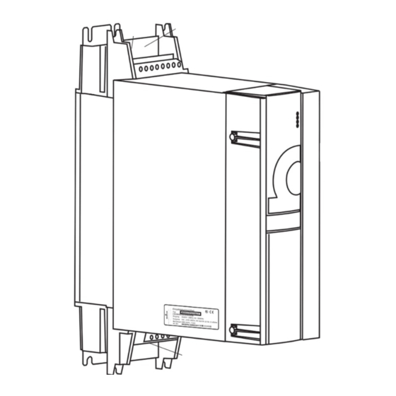
Page 125: Type Plate
Design and Operation Type plate On the type plate you will find, besides others, the type code of the device. Figure 55: Position of type plate Instruction handbook b maXX BM4400, BM4600, BM4700 Document No.: 5.12008.07 of 358... -
Page 126: Type Code
BM4XXX - XXX - XXXXX[Ryy] - [XXXXXXXX] - [XXX] - XX Power supply system TN or TT system IT system, „Grounded delta“, TN or TT system Instruction handbook b maXX BM4400, BM4600, BM4700 Document No.: 5.12008.07 Baumüller Nürnberg GmbH of 358... - Page 127 BM4XXX - XXX - XXXXX[Ryy] - [XXXXXXXX] - [XXX] - XX Brake resistor option Brake resistor with 16 Brake resistor with 10 Brake resistor with 5 Brake resistor with 3 Instruction handbook b maXX BM4400, BM4600, BM4700 Document No.: 5.12008.07 of 358...
- Page 128 BM4-F-SIE-01 Digital I/O without PE connection (4x IN,4x OUT) BM4-F-DIO-11 Fast digital I/O without PE connection (4 x IN, 4 x OUT) BM4-F-FIO-11 Instruction handbook b maXX BM4400, BM4600, BM4700 Document No.: 5.12008.07 Baumüller Nürnberg GmbH of 358...
- Page 129 SIL according to EN 61800. This device is not certificated for safety functions Devices with the approval mark of TÜV Rheinland and the Safety label provide a cer- tified safety function, only, refer to ZPage 29–. Instruction handbook b maXX BM4400, BM4600, BM4700 Document No.: 5.12008.07 of 358...
-
Page 130: Explanation Version Code
Design version power unit XXXX - X - XXX- XXX 3004 BM443X generation 1 from 3006 BM443X generation 2 XXXX - X - XXX- XXX Design version controller Instruction handbook b maXX BM4400, BM4600, BM4700 Document No.: 5.12008.07 Baumüller Nürnberg GmbH of 358... -
Page 131: Ul Notes
Additional only for Canada: NOTE Overvoltage Protection Device have to be installed in front of the input circuit of the device to limit the maximum overvoltage peak to 2.5 kV. Instruction handbook b maXX BM4400, BM4600, BM4700 Document No.: 5.12008.07 of 358... -
Page 132: Display And Operation Elements
Both LEDs UH1 and UH2 are not led through to the design cover. (UH1, UH2) Not available with BM4XXX - XXX - XX0XX and BM4XXX - XXX - XX1XX. Standard controller 6 LEDs ES controller Instruction handbook b maXX BM4400, BM4600, BM4700 Document No.: 5.12008.07 Baumüller Nürnberg GmbH of 358... - Page 133 No torque enable yet. green with short orange flashing memory access EEPROM, if possible do not switch off the device in this phase. orange with short green flashing: Instruction handbook b maXX BM4400, BM4600, BM4700 Document No.: 5.12008.07 of 358...
- Page 134 Identify the warning with help of the operating program ProDrive. Warning messages do not affect the operation of the device. For further information see ZTroubleshooting and fault correction– from page 229 Instruction handbook b maXX BM4400, BM4600, BM4700 Document No.: 5.12008.07 Baumüller Nürnberg GmbH of 358...
-
Page 135: 7-Segment Display
The display shows the error code in error status. Only errors are displayed, which enable an error reaction or have enabled one. Errors without reaction and warnings are not dis- played (see ZFault detection– from page 234). Instruction handbook b maXX BM4400, BM4600, BM4700 Document No.: 5.12008.07 of 358... -
Page 136: Address Switch S1 - S4 (Only Es Controller)
S1 and S2 as well as S3 and S4 each represent an 8 bit value. The IP address 192.168.0.0 is not permitted or, respectively, is reserved. For information on changing the base address, see the parameter manual. Example Switch Instruction handbook b maXX BM4400, BM4600, BM4700 Document No.: 5.12008.07 Baumüller Nürnberg GmbH of 358... - Page 137 Design and Operation Instruction handbook b maXX BM4400, BM4600, BM4700 Document No.: 5.12008.07 of 358...
- Page 138 Display and operation elements ® Figure 56: EtherCAT Address switch setting Instruction handbook b maXX BM4400, BM4600, BM4700 Document No.: 5.12008.07 Baumüller Nürnberg GmbH of 358...
- Page 139 Type code ES controller with CANopen BM4XXX - XXX - XXXXX[Ryy] - 2X (with CANopen interface) Baud rate S2 20 kBit/s 125 kBit/s 250 kBit/s 500 kBit/s 1 MBit/s Instruction handbook b maXX BM4400, BM4600, BM4700 Document No.: 5.12008.07 of 358...
- Page 140 Display and operation elements Address S3/S4 ® Figure 57: CANopen address switch Instruction handbook b maXX BM4400, BM4600, BM4700 Document No.: 5.12008.07 Baumüller Nürnberg GmbH of 358...
-
Page 141: Transport And Packaging
Climate class 2 K 3 as per EN 60721-3-2 m Temperature range - 25 °C up to + 70 °C m Vibration, shock, continuous shock class 2 M 1 as in EN 60721-3-2 Instruction handbook b maXX BM4400, BM4600, BM4700 Document No.: 5.12008.07 of 358... -
Page 142: Transport Inspection
Disposal of the packaging The packaging consists of cardboard, plastic, metal parts, corrugated cardboard and/or wood. h When disposing of the packaging, comply with the national regulations. Instruction handbook b maXX BM4400, BM4600, BM4700 Document No.: 5.12008.07 Baumüller Nürnberg GmbH of 358... -
Page 143: Mounting
The qualifications necessary for working with the device are, for example: m Occupational training or instruction in accordance with the standards of safety en- gineering for the care and use of appropriate safety equipment. Instruction handbook b maXX BM4400, BM4600, BM4700 Document No.: 5.12008.07 of 358... - Page 144 NOTICE! Danger due to electrostatic discharge. The connecting terminals of the device are partially at risk due from ESD. Therefore: Please heed the respective notes. Instruction handbook b maXX BM4400, BM4600, BM4700 Document No.: 5.12008.07 Baumüller Nürnberg GmbH of 358...
- Page 145 Danger area near the mechanical mounting Therefore: m Ensure that only qualified personnel, who are familiar with the safety notes and as- sembly instructions, mount this device. Wear safety gloves. Wear safety shoes. Instruction handbook b maXX BM4400, BM4600, BM4700 Document No.: 5.12008.07 of 358...
-
Page 146: Preparing For Mounting
Metal particles are flung when making the drill holes and the cutout sections. Therefore: Wear protective eye wear! h Preparing drill holes and cutout sections. Instruction handbook b maXX BM4400, BM4600, BM4700 Document No.: 5.12008.07 Baumüller Nürnberg GmbH of 358... -
Page 147: Drilling Patterns
Tolerance specifications Drill hole dimensioning ±0.2 mm Dimensioning openings +1.0 mm Relative tolerance of discretionary divisions ±0.1 mm 6.2.1.1 Drilling patterns BM441X Figure 59: Drilling pattern BM441X Instruction handbook b maXX BM4400, BM4600, BM4700 Document No.: 5.12008.07 of 358... -
Page 148: Drilling Patterns Bm442X
Preparing for mounting 6.2.1.2 Drilling patterns BM442X Figure 60: Drilling pattern BM442X 6.2.1.3 Drilling patterns BM4X3X Figure 61: Drilling pattern BM443X, BM463X Instruction handbook b maXX BM4400, BM4600, BM4700 Document No.: 5.12008.07 Baumüller Nürnberg GmbH of 358... -
Page 149: Drilling Patterns Bm4X4X
Mounting 6.2.1.4 Drilling patterns BM4X4X Figure 62: Drilling pattern BM444X, BM464X Instruction handbook b maXX BM4400, BM4600, BM4700 Document No.: 5.12008.07 of 358... -
Page 150: Drilling Patterns Bm4X5X
Preparing for mounting 6.2.1.5 Drilling patterns BM4X5X Figure 63: Drilling pattern BM445X, BM465X Hole Figure 64: Drilling pattern BM465X-FXX-3XXXX, BM475X-FXX-3XXXX Instruction handbook b maXX BM4400, BM4600, BM4700 Document No.: 5.12008.07 Baumüller Nürnberg GmbH of 358... -
Page 151: Drilling Patterns Bm4X6X
Mounting 6.2.1.6 Drilling patterns BM4X6X Figure 65: Drilling pattern BM446X, BM466X Instruction handbook b maXX BM4400, BM4600, BM4700 Document No.: 5.12008.07 of 358... - Page 152 Preparing for mounting Figure 66: Drilling pattern BM466X-FXX-3XXXX, BM4766-FXX-3XXXX Instruction handbook b maXX BM4400, BM4600, BM4700 Document No.: 5.12008.07 Baumüller Nürnberg GmbH of 358...
-
Page 153: Drilling Patterns Bm4X7X
Mounting 6.2.1.7 Drilling patterns BM4X7X Figure 67: Drilling pattern BM447X-F, BM477X-F Instruction handbook b maXX BM4400, BM4600, BM4700 Document No.: 5.12008.07 of 358... - Page 154 Preparing for mounting Figure 68: Drilling pattern BM447X-A Instruction handbook b maXX BM4400, BM4600, BM4700 Document No.: 5.12008.07 Baumüller Nürnberg GmbH of 358...
-
Page 155: Mounting Instructions
ZRequire- ments mounting plate for cold plate– on page 162 4 Mount the device. 5 Subsequently connect the water-cooling unit Instruction handbook b maXX BM4400, BM4600, BM4700 Document No.: 5.12008.07 of 358... - Page 156 4 x (5.3x15) c - Mounting space c = 5 mm c = 5 mm c = 5 mm c = 5 mm c = 5 mm Instruction handbook b maXX BM4400, BM4600, BM4700 Document No.: 5.12008.07 Baumüller Nürnberg GmbH of 358...
- Page 157 Mounting instruction BM445X-S/Z, BM465X-S/Z, BM446X-S/Z, BM466X-S/Z Device BM445X-S/Z BM446X-S/Z BM465X-Z BM466X-Z A - Screws 4x M8 4x M8 B - Washers 4x (8.4x21) 4x (8.4x21) C - Mounting space c=7 mm c=7 mm Instruction handbook b maXX BM4400, BM4600, BM4700 Document No.: 5.12008.07 of 358...
- Page 158 22 x M6 B - Spring washers 38 x DIN6796-6-FST 22 x DIN6796-6-FST C - Washers 38 x (6.4 x 12.5) 22 x (6.4 x 12.5) Instruction handbook b maXX BM4400, BM4600, BM4700 Document No.: 5.12008.07 Baumüller Nürnberg GmbH of 358...
- Page 159 16 x (5.3 x 15) 16 x (8.4x21) 20 x (8.4x21) Device BM465X-FXX-3XXXX BM466X-FXX-3XXXX BM475X-FXX-3XXXX BM476X-FXX-3XXXX A - Screws 18x M6 18 x M8 B - Washers 18 x (6.4x17) 18 x (8.4x21) Instruction handbook b maXX BM4400, BM4600, BM4700 Document No.: 5.12008.07 of 358...
- Page 160 The following required control cabinet mounting is only valid for control cabinets with protection class IP54 or higher. IP protection class for air-cooled through-hole devices: IP44 IP protection class for water-cooled through-hole devices: IP54 Instruction handbook b maXX BM4400, BM4600, BM4700 Document No.: 5.12008.07 Baumüller Nürnberg GmbH of 358...
- Page 161 Mounting Figure 73: Control cabinet mounting BM442X-A/F Instruction handbook b maXX BM4400, BM4600, BM4700 Document No.: 5.12008.07 of 358...
-
Page 162: Requirements Mounting Plate For Cold Plate
In case you refer to UL 508 C: There must be a pressure-relief valve with a threshold pres- sure of maximum 6 bar in the cooling circulation. Instruction handbook b maXX BM4400, BM4600, BM4700 Document No.: 5.12008.07 Baumüller Nürnberg GmbH... -
Page 163: Installation
Occupational training or instruction, in accordance with the standards of work safe- ty, for the care and use of appropriate safety equipment. Instruction handbook b maXX BM4400, BM4600, BM4700 Document No.: 5.12008.07 of 358... - Page 164 Pay heed to areas on the device that could be dangerous during the electrical in- stallation. m Pay heed to areas on the device that could still be electrically energized after op- eration. Instruction handbook b maXX BM4400, BM4600, BM4700 Document No.: 5.12008.07 Baumüller Nürnberg GmbH of 358...
-
Page 165: Voltage Test
Therefore: m Subsequent tests of the devices using high voltages may only be performed by Baumüller Nürnberg GmbH. m Disconnect the converter from the system during high-voltage testing! Instruction handbook b maXX BM4400, BM4600, BM4700 Document No.: 5.12008.07 of 358... -
Page 166: Demands On The Power Supply
If the requirements for the power supply are not complied, the device can be dam- aged or destroyed, thereby greatly endangering individuals. Therefore: m Prior to installation, ensure that the demands for power supply have been fulfilled. Instruction handbook b maXX BM4400, BM4600, BM4700 Document No.: 5.12008.07 Baumüller Nürnberg GmbH of 358... -
Page 167: Connection Instructions At Special Power Supply Systems
Connection to single phase grounded power supply systems (BM442X for IT systems, BM443X ... BM447X) right wrong Figure 75: Single phase connection (BM442X ... BM447X, basic units) Instruction handbook b maXX BM4400, BM4600, BM4700 Document No.: 5.12008.07 of 358... -
Page 168: Requirements To The Connecting Cables
Fuses must be installed to protect this device and the cables against overload and pos- sible damage/destruction through the electrical power supply. For data on the required fuses, see ZFuses– from page 273. Instruction handbook b maXX BM4400, BM4600, BM4700 Document No.: 5.12008.07 Baumüller Nürnberg GmbH of 358... -
Page 169: Pe Connection And Rcd Compatibility
Additional notes on building a CE-compliant system, that are im- perative to take heed of, can be found in the Baumüller manual „Mains filter BFN“, 5.09010. This manual can be obtained from Baumüller Nürnberg GmbH. Instruction handbook b maXX BM4400, BM4600, BM4700 Document No.: 5.12008.07 of 358... -
Page 170: Requirements For The Motor Temperature Sensors
(>10 mm m When installing, be sure to follow the correct sequence: power supply system - fuse - filter - choke - (ferrite core) - BM4400, BM4600, BM4700 - (motor filter) - motor. m Ensure that the motor cable is continuous, without interruption.... -
Page 171: Installation Procedure
Connect the protective conductor to the terminal PE (a fixed ground conductor con- nection is mandatorily specified). Connect 24 V power supply: Terminals X100-1/2, X100-5/6 (if UL 508C is being considered, then limit the current to 4 A). Instruction handbook b maXX BM4400, BM4600, BM4700 Document No.: 5.12008.07 of 358... - Page 172 14 Connect the safety relay (if existing) via X102-3 and X102-4 as well as X103-3 and X103-4 (connection data safety relay also see ZC.5 Technical data safety relay mod- ule– on page 350). Instruction handbook b maXX BM4400, BM4600, BM4700 Document No.: 5.12008.07 Baumüller Nürnberg GmbH of 358...
-
Page 173: Wiring Diagrams
+ 24 V ** X101-2 X101-3 X101-4 M 24 V X101-5 X101-6 BM4-ENC-XX Motor temperature Figure 77: Connection diagram with a directly controlled motor brake - basic units Instruction handbook b maXX BM4400, BM4600, BM4700 Document No.: 5.12008.07 of 358... - Page 174 194) or if you consider UL508C and the current of the brake is greater 4 A. Perhaps consider a limited operating voltage range of the brake because of the internal voltage drop up to max. 2.6 V. Instruction handbook b maXX BM4400, BM4600, BM4700 Document No.: 5.12008.07 Baumüller Nürnberg GmbH...
- Page 175 X101-2 X101-3 X101-4 M 24 V X101-5 X101-6 BM4-ENC-XX Motor temperature Brake voltage Figure 78: Connection diagram with motor brake controlled via an add. relay - basic units Instruction handbook b maXX BM4400, BM4600, BM4700 Document No.: 5.12008.07 of 358...
-
Page 176: Bm44Xx, Bm46Xx, Bm47Xx Power Module
Motor temperature U DC link Connection to other BM41XX or BM44XX units Figure 79: Connection diagram with a directly controlled motor brake - power modules Instruction handbook b maXX BM4400, BM4600, BM4700 Document No.: 5.12008.07 Baumüller Nürnberg GmbH of 358... - Page 177 194) or if you consider UL508C and the current of the brake is greater 4 A. Perhaps consider a limited operating voltage range of the brake because of the internal voltage drop up to max. 2.6 V. Instruction handbook b maXX BM4400, BM4600, BM4700 Document No.: 5.12008.07 of 358...
- Page 178 U DC link Brake voltage Connection to other BM41XX or BM44XX units Figure 80: Connection diagram with motor brake controlled via an additional relay - power modules Instruction handbook b maXX BM4400, BM4600, BM4700 Document No.: 5.12008.07 Baumüller Nürnberg GmbH of 358...
- Page 179 PELV) and table ZX100 (SELV/PELV)– on page 193. X101 Terminals for brake, motor temperature, see ZFigure 82– on page 181 and the following (SELV/PELV) and table X101 from ZPage 181–. Instruction handbook b maXX BM4400, BM4600, BM4700 Document No.: 5.12008.07 of 358...
-
Page 180: Terminal Overviews
Under certain conditions a mix mode of BM443X generation 1 and 2 is possible, see ZMix mode BM443X generation 1 and 2– on page 124. Instruction handbook b maXX BM4400, BM4600, BM4700 Document No.: 5.12008.07 Baumüller Nürnberg GmbH of 358... -
Page 181: Terminals Bm4412, Bm4413
Installation 7.10.2.1 Terminals BM4412, BM4413 Figure 82: Electrical connections for power supply, motor, ... for BM4412 and BM4413 Instruction handbook b maXX BM4400, BM4600, BM4700 Document No.: 5.12008.07 of 358... -
Page 182: Terminals Bm4414
7.10 Wiring diagrams 7.10.2.2 Terminals BM4414 Figure 83: Electrical connections for power supply, motor, ... for BM4414 Instruction handbook b maXX BM4400, BM4600, BM4700 Document No.: 5.12008.07 Baumüller Nürnberg GmbH of 358... -
Page 183: Terminals Bm442X
Installation 7.10.2.3 Terminals BM442X *) Do not apply terminals when using a power module! Figure 84: Electrical connections for power supply, motor, ... for BM442X Instruction handbook b maXX BM4400, BM4600, BM4700 Document No.: 5.12008.07 of 358... -
Page 184: Terminals Bm443X, Bm463X
7.10.2.4 Terminals BM443X, BM463X *) Do not apply terminals when using a power module!! Figure 85: Electrical connections for power supply, motor, ... for BM443X, BM463X Instruction handbook b maXX BM4400, BM4600, BM4700 Document No.: 5.12008.07 Baumüller Nürnberg GmbH of 358... -
Page 185: Terminals Bm444X, Bm464X
7.10.2.5 Terminals BM444X, BM464X *) Do not apply terminals when using a power module!! **) only BM444X-S/-A, BM464X-S/-A Figure 86: Electrical connections for power supply, motor, ... for BM444X, BM464X Instruction handbook b maXX BM4400, BM4600, BM4700 Document No.: 5.12008.07 of 358... -
Page 186: Terminals Bm445X, Bm446X, Bm465X, Bm466X
Electrical connections for power supply, motor, ... for BM445X, BM465X, BM446X, BM466X NOTE! The brake resistor is connected at BM445X and BM446X between Ba- and 1C1. Also see ZFigure 77– on page 173. Instruction handbook b maXX BM4400, BM4600, BM4700 Document No.: 5.12008.07 Baumüller Nürnberg GmbH of 358... -
Page 187: Terminals Bm466X, Bm476X
Installation 7.10.2.7 Terminals BM466X, BM476X Figure 88: Electrical connections for power supply, motor, ... for BM466X and BM476X Instruction handbook b maXX BM4400, BM4600, BM4700 Document No.: 5.12008.07 of 358... -
Page 188: Terminals Bm4755
7.10 Wiring diagrams 7.10.2.8 Terminals BM4755 Figure 89: Electrical connections for power supply, motor, ... for BM4755 Instruction handbook b maXX BM4400, BM4600, BM4700 Document No.: 5.12008.07 Baumüller Nürnberg GmbH of 358... -
Page 189: Terminals Bm447X, Bm4773
Installation 7.10.2.9 Terminals BM447X, BM4773 *) only BM447X-A Figure 90: Electrical connections for power supply, motor, ... for BM447X and BM4773 Instruction handbook b maXX BM4400, BM4600, BM4700 Document No.: 5.12008.07 of 358... - Page 190 The use of semiconductor fuses is obligatory at the power supply connection of BM447X, BM477X devices. Semiconductor fuses are required in the brake resistor circuit except the user assures the short-circuit protection of resistor and cable. Instruction handbook b maXX BM4400, BM4600, BM4700 Document No.: 5.12008.07 Baumüller Nürnberg GmbH...
-
Page 191: Electrical Connection Power Unit
. Also see ZCables power supply-device– from page 268. One cable of the mentioned cross section is sufficient for the operation. See also ZExplanation type code– on page 126. Instruction handbook b maXX BM4400, BM4600, BM4700 Document No.: 5.12008.07 of 358... - Page 192 ZCables power supply-device– from page 268. One cable of the mentioned cross section is sufficient for the operation. See also ZExplanation type code– on page 126. Instruction handbook b maXX BM4400, BM4600, BM4700 Document No.: 5.12008.07 Baumüller Nürnberg GmbH of 358...
- Page 193 Load capacity of connection 24 V power supply 1.5 mm Plug-in contact X100-1, X100-2, X100-5 and X100-6: max. 8.0 A, if you consider UL508C: max. 4.0 A Instruction handbook b maXX BM4400, BM4600, BM4700 Document No.: 5.12008.07 of 358...
-
Page 194: Requirements For The Screwing
7.10.4 Requirements for the screwing NOTE! Follow the mentioned torques in ZFigure 87– on page 186 and in ZFigure 90– page 189 to ensure an adequate conductivity. Instruction handbook b maXX BM4400, BM4600, BM4700 Document No.: 5.12008.07 Baumüller Nürnberg GmbH of 358... -
Page 195: Controller Terminals
Further notes for the usage of the PSI module are to be found in parameter manual. not BM44XX - XXX - XX0XX and BM44XX - XXX - XX1XX Instruction handbook b maXX BM4400, BM4600, BM4700 Document No.: 5.12008.07 of 358... - Page 196 X3-4: Quick stop (SELV/PELV) X3-5: Pulse enable (SELV/PELV) X3-6: Ready for use ON (normally closed contact) (SELV/PELV) Figure 91: Connection X100 and terminals of a standard controller Instruction handbook b maXX BM4400, BM4600, BM4700 Document No.: 5.12008.07 Baumüller Nürnberg GmbH of 358...
- Page 197 X4-7: Reference analog input 2 (SELV/PELV) X4-8: Reference analog output 1 and 2 (SELV/PELV) X4-9: Reference analog output 1 and 2 (SELV/PELV) X5, X6 depends on controller type, see ZPage 200– Instruction handbook b maXX BM4400, BM4600, BM4700 Document No.: 5.12008.07 of 358...
- Page 198 (e.g. from the company Ratioplast part No. 901SV232C6095 and part No. 901SV232T6095) Refer to ZInterface cable RS232– on page 272, if the cable is made by the customer. Instruction handbook b maXX BM4400, BM4600, BM4700 Document No.: 5.12008.07 Baumüller Nürnberg GmbH of 358...
- Page 199 10 Mbit green: 100 Mbit ® Ethernet cables are available as accessories (see ZAccessories Ethernet/EtherCAT .– on page 305). Instruction handbook b maXX BM4400, BM4600, BM4700 Document No.: 5.12008.07 of 358...
- Page 200 2: TX- 3: RX+ 4: reserved 5: reserved 6: RX- 7: reserved 8: reserved NOTE! ® Setting the IP address, see ZEtherCAT – from page 136. Instruction handbook b maXX BM4400, BM4600, BM4700 Document No.: 5.12008.07 Baumüller Nürnberg GmbH of 358...
- Page 201 500 ms on/ 500 ms off: PREOPERATIONAL 200 ms on/ 1 s off: SAFEOPERATIONAL OPERATIONAL ® Ethernet cables are available (see ZAccessories Ethernet/EtherCAT .– on page 305). Instruction handbook b maXX BM4400, BM4600, BM4700 Document No.: 5.12008.07 of 358...
- Page 202 NOTE! ® Setting the IP address, see ZCANopen – from page 139. ® CAN cables are available (see ZAccessories - CANopen .– on page 306). Instruction handbook b maXX BM4400, BM4600, BM4700 Document No.: 5.12008.07 Baumüller Nürnberg GmbH of 358...
-
Page 203: Encoder Connection Slot/Position A And B
160 mA Excitation frequency 4 kHz Excitation current 160 mA Transmission ratio BM4-F-ENC-01 BM4-F-ENC-11 0.28 NOTE Resolvers are to be used only for motors with maximum ten pole pairs. Instruction handbook b maXX BM4400, BM4600, BM4700 Document No.: 5.12008.07 of 358... - Page 204 Number of pole pairs resolver = 2 Requirements to the temperature sensor: Type Additional requirements Insulation KTY84 SELV/PELV NTC (MSKL) R = 1K at T < 2mA SELV/PELV protection Instruction handbook b maXX BM4400, BM4600, BM4700 Document No.: 5.12008.07 Baumüller Nürnberg GmbH of 358...
- Page 205 You can connect the temperature sensor separately at the module (in the D-sub con- nector) or at the power unit. Instruction handbook b maXX BM4400, BM4600, BM4700 Document No.: 5.12008.07 of 358...
- Page 206 RS422 incremental encoder track +A RS422 incremental encoder track -B Reserved* Reserved* Sense + 5V encoder supply Sense GND encoder supply D-sub-Tube 15-pin Reserved* Reserved* * do not assign Instruction handbook b maXX BM4400, BM4600, BM4700 Document No.: 5.12008.07 Baumüller Nürnberg GmbH of 358...
- Page 207 5 V Sense 0 V Sense D-sub socket 15-pin Reserved* Reserved* * do not assign NOTE A broken wire of the zero point cable is not detected by the controller. Instruction handbook b maXX BM4400, BM4600, BM4700 Document No.: 5.12008.07 of 358...
- Page 208 * do not assign Requirements to the temperature sensor: Type Additional requirements Insulation KTY84 SELV/PELV NTC (MSKL) R = 1 k at T < 2mA SELV/PELV protection Instruction handbook b maXX BM4400, BM4600, BM4700 Document No.: 5.12008.07 Baumüller Nürnberg GmbH of 358...
- Page 209 D-sub socket 15-pin not assigned CLK - NOTE ® Encoder cable for EnDat 2.2 without incremental signals (original encoder cable of Heidenhain), see ZEncoder cables– from page 307. Instruction handbook b maXX BM4400, BM4600, BM4700 Document No.: 5.12008.07 of 358...
- Page 210 D-sub socket 15-pin Data + Data- * do not assign NOTE The connection cable is not offered by Baumüller and must be made by the user! Instruction handbook b maXX BM4400, BM4600, BM4700 Document No.: 5.12008.07 Baumüller Nürnberg GmbH of 358...
- Page 211 Suitable encoder plug 2 Connect the cable shield with the cabinet of the circular connector and with the shield of the D-sub connector Figure 92: Connection cable BM4-F-ENC-07 Instruction handbook b maXX BM4400, BM4600, BM4700 Document No.: 5.12008.07 of 358...
- Page 212 D-sub socket 15-pin Data + Data- * do not assign NOTE The connection cable is not offered by Baumüller and must be made by the user! Instruction handbook b maXX BM4400, BM4600, BM4700 Document No.: 5.12008.07 Baumüller Nürnberg GmbH of 358...
- Page 213 Suitable encoder plug 2 Connect the cable shield with the cabinet of the circular connector and with the shield of the D-sub connector Abbildung 93: Connection cable BM4-F-ENC-17 Instruction handbook b maXX BM4400, BM4600, BM4700 Document No.: 5.12008.07 of 358...
- Page 214 24V power supply and a cable break in Data+/ Data- is identified. Otherwise the availability of the 24 V power supply is not checked and a broken cable is not detected by the controller. Instruction handbook b maXX BM4400, BM4600, BM4700 Document No.: 5.12008.07 Baumüller Nürnberg GmbH...
- Page 215 2 Connect the cable shield with the cabinet of the circular connector and with the shield of the D-sub connector 0,5 mm² 0,5 mm² Encoder plug, e. g. Temposonics Plug view Figure 94: Connection cable BM4-F-ENC-27 Instruction handbook b maXX BM4400, BM4600, BM4700 Document No.: 5.12008.07 of 358...
- Page 216 [C+], [C-], [D+], [D-] is not detected by the controller NOTE The connection cable is not offered by Baumüller and must be made by the user! Instruction handbook b maXX BM4400, BM4600, BM4700 Document No.: 5.12008.07 Baumüller Nürnberg GmbH of 358...
- Page 217 Suitable encoder plug 2 Connect the cable shield with the cabinet of the circular connector and with the shield of the D-sub connector Abbildung 95: Connection cable BM4-F-ENC-08 Instruction handbook b maXX BM4400, BM4600, BM4700 Document No.: 5.12008.07 of 358...
-
Page 218: Analog Input Slot/Position D And E
OUT 1 - , OUT 2 - D-sub male terminal 9-pin Max. cross-section Connection technology of connection 0.25 mm D-sub female, 9-pin, metal type or metalized Instruction handbook b maXX BM4400, BM4600, BM4700 Document No.: 5.12008.07 Baumüller Nürnberg GmbH of 358... - Page 219 Analog output voltage -10 V bis +10 V The analog output speed can be changed from „slow output“ to „fast output“ by the operation software and vice versa. Instruction handbook b maXX BM4400, BM4600, BM4700 Document No.: 5.12008.07 of 358...
-
Page 220: Digital Inputs Slot A To E/Position D
OUT 3 OUT 4 +24 V M 24 V Multi-pin connector 10-pin Max. cross-section Connection technology of connection 1.5 mm Connector, 10-pin Figure 96: Skinning length Instruction handbook b maXX BM4400, BM4600, BM4700 Document No.: 5.12008.07 Baumüller Nürnberg GmbH of 358... - Page 221 On tripping, there appears an error message on the controller. Limit the current to 2.5 A. (Due to this also UL 508 C with a maximum current of 4 A will be considered). Instruction handbook b maXX BM4400, BM4600, BM4700 Document No.: 5.12008.07...
- Page 222 7.11 Controller terminals Instruction handbook b maXX BM4400, BM4600, BM4700 Document No.: 5.12008.07 Baumüller Nürnberg GmbH of 358...
-
Page 223: Operation
Environmental conditions that are non-compliant can lead to property damage. Therefore: m Ensure that the environmental conditions are kept compliant during operation (see ZRequired environmental conditions– on page 55). Instruction handbook b maXX BM4400, BM4600, BM4700 Document No.: 5.12008.07 of 358... -
Page 224: Operating Concept
Disable the signal „quick stop“ only, if you must stop the installation/device as quick as possible. During operation the signal „quick stop“ must be available, so that the device supplies power. Instruction handbook b maXX BM4400, BM4600, BM4700 Document No.: 5.12008.07 Baumüller Nürnberg GmbH of 358... -
Page 225: Power On Switching Frequency / Dc Link Charging
DC link and the operation of the device. Below, the behavior described in the former paragraphs is characterized as „time-con- trolled charge procedure“. Instruction handbook b maXX BM4400, BM4600, BM4700 Document No.: 5.12008.07 of 358... -
Page 226: Power Supply Switch-On Frequency Bm443X Generation 2, Bm4X4X To Bm4X7X
DC link is charged to 50 V difference between peak power supply voltage and DC link voltage and there is a potential drop in blocking direction. The thyristor shows a behavior like a diode. Instruction handbook b maXX BM4400, BM4600, BM4700 Document No.: 5.12008.07 Baumüller Nürnberg GmbH... -
Page 227: Calculation Of The Maximum Permitted External Capacity
0.4 s It is recommended to choose the external capacity 20 % lower, because the charging time can vary depending on the height of the power supply voltage. Instruction handbook b maXX BM4400, BM4600, BM4700 Document No.: 5.12008.07 of 358... -
Page 228: Effects Of The Different Charging Circuits
39 µH 19.8 mF 0.12 s 0.29 s 0.51 s 0.7 s BM477X 32.6 µH 19.8 mF 0.1 s 0.24 s 0.4 s 0.58 s Instruction handbook b maXX BM4400, BM4600, BM4700 Document No.: 5.12008.07 Baumüller Nürnberg GmbH of 358... -
Page 229: Troubleshooting And Fault Correction
In particular, reacting to error indications and conditions requires that the oper- ator must have special knowledge. Instruction handbook b maXX BM4400, BM4600, BM4700 Document No.: 5.12008.07 of 358... -
Page 230: Monitoring Functions
Pulse inhibit is generated after adjustable time period X: implemented -: not possible Only when using the KTY sensor Adjustable with P0299 Adjustable with P0298 Not available at power modules Instruction handbook b maXX BM4400, BM4600, BM4700 Document No.: 5.12008.07 Baumüller Nürnberg GmbH of 358... - Page 231 Pulse inhibit is generated after adjustable time period X: implemented -: not possible Only when using the KTY sensor Adjustable with P0299 Adjustable with P0298 Not available at power modules Instruction handbook b maXX BM4400, BM4600, BM4700 Document No.: 5.12008.07 of 358...
- Page 232 In case the temperature is higher than the warning threshold, the controller generates a warning. m In case the temperature is too high, the pulses are inhibited immediately. Instruction handbook b maXX BM4400, BM4600, BM4700 Document No.: 5.12008.07 Baumüller Nürnberg GmbH...
- Page 233 „drive blocked“ is generated by the controller and the pulses are inhibited immediately. m Motor speed = 0 m The motor current which is supplied by the device is equal to the set motor limit current (current limit). Instruction handbook b maXX BM4400, BM4600, BM4700 Document No.: 5.12008.07 of 358...
-
Page 234: Fault Detection
The procedure is repeated as soon as all errors were displayed. Example: Error 125 and 91 are generated: Start Time Error code display Figure 97: Error messages 7-segment display Instruction handbook b maXX BM4400, BM4600, BM4700 Document No.: 5.12008.07 Baumüller Nürnberg GmbH of 358... - Page 235 Please contact Baumüller Nürnberg GmbH or visit our website www.baumueller.de for download the latest version of ProDrive, if the controller software version is not available in your ProDrive version. Instruction handbook b maXX BM4400, BM4600, BM4700 Document No.: 5.12008.07 of 358...
- Page 236 ProDrive start screen Display the „error message“ in ProDrive. h Open navigation with click on in front of „Management“. Figure 100: Project navigation in ProDrive Instruction handbook b maXX BM4400, BM4600, BM4700 Document No.: 5.12008.07 Baumüller Nürnberg GmbH of 358...
- Page 237 Error possibilities are e. g.: torque limit = 0 has been set or notch position is not cor- rect (also see parameter manual b maXX 4000). If no LEDs are lighting up on the front side of the device, check the 24V supply. Instruction handbook b maXX BM4400, BM4600, BM4700 Document No.: 5.12008.07 of 358...
-
Page 238: Error Handling
An exception here are errors, which have to have an immediate pulse inhibit as a consequence. These can not be changed due to safety reasons. Instruction handbook b maXX BM4400, BM4600, BM4700 Document No.: 5.12008.07 Baumüller Nürnberg GmbH... -
Page 239: Error Reset
But the drive still does not start. Therefore you then need a second rising edge for the enable. Additional data according the subject resetting of error messages is available in the „pa- rameter manual“. Instruction handbook b maXX BM4400, BM4600, BM4700 Document No.: 5.12008.07 of 358... -
Page 240: Error Parameters, Error Messages, Error Reactions
Error handling 9.4.2 Error parameters, error messages, error reactions Figure 103: Survey error list Instruction handbook b maXX BM4400, BM4600, BM4700 Document No.: 5.12008.07 Baumüller Nürnberg GmbH of 358... -
Page 241: Error Messages (2Nd Level)
Reaction Troubleshooting reserved Watchdog error Restart b maXX 4000 Incorrect or unexpected interrupt has occurred NMI Interrupt / bus error 4 to 15 reserved, not assigned = 0 Instruction handbook b maXX BM4400, BM4600, BM4700 Document No.: 5.12008.07 of 358... - Page 242 Enter with a valid value Communication error adjustable Establish connection again or set parameter P0290 to ProDrive controller 46 to 47 reserved, not assigned = 0 Instruction handbook b maXX BM4400, BM4600, BM4700 Document No.: 5.12008.07 Baumüller Nürnberg GmbH of 358...
- Page 243 Undervoltage 24 V 69 to 78 reserved, not assigned = 0 Power supply monitor - group error adjustable See ZError power supply monitor– on page 253 (= 3rd level) Instruction handbook b maXX BM4400, BM4600, BM4700 Document No.: 5.12008.07 of 358...
- Page 244 = 0 Group error find notch position ZError at finding notch position– on page 254 103 to 111 reserved, not assigned = 0 Instruction handbook b maXX BM4400, BM4600, BM4700 Document No.: 5.12008.07 Baumüller Nürnberg GmbH of 358...
- Page 245 Use an encoder module with temperature sensor Memory capacity in the encoder for electronic adjustable Use another encoder with a greater memory type plate too small 142 to 143 reserved, not assigned = 0 Instruction handbook b maXX BM4400, BM4600, BM4700 Document No.: 5.12008.07 of 358...
- Page 246 SSI encoder emulation module is not available Install SSI encoder emulation module Error in set value source encoder 1 or encoder See error messages encoder 1 or 2 Instruction handbook b maXX BM4400, BM4600, BM4700 Document No.: 5.12008.07 Baumüller Nürnberg GmbH of 358...
- Page 247 Replace the controller cartridge EEPROM is reset The data in the EEPROM is reset, please safe all data records 188 to 191 reserved, not assigned = 0 Instruction handbook b maXX BM4400, BM4600, BM4700 Document No.: 5.12008.07 of 358...
- Page 248 Overspeed Open loop Check parameterization and reduce speed Export restriction: Reduce speed Maximum electrical frequency exceeded 214 to 223 not assigned = 0 Instruction handbook b maXX BM4400, BM4600, BM4700 Document No.: 5.12008.07 Baumüller Nürnberg GmbH of 358...
- Page 249 Return motion target position was not reached adjustable Application error adjustable (enabled by P0302 bit 1) P0216 Error CANsync Error No. Meaning Reaction Troubleshooting 240 to 255 not assigned = 0 Instruction handbook b maXX BM4400, BM4600, BM4700 Document No.: 5.12008.07 of 358...
-
Page 250: Sub-Error Messages (3Rd Level)
Data field is not changeable in its size Word address outside of data field Data field is nonexistent Wrong data checksum No response Invalid response Restart b maXX 4000 Instruction handbook b maXX BM4400, BM4600, BM4700 Document No.: 5.12008.07 Baumüller Nürnberg GmbH of 358... - Page 251 Check the encoder cable and the encoder connection No response of Hiperface® encoder Undefined response to encoder command Encoder type not accepted Use another encoder type 68 to 79 reserved Instruction handbook b maXX BM4400, BM4600, BM4700 Document No.: 5.12008.07 of 358...
- Page 252 1 and function module 2. The term „encoder 1“ or „encoder 2“ in the column „device part“ stands for one of the five currently existing encoder module types. Instruction handbook b maXX BM4400, BM4600, BM4700 Document No.: 5.12008.07 Baumüller Nürnberg GmbH...
- Page 253 Power supply monitor has detected power sup- adjustable ply frequency below/equal than lower frequency limit Power supply monitor has detected power sup- adjustable ply frequency higher/equal than upper fre- quency limit Instruction handbook b maXX BM4400, BM4600, BM4700 Document No.: 5.12008.07 of 358...
- Page 254 The amplitude of the injected signal is too low P2149) is at maximum already, then reduce the frequency of the to detect the 2nd harmonic current P2121 Instruction handbook b maXX BM4400, BM4600, BM4700 Document No.: 5.12008.07 Baumüller Nürnberg GmbH of 358...
- Page 255 AIO-04: current < 4 mA Current supply not connected, cable break or short cir- reaction cuit AIO-04: current > 20 mA Current supply supplies a current too high reaction Instruction handbook b maXX BM4400, BM4600, BM4700 Document No.: 5.12008.07 of 358...
- Page 256 Invalid value at set value parameter No. 10 adjustable 4138 Invalid value at set value parameter No. 11 adjustable 4139 Invalid value at set value parameter No. 12 adjustable Instruction handbook b maXX BM4400, BM4600, BM4700 Document No.: 5.12008.07 Baumüller Nürnberg GmbH of 358...
- Page 257 Select another parameter cyclic writable 4175 Configuration cyclic services: Invalid parameter No. adjustable 4176 Wrong option module error code adjustable Contact Baumüller Nürnberg GmbH 4177 to 8192 reserved Instruction handbook b maXX BM4400, BM4600, BM4700 Document No.: 5.12008.07 of 358...
-
Page 258: Warnings
Temperature threshold 1 exceeded Reduce the power output of the motor Temperature threshold 2 exceeded I²t threshold exceeded 35 to 47 not assigned = 0 Instruction handbook b maXX BM4400, BM4600, BM4700 Document No.: 5.12008.07 Baumüller Nürnberg GmbH of 358... - Page 259 Power supply monitor has detected power supply Power supply monitor has detected power supply frequency frequency higher than warning upper frequency higher than warning upper frequency limit P2061 limit P2061 Instruction handbook b maXX BM4400, BM4600, BM4700 Document No.: 5.12008.07 of 358...
- Page 260 Error handling Instruction handbook b maXX BM4400, BM4600, BM4700 Document No.: 5.12008.07 Baumüller Nürnberg GmbH of 358...
-
Page 261: Maintenance
Pay heed to areas on the device that could be dangerous during the electrical in- stallation. m Pay heed to areas on the device that could still be electrically energized after op- eration. Figure 104: Hazard areas during electrical installation Instruction handbook b maXX BM4400, BM4600, BM4700 Document No.: 5.12008.07 of 358... -
Page 262: Environmental Condition
Does the motor overheat during operation? Regularly sched- Before checking, switch off the input voltage and wait until the device's capacitors have uled inspection: discharged. Instruction handbook b maXX BM4400, BM4600, BM4700 Document No.: 5.12008.07 Baumüller Nürnberg GmbH of 358... - Page 263 This discharge time must be posted, together with an IEC 60417-5036 (2002-10) warn- ing symbol, on a clearly visible location of the control cabinet. Instruction handbook b maXX BM4400, BM4600, BM4700 Document No.: 5.12008.07 of 358...
-
Page 264: Periodic Maintenance
Is there any deformation, cracking, damage or Visual inspection color change on the device as a result of overheat- ing or aging? Are there any dust or dirt deposits? Visual inspection Instruction handbook b maXX BM4400, BM4600, BM4700 Document No.: 5.12008.07 Baumüller Nürnberg GmbH of 358... - Page 265 Visual inspection and odor check changes? Is there any cracking, damage, deformation or Visual inspection corrosion? Is there any leaking fluid or deformation of the Visual inspection capacitors? Instruction handbook b maXX BM4400, BM4600, BM4700 Document No.: 5.12008.07 of 358...
-
Page 266: Repairs
Ostendstr. 80 - 90 90482 Nuremberg Germany Tel. +49 9 11 54 32 - 0 Fax: +49 9 11 54 32 - 1 30 Mail: mail@baumueller.de Internet: www.baumueller.de Instruction handbook b maXX BM4400, BM4600, BM4700 Document No.: 5.12008.07 Baumüller Nürnberg GmbH of 358... -
Page 267: Accessories And Spare Parts
ARTS Accessories/spare parts for devices of the b maXX series are listed in this appendix. Product management is happy to handle any queries and suggestions on accessory parts. Instruction handbook b maXX BM4400, BM4600, BM4700 Document No.: 5.12008.07 of 358... -
Page 268: Cabling
The installing of the cables is user-defined. NOTE BM4435, BM4635 The BM4435 has an input current of 53 A, the appropriate mains filter (BFN3-1-56-001) has a rated current of 53 A, too. Instruction handbook b maXX BM4400, BM4600, BM4700 Document No.: 5.12008.07 Baumüller Nürnberg GmbH... - Page 269 ,Cable lug width max. 35 mm: Screw two cable lugs to the current bar at maximum- one on the front side, one on the reverse side of the bar. Instruction handbook b maXX BM4400, BM4600, BM4700 Document No.: 5.12008.07 of 358...
-
Page 270: Cables Device-Motor
186 Screw maximum two cable lugs to the current bar - one on the front side, one on the reverse side of the bar. Instruction handbook b maXX BM4400, BM4600, BM4700 Document No.: 5.12008.07 Baumüller Nürnberg GmbH of 358... -
Page 271: Cable Control Voltage Supply/Signals
/without wire end ferrules (plug-in terminal) The installing of the cables is user-defined. The length of the cable has no influence on the compliance to the EMC regulation. Instruction handbook b maXX BM4400, BM4600, BM4700 Document No.: 5.12008.07 of 358... -
Page 272: Interface Cable Rs232
D-sub connector, 9-pin, male, cabinet plastics metalized 2 Connect the cable shield with the cabinet and with the shield of the D-sub connector Figure 105: Interface cable RS 232 Instruction handbook b maXX BM4400, BM4600, BM4700 Document No.: 5.12008.07 Baumüller Nürnberg GmbH of 358... -
Page 273: Fuses
NOTE! Use suitable fuses with the tripping characteristic gL or gR. Instruction handbook b maXX BM4400, BM4600, BM4700 Document No.: 5.12008.07 of 358... - Page 274 245 000 A BM446X BM466X BM476X 1 051 000 A BM447X BM477X Use fuses that fall below the specified cutoff integral (i ) in the operating point. Instruction handbook b maXX BM4400, BM4600, BM4700 Document No.: 5.12008.07 Baumüller Nürnberg GmbH of 358...
-
Page 275: Fuses Bm441X
20A/1000V: 2038404/20A 25A/1000V: 2038404/25A 32A/1000V: 2038404/32A Siemens 000 16A/690V: 3NE1 813-0 U 00 25A/690V: 3NE8 015-1 U 20A/690V: 3NE8 714-1 25A/690V: 3NE8 715-1 0 32A/1000V: 3NE4 101 Size Instruction handbook b maXX BM4400, BM4600, BM4700 Document No.: 5.12008.07 of 358... - Page 276 00 25A/690V: 3NE8 015-1 U 35A/690V: 3NE8 003-1 U 25A/690V: 3NE8 715-1 U 32A/690V: 3NE8 701-1 U 0 32A/1000V: 4NE4 101 40A/1000V: 4NE4 102 Size Instruction handbook b maXX BM4400, BM4600, BM4700 Document No.: 5.12008.07 Baumüller Nürnberg GmbH of 358...
-
Page 277: Fuses Bm442X
00 20A/690V: 2047720/20A 25A/690V: 2047720/25A Siemens 00 16A/690V: 3NE1 813-0 U 20A/660V: 3NE8 714 25A/660V: 3NE8 715 25A/660V: 3NE8 015 32A/660V: 3NE8 701 0 32A/1000V: 3NE4 101 U Size Instruction handbook b maXX BM4400, BM4600, BM4700 Document No.: 5.12008.07 of 358... - Page 278 000 20A/690V: 6,9 URD 000 PV 020 25A/690V: 6,9 URD 000 PV 025 32A/690V: 6,9 URD 000 PV 032 40A/690V: 6,9 URD 000 PV 040 Size Instruction handbook b maXX BM4400, BM4600, BM4700 Document No.: 5.12008.07 Baumüller Nürnberg GmbH of 358...
- Page 279 000 25A/690V: 6,9 URD 000 PV 025 32A/690V: 6,9 URD 000 PV 032 40A/690V: 6,9 URD 000 PV 040 50A/690V: 6,9 URD 000 PV 050 Siemens 00 40A/660V: 3NE8 702 Size Instruction handbook b maXX BM4400, BM4600, BM4700 Document No.: 5.12008.07 of 358...
-
Page 280: Fuses Bm4X3X
Full-range fuses gR (device and cable) BM443X generation 2 and BM4632, design type NH SIBA 1 80A/690V: 2021134.80 U Siemens 000 80A/690V: 3NE1820-0 U 00 100A/690V: 3NE1021-2 U Size Instruction handbook b maXX BM4400, BM4600, BM4700 Document No.: 5.12008.07 Baumüller Nürnberg GmbH of 358... -
Page 281: Fuses Bm4X4X
For the connection of an additional DC link capacity or the parallel operation of up to five devices suitable, that means the DC link of several devices is connected with at the same time existent power supply connec- tion of every device. Instruction handbook b maXX BM4400, BM4600, BM4700 Document No.: 5.12008.07 of 358... - Page 282 Full-range fuses gR (device and cable) BM4641, design type NH SIBA 1 100A/690V: 2021134.100 U Siemens 00 125A/690V: 3NE1022-2 U Size Instruction handbook b maXX BM4400, BM4600, BM4700 Document No.: 5.12008.07 Baumüller Nürnberg GmbH of 358...
- Page 283 BM4642, design type NH Bussmann 000 200A/690V: 170M1570D U Ferraz Shawmut 00 160A/690V: NH00GS69V16PV SIBA 00C/80 200A/690V: 2028220.200 U 1 250A/690V: 2021120.250 U Siemens 00 160A/690V: 3NE8024-1 U Size Instruction handbook b maXX BM4400, BM4600, BM4700 Document No.: 5.12008.07 of 358...
-
Page 284: Fuses Bm4X5X
For the connection of an additional DC link capacity or the parallel operation of up to five devices suitable, that means the DC link of several devices is connected with at the same time existent power supply connec- tion of every device. Instruction handbook b maXX BM4400, BM4600, BM4700 Document No.: 5.12008.07 Baumüller Nürnberg GmbH... - Page 285 For the connection of an additional DC link capacity or the parallel operation of up to five devices suitable, that means the DC link of several devices is connected with at the same time existent power supply connec- tion of every device. Instruction handbook b maXX BM4400, BM4600, BM4700 Document No.: 5.12008.07 of 358...
- Page 286 BM4651, design type NH Bussmann 00 315A/690V: 170M1572D U Ferraz Shawmut 1 250A/690V: NH1GS69V250PV SIBA 00C/80 350A/690V: 2018920.350 U Siemens 1/110 250A/1000V: 3NE3227 U Size Instruction handbook b maXX BM4400, BM4600, BM4700 Document No.: 5.12008.07 Baumüller Nürnberg GmbH of 358...
- Page 287 2 400A/660V: 170M5808 U 450A/660V: 170M5809 U 3 500A/660V: 170M6808 U SIBA 00 350A/690V: 2018920.350 U Siemens 00 315A/1000V: 3NE8731-1 U 1 315A/1000V: 3NE3230-0B U 350A/1000V: 3NE3231 U Size Instruction handbook b maXX BM4400, BM4600, BM4700 Document No.: 5.12008.07 of 358...
-
Page 288: Fuses Bm4X6X
350A/660V: 170M3818 400A/660V: 170M3819 2 400A/660V: 170M5808 450A/660V: 170M5809 500A/660V: 170M5810 550A/660V: 170M5811 630A/660V: 170M5812 3 500A/660V: 170M6808 550A/660V: 170M6809 630A/660V: 170M6810 700A/660V: 170M6811 Size Instruction handbook b maXX BM4400, BM4600, BM4700 Document No.: 5.12008.07 Baumüller Nürnberg GmbH of 358... - Page 289 For the connection of an additional DC link capacity or the parallel operation of up to five devices suitable, that means the DC link of several devices is connected with at the same time existent power supply connec- tion of every device. Instruction handbook b maXX BM4400, BM4600, BM4700 Document No.: 5.12008.07 of 358...
- Page 290 BM4662, design type NH Bussmann 2 550A/690V: 170M5811D U Ferraz Shawmut 2 400A/690V: NH2GS69V400PV SIBA 1/110 630A/690V: 2061331.630 U Siemens 1/110 450A/1000V: 3NE3233 2/110 560A/1000V: 3NE3335 Size Instruction handbook b maXX BM4400, BM4600, BM4700 Document No.: 5.12008.07 Baumüller Nürnberg GmbH of 358...
- Page 291 3 550A/660V: 170M6809 U Ferraz Shawmut 2 500A/690V: 6,9URD2PV0500 3 560A/690V: 6,9URD2PV0560 SIBA 1 / 110 mm 500A/690V: 2061331.500 U Siemens 1 / 110 mm 450A/1000V: 3NE3233 2 450A/1000V: 3NE3333 Size Instruction handbook b maXX BM4400, BM4600, BM4700 Document No.: 5.12008.07 of 358...
-
Page 292: Fuses Bm447X
500A/560A fuses and therefore the risk of fuse trip- ping at normal run (without real error) is reduced. BM4473, BM4773: Siemens 2 800A/800V: 3NE3 338-8 u Size Instruction handbook b maXX BM4400, BM4600, BM4700 Document No.: 5.12008.07 Baumüller Nürnberg GmbH of 358... -
Page 293: Ul Fuse In The Ballast Circuit
UL 248 with a triggering current of maximum 4 A. HINWEIS! If the current consumption is lower than 4 A, several connections can be protected together with a UL-listed fuse (release current max. 4 A). Instruction handbook b maXX BM4400, BM4600, BM4700 Document No.: 5.12008.07 of 358... -
Page 294: Mains Filters
Storage temperature range - 25 °C to +85 °C Operating environment Outside of residential areas Operating temperature range -25 °C to +85 °C (rated temperature 50 °C) Instruction handbook b maXX BM4400, BM4600, BM4700 Document No.: 5.12008.07 Baumüller Nürnberg GmbH of 358... -
Page 295: Electrical Data Mains Filter
/ 2 s line - housing: 2720 V / 2 s Connection L1/L2/L3: safe-to-touch screw terminals PE: bolt M10 Maximum connection 95 mm cross-section Protection class IP 20 Instruction handbook b maXX BM4400, BM4600, BM4700 Document No.: 5.12008.07 of 358... - Page 296 11mm bar with hole 14mm PE: bolt M10 PE: bolt M12 Power loss (typical) 31 W 48 W 84 W Protection class IP 00 Instruction handbook b maXX BM4400, BM4600, BM4700 Document No.: 5.12008.07 Baumüller Nürnberg GmbH of 358...
- Page 297 Risk of fatal injury due to high leakage current! Therefore: m The cross-section of the protective ground conductor must be at least 10 mm (EN 61800-5-1, Chapter 4.3.5.5.2). Instruction handbook b maXX BM4400, BM4600, BM4700 Document No.: 5.12008.07 of 358...
-
Page 298: Mains Filter Selection
600 A BFN-3-1 - 0600 - 001 373901 BFN-3-1 - 0600 - 101 419997 1000 A BFN-3-1 - 1000 - 101 423683 Rated temperature = 50° C Instruction handbook b maXX BM4400, BM4600, BM4700 Document No.: 5.12008.07 Baumüller Nürnberg GmbH of 358... - Page 299 439387 400 A BFN-3-1 - 400 - 002 373898 600 A BFN-3-1 - 600 - 002 373902 BFN-3-1 - 600 - 102 439388 Rated temperature = 50° C Instruction handbook b maXX BM4400, BM4600, BM4700 Document No.: 5.12008.07 of 358...
-
Page 300: Power Chokes
10 % per 1000 m. At operation temperatures from 40 °C up to 55 °C the current must be reduced for 1 % per °C Instruction handbook b maXX BM4400, BM4600, BM4700 Document No.: 5.12008.07 Baumüller Nürnberg GmbH of 358... - Page 301 160 A 0,18 mH BK3-0160/0196 456723 BM4651 190 A 0,15 mH BK3-0190/0232 456725 BM4652 240 A 0,12 mH BK3-0240/0294 456728 BM4661 285 A 0,10 mH BK3-0285/0350 456729 BM4662 Instruction handbook b maXX BM4400, BM4600, BM4700 Document No.: 5.12008.07 of 358...
- Page 302 39 µH BK3-0750/0920 368389 BM4473, BM4773 920 A 32.6 µH BK3-0900/1100 368390 BM4473, BM4773 1020 A 28 µH BK3-1020/1250 395020 Figure 108: Figure power choke Instruction handbook b maXX BM4400, BM4600, BM4700 Document No.: 5.12008.07 Baumüller Nürnberg GmbH of 358...
- Page 303 1430/1750-001 408700 1430 1750 480 350 430 430 210 13x18 150 60x10 for M12 1680/2050-001 408701 1680 2050 480 350 430 430 210 13x18 170 60x10 for M12 Instruction handbook b maXX BM4400, BM4600, BM4700 Document No.: 5.12008.07 of 358...
-
Page 304: Baumüller Accessories
(e.g. from the company Ratioplast part no. 901SV232C6095 and part no. 901SV232T6095) Optically decoupled interface cable Interface Name Length Part No. X1 (RS 232) Programming cable on request Further lengths on request. Instruction handbook b maXX BM4400, BM4600, BM4700 Document No.: 5.12008.07 Baumüller Nürnberg GmbH of 358... -
Page 305: Accessories Ethernet/Ethercat
Crossover package consisting of cross connector (part No. 365463) and Cat5 cable 0.5 m (part No. 325160) Type Part No. K-ETH-CROSS-ADAPTER 365464 Modular connector, RJ45 female - RJ45 female, crossover, Cat5, shielded Type Part No. K-ETH-CROSS-KUPPLUNG 365463 Instruction handbook b maXX BM4400, BM4600, BM4700 Document No.: 5.12008.07 of 358... -
Page 306: Accessories - Canopen
Terminated plug RJ45 (Termination plug CAN, RJ45 with pin assignment according to CIA-standard, 120 , 0.25 W) Type Part No. BM4-CAN-T01 346408 Instruction handbook b maXX BM4400, BM4600, BM4700 Document No.: 5.12008.07 Baumüller Nürnberg GmbH of 358... -
Page 307: Encoder Cables
240520 448976 45 m 217567 240521 448978 50 m 217568 240522 448979 55 m 217569 244033 448981 60 m 217570 245484 448982 70 m 232088 Bold: preferred length Instruction handbook b maXX BM4400, BM4600, BM4700 Document No.: 5.12008.07 of 358... - Page 308 In case there is another assignment of the pins, the cable will not operate and defects as well as at the encoder module and also at the encoder can appear! Instruction handbook b maXX BM4400, BM4600, BM4700 Document No.: 5.12008.07 Baumüller Nürnberg GmbH...
- Page 309 448830 50 m 388419 378022 70 m 384473 90 m 387391 Bold: preferred length NOTE With this encoder cables no evaluation of the motor temperature sensor is possible! Instruction handbook b maXX BM4400, BM4600, BM4700 Document No.: 5.12008.07 of 358...
- Page 310 In case there is another assignment of the pins, the cable will not operate and defects as well as at the encoder module and also at the encoder can appear! Instruction handbook b maXX BM4400, BM4600, BM4700 Document No.: 5.12008.07 Baumüller Nürnberg GmbH...
- Page 311 (original encoder cable of Fa. Heidenhain), lengths on request. Cable with M12 connector 8-pin completely assembled with female connector plug and male D-sub connector. Item no. Fa. Heidenhain 524599-xx (xx: length) Instruction handbook b maXX BM4400, BM4600, BM4700 Document No.: 5.12008.07 of 358...
-
Page 312: Design Cover And Connectors
Phoenix: FK-MCP 1,5/4-ST-3,81, 1851067 BM441X - XXX - 01 BM441X - XXX - 02 BM44XX - XX1, BM44XX - XX3 BM44XX - XX2, BM44XX - XX4 Instruction handbook b maXX BM4400, BM4600, BM4700 Document No.: 5.12008.07 Baumüller Nürnberg GmbH of 358... -
Page 313: Shutdown, Storage
This discharge time must be posted, together with an IEC 60417-5036 (2002-10) warning symbol, on a clearly visible location of the control cabinet. Instruction handbook b maXX BM4400, BM4600, BM4700 Document No.: 5.12008.07 of 358... -
Page 314: Requirements To The Executing Personnel
5 at transportation pay attention to, that the device is not damaged by wrong storage or severe shocks, also see ZWhat to observe when transporting– auf Seite 141. Instruction handbook b maXX BM4400, BM4600, BM4700 Document No.: 5.12008.07 Baumüller Nürnberg GmbH of 358... -
Page 315: Storage Conditions
Consider, that it is imperative, to connect the accordingly prescribed line commu- tating reactor for this forming procedure. Devices, where no line commutating re- actor is necessary can directly be supplied with mains voltage. Instruction handbook b maXX BM4400, BM4600, BM4700 Document No.: 5.12008.07 of 358... -
Page 316: Recommissioning
Consider, that it is imperative, to connect the accordingly prescribed line commu- tating reactor for this forming procedure. Devices, where no line commutating re- actor is necessary can directly be supplied with mains voltage. Instruction handbook b maXX BM4400, BM4600, BM4700 Document No.: 5.12008.07 Baumüller Nürnberg GmbH... -
Page 317: Disposal
This discharge time must be posted, together with an IEC 60417-5036 (2002-10) warn- ing symbol, on a clearly visible location of the control cabinet. Instruction handbook b maXX BM4400, BM4600, BM4700 Document No.: 5.12008.07 of 358... - Page 318 The beryllium dust that is generated upon opening is injurious to the health. Do not open electronic components. m Dispose of capacitors, semiconductor modules and electronic scrap as special waste. Instruction handbook b maXX BM4400, BM4600, BM4700 Document No.: 5.12008.07 Baumüller Nürnberg GmbH of 358...
-
Page 319: Disposal Facilities/Authorities
In case of doubt, consult the bureau of commerce or environmental protection authority responsible for your company. Instruction handbook b maXX BM4400, BM4600, BM4700 Document No.: 5.12008.07 of 358... - Page 320 13.2 Disposal facilities/authorities Instruction handbook b maXX BM4400, BM4600, BM4700 Document No.: 5.12008.07 Baumüller Nürnberg GmbH of 358...
-
Page 321: Appenidx A - Abbreviations
Effective value, alternating voltage ID No. Identification number DC-link voltage PPR count of incremental encoder Volt Impulse inhibit Association for Electrical, Elec- tronic & Information Technologies International Organization Standardization DC-link Instruction handbook b maXX BM4400, BM4600, BM4700 Document No.: 5.12008.07 of 358... - Page 322 Instruction handbook b maXX BM4400, BM4600, BM4700 Document No.: 5.12008.07 Baumüller Nürnberg GmbH of 358...
-
Page 323: Appenidx B - Declaration Of Conformity
B - D PPENDIX ECLARATION OF ONFORMITY Declaration of conformity Instruction handbook b maXX BM4400, BM4600, BM4700 Document No.: 5.12008.07 of 358... - Page 324 Part 3: EMC requirements and specific test methods Attention should be paid to the safety instructions in the manual. Nuremberg / 14-Jun-2016 Location / Date Instruction handbook b maXX BM4400, BM4600, BM4700 Document No.: 5.12008.07 Baumüller Nürnberg GmbH of 358...
- Page 325 Machinery Directive 2006/42/EC. Nuremberg / 14-Jun-2016 Location / Date Subject to change of this declaration of EC conformity without notice. Actual valid edition on request. Instruction handbook b maXX BM4400, BM4600, BM4700 Document No.: 5.12008.07 of 358...
- Page 326 Declaration of conformity Instruction handbook b maXX BM4400, BM4600, BM4700 Document No.: 5.12008.07 Baumüller Nürnberg GmbH of 358...
-
Page 327: Appenidx C - Safe Stop
AFE STOP In this chapter the safety function „Safe stop“ is described for b maXX 4000. This safety function is valid for BM4400, BM4600 and BM4700. Methods to avoid an unexpected starting In order to avoid danger for persons, for example operators, service- and maintenance techni- cians, the machine must be kept in a safe state (safe stop), while taking action in the dangerous area of the machine. - Page 328 If a machine with a synchronous motor is planned, the possible movement must be considered, because it can lead to a dangerous movement. Therefore the machine constructor must carry out a safety evaluation for the residual movement. Instruction handbook b maXX BM4400, BM4600, BM4700 Document No.: 5.12008.07 Baumüller Nürnberg GmbH...
- Page 329 There can be potential at the converter and at the motor. In the case of mainte- nance-, service- and repair- works on electrical components of the drive system, protection against dangers must be provided by other means (e. g. main switch). Instruction handbook b maXX BM4400, BM4600, BM4700 Document No.: 5.12008.07 of 358...
-
Page 330: Safe Torque Off (Sto)
NOTE! Devices with the approval mark of TÜV Rheinland and the Safety label provide a cer- tified safety function, only, refer to ZPage 29–. Instruction handbook b maXX BM4400, BM4600, BM4700 Document No.: 5.12008.07 Baumüller Nürnberg GmbH of 358... - Page 331 BM4000- controller LC3 for applications which require to minimize risks according to PL-d or SIL 2. n Two-channel connection of the shutdown via 2 safety relays for applications which require to minimize risks according to PL-e or SIL 3. Instruction handbook b maXX BM4400, BM4600, BM4700 Document No.: 5.12008.07 of 358...
- Page 332 Cabling must be done, that no cross-circuits or short-circuits are possible. m The incoming application must comply with the requirements of the requested minimizing risk (PL-d,/SIL2 or PL-e/SIL3). Instruction handbook b maXX BM4400, BM4600, BM4700 Document No.: 5.12008.07 Baumüller Nürnberg GmbH...
-
Page 333: Function Principle Sto
The connection diagrams ZC.2.2.3 Connection diagrams– from page 338 and notes ZC.2.1 Safety classifications and safety notes– from page 330 must be complied with. Instruction handbook b maXX BM4400, BM4600, BM4700 Document No.: 5.12008.07 of 358... -
Page 334: Shutdown Paths
The starting and the shutdown sequence of the enabling signals and the safety relay must be considered, in order to assure a faultless operation of the drive. ZFigure 111– on page 335. Schematic diagram safety relay Instruction handbook b maXX BM4400, BM4600, BM4700 Document No.: 5.12008.07 Baumüller Nürnberg GmbH of 358... -
Page 335: Sequence Diagram
BM4000, with the safety function STO is installed. For this purpose a protective function must be enabled (for example door contact). The motor must be with zero- torque. Figure 111: Sequence diagram of 1 or 2 safety relays Instruction handbook b maXX BM4400, BM4600, BM4700 Document No.: 5.12008.07 of 358... - Page 336 (from firmware version 03.05) Boot_controller approx. 5 s. : 1.5 s (exception BM4X3X: 6 s). charge DC link : 20 ms (exception BM4X2X: 200 ms). SR pulse enable Instruction handbook b maXX BM4400, BM4600, BM4700 Document No.: 5.12008.07 Baumüller Nürnberg GmbH of 358...
- Page 337 Safety relay 1 + 2 “ON“ 20 ms before pulse enable Safety relay 1 + 2 “OFF“ 20 ms after pulse enable „yes“, if T = 200 ms SR pulse enable Instruction handbook b maXX BM4400, BM4600, BM4700 Document No.: 5.12008.07 of 358...
-
Page 338: Connection Diagrams
Device models BM4000 with two safety relays (safe shutdown paths) and pulse enable at the controller (functional) BM4000 Figure 114: Shutdown paths with two safety relays Instruction handbook b maXX BM4400, BM4600, BM4700 Document No.: 5.12008.07 Baumüller Nürnberg GmbH of 358... - Page 339 The safety function pulse enable is active, if no voltage is connected to the input terminals (X3-3/5). The pulses for the IGBT control is inhibited. 24 V must be connected to the terminals (X3-3/5), in order to deactivate the safety function. Instruction handbook b maXX BM4400, BM4600, BM4700 Document No.: 5.12008.07 of 358...
-
Page 340: Safe Stop
BM4X4X-XX1, BM4X5X-XX1, BM4X6X-XX1, BM4X7X-XX1), which are operated with one safety relay (BM4XXX-XX1), comply with the requirements of category 3 (EN ISO 13849-1) for the safety function „Safe stop“. Instruction handbook b maXX BM4400, BM4600, BM4700 Document No.: 5.12008.07 Baumüller Nürnberg GmbH... -
Page 341: The Safety Relay
X1/1 of the function module DIO-01. For this the input X1/1 accordingly must be configured. The starting pulse length at X1/ 1 must last at least 5 ms. Instruction handbook b maXX BM4400, BM4600, BM4700 Document No.: 5.12008.07 of 358... -
Page 342: Application Example For Machine Of Category
S2 and S3 show the same switch state). A missing enable signal of the monitoring device leads to a direct switching off of the converter by means of the control circuit. If the monitoring Instruction handbook b maXX BM4400, BM4600, BM4700 Document No.: 5.12008.07 Baumüller Nürnberg GmbH... - Page 343 The connection cables between the safety relay input (X102-3/4) and the control as well as be- tween the pulse enable input at the converter (X3-5) and the control may not be installed in a common cable channel outside the control cabinet. Instruction handbook b maXX BM4400, BM4600, BM4700 Document No.: 5.12008.07 of 358...
-
Page 344: Application Example For Machine Of Category
(for example S1 and S2 display different switch states Instruction handbook b maXX BM4400, BM4600, BM4700 Document No.: 5.12008.07 Baumüller Nürnberg GmbH... - Page 345 (for example EN 60204-1, Safety of machinery - Electrical equipment of ma- chines - Part 1: General requirements and EN 292-2, Safety of machinery; basic concepts and general principles for design; technical principles and specifications. Instruction handbook b maXX BM4400, BM4600, BM4700 Document No.: 5.12008.07 of 358...
-
Page 346: Application Expansions
1 and 2 (X102:3 / X103:3). The release of the converter and the process data communication is made via field bus. Instruction handbook b maXX BM4400, BM4600, BM4700 Document No.: 5.12008.07 Baumüller Nürnberg GmbH... - Page 347 Here the safety relays 1 and 2 are triggered by a position switch and together generate the first channel. The second channel is generated by the hardware pulse enable input, which is inde- pendently triggered by the safety relay. Instruction handbook b maXX BM4400, BM4600, BM4700 Document No.: 5.12008.07 of 358...
- Page 348 The second channel generates a hardware pulse enable input, which is independently triggered by the safety relay. Instruction handbook b maXX BM4400, BM4600, BM4700 Document No.: 5.12008.07 Baumüller Nürnberg GmbH...
-
Page 349: Requirements On An Ossd Test Pulse
0 V to 5 V (pulse enable) High level: 12 V to 28 V X102-3/4, X103-3/4 High level: 20 V to 28 V (24 V -15 % / +20 %) (safety relay) Instruction handbook b maXX BM4400, BM4600, BM4700 Document No.: 5.12008.07 of 358... -
Page 350: Technical Data Safety Relay Module
This device is not certified for safety functions! NOTE Devices with the approval mark of TÜV Rheinland and the Safety label provide a cer- tified safety function, only, refer to ZPage 29–. Instruction handbook b maXX BM4400, BM4600, BM4700 Document No.: 5.12008.07 Baumüller Nürnberg GmbH of 358... - Page 351 A switching current of at least 20 mA is recommended. If the load is below 20 mA the switching current must be in- creased by a base load (see ZFigure 121– on page 352). Instruction handbook b maXX BM4400, BM4600, BM4700 Document No.: 5.12008.07 of 358...
- Page 352 Phoenix Contact, EMG12-B2 Part No.: 2948306 Transparent cover: Phoenix Contact, BMG12-H 7.5 mm Part No.: 2947116 Resistor: 1.2 k / 1 W at T = 70 °C Instruction handbook b maXX BM4400, BM4600, BM4700 Document No.: 5.12008.07 Baumüller Nürnberg GmbH of 358...
-
Page 353: Table Of Figures
Reduction BM46XX only max. current at output frequencies < 10 Hz ............Position of type plate..........................® EtherCAT Address switch setting......................® CANopen address switch ......................... Danger area near the mechanical mounting ....................Drilling pattern BM441X ..........................Instruction handbook b maXX BM4400, BM4600, BM4700 Document No.: 5.12008.07 of 358... - Page 354 Version with two safety relays (BM4XXX-XX2) ..................Version with a safety relay (BM4XXX-XX1) ....................OSSD test pulse............................Installation of the feedback contact with permanent load................Instruction handbook b maXX BM4400, BM4600, BM4700 Document No.: 5.12008.07 Baumüller Nürnberg GmbH of 358...
-
Page 355: Index
Encoder module Monitoring functions Encoder type Motor temperature sensor Encoders, connectable Moving EnDat 207, 208, 209, 210, 212, 214, 216 Moving components, danger from Energy supply / requirements Instruction handbook b maXX BM4400, BM4600, BM4700 Document No.: 5.12008.07 of 358... - Page 356 Required environmental conditions Residual energy, danger from 21, 165 Resolver Safe stop Safety categories Safety equipment Safety fuses Safety relay 127, 231, 334, 341 Durability Safety shoes Instruction handbook b maXX BM4400, BM4600, BM4700 Document No.: 5.12008.07 Baumüller Nürnberg GmbH of 358...
-
Page 357: Overview Of Revisions
Chapter Troubleshooting and fault correction adapted Correction Technical data 5.12008.04 01-Dec-2014 Error correction 5.12008.05 20-Jul-2015 Calculation for watter-cooled brake resistors 5.12008.06 24-Sep-2015 New choke types, new device type 5.12008.07 7-Jul-2016 Revision Technical data Instruction handbook b maXX BM4400, BM4600, BM4700 Document No.: 5.12008.07 of 358... -
Page 358: Document No.: 5.12008.07 Of
Notes: Instruction handbook b maXX BM4400, BM4600, BM4700 Document No.: 5.12008.07 Baumüller Nürnberg GmbH of 358... - Page 360 Baumüller Nürnberg GmbH Ostendstraße 80-90 90482 Nürnberg T: +49(0)911-5432-0 F: +49(0)911-5432-130 www.baumueller.de All information given in this manual is customer information, subject to change without notice. We reserve the right to futher develop and actualize our products continuously using our permanent revision service. Please notice, that specifications/data/information are current values according to the printing date. These statements are not legally binding according to the measurement, computation and calculations.
Need help?
Do you have a question about the BM4400 and is the answer not in the manual?
Questions and answers