Table of Contents
Advertisement
Quick Links
Advertisement
Table of Contents

Subscribe to Our Youtube Channel
Related Manuals for BodyCraft U1000G


Summary of Contents for BodyCraft U1000G
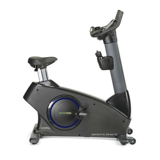
- Page 1 U1000g Upright Bike...
- Page 2 For your safety and benefit, please read this entire manual. Please keep the manual in a convenient place for quick reference when needed. BODYCRAFT offers a complete array of high quality fitness equipment. Please refer to our web site at www.bodycraft.com to view more ways to enhance your lifestyle.
-
Page 3: Table Of Contents
ABLE ONTENTS Product Safety ………………………….…………………………………………………… 3 Product Assembly ………………………………………………………………………….. 4 Hardware Identification Chart ……………………………………………………………… 5 Assembly Parts ……………………………………………….…………………………….. 6 Assembly Instructions ……………………………………………………………………… 7 Operational Instructions ………………………………………..….…. ……....11 Console Operation Instructions ………………………………………………………… Warm Up and Cool Down ……………………………………………………………….. Part List ………………………………………………..………………………………….. Exploded View ……………………………………….……………………………………... -
Page 4: Product Safety
RODUCT AFETY Basic precautions should always be followed, including the following safety instructions when using this equipment: WARNING: To reduce the risk of serious injury, read the following Safety Instructions before using the Upright Bike. 1. It is recommended that you perform warm up exercises before using this equipment. 2. -
Page 5: Product Assembly
RODUCT SSEMBLY Console Handlebar Hand Wrist Pad Pulse Seat Sensor Accessory Upright Post Tray Adjustment Pedal Main Frame Transportation Wheels Rear Stabilizer Leveler THE FOLLOWING TOOLS ARE INCLUDED FOR ASSEMBLY: SOCKET WRENCH T-HAND SOCKET COMBINATION (13mm) WRENCH (17mm) WRENCH (65mm) -
Page 6: Hardware Identification Chart
“H ARDWARE DENTIFICATION HART” Unpack the box in a clear area. Use the List of Hardware below to check the contents of the hardware kit. This chart is provided to help identify the hardware used in the assembly process. Place the washers, the end of bolts, or screws on the circles to check for the correct diameter. -
Page 7: Assembly Parts
SSEMBLY ARTS” Unpack the box in a clear area. Follow the List of Assembly Parts below to check and make sure all assembly parts are present and in good condition. Do not dispose of the packing material until the assembly process is completed. Assembly tools and hardware kit have included for you to use when assembling the product Front &... -
Page 8: Assembly Instructions
SSEMBLY NSTRUCTIONS” Place all parts from the box in a cleared area and position them on the floor in front of you. Remove all packing materials from your area and place them back into the box. Do not dispose of the packing materials until assembly is completed. - Page 9 SSEMBLY NSTRUCTIONS” NOTE: Do not remove the Nuts (135) during assembly. – TEP 3 Connection Wire Assembly Plug the Middle Connection Wire (113) into the Lower Connection Wire (114). Be careful not to pinch the wires. – TEP 4 Upright Post Assembly a.
- Page 10 “A SSEMBLY NSTRUCTIONS” – TEP 7 Console Bracket Assembly Attach the Front Console Bracket (127) and the Back Console Bracket (128) to the Upright Post Assembly (5) and fully secure with 4pcs Self-Tapping Screws, Truss Head (M4x20mm)(85) and 1pcs Bolt, Round Head (M5xp0.8x15mm)(87).
- Page 11 “A SSEMBLY NSTRUCTIONS” – TEP 9 Accessory Tray Assembly a. NOTE: For shipping purpose, 2pcs Bolts, Round Head (M5xp0.8x25mm)(88) are attached on the Upright Post Assembly (5). b. Place the Accessory Tray Support Pad (36) and Accessory Tray (37) on the Upright Post Assembly (5) and secure with 2pcs Bolts, Round Head (M5xp0.8x25mm)(88).
-
Page 12: Operational Instructions
” PERATIONAL NSTRUCTIONS” OW TO TRANSPORT THE BIKE SAFELY Hold the Rear Stabilizer (3) up with two hands and tow the item to the desired place carefully Make sure the floor is level while towing the item EAT POST ADJUSTMENT USER CAN ADJUST THE SEAT HEIGHT WHILE BE SEATED ... -
Page 13: Console Operation Instructions
“C ” ONSOLE PERATION NSTRUCTIONS Please read the console operation instruction thoroughly and get familiar with the console layout. Practice using this console before you start in order to get a better understanding of the functions. Below is the console layout and detailed operation instructions. - Page 14 Home key: Used to exit the current activities and go back home/idle mode. Displays Since this is an interactive display, therefore the screen will change according to with your finger tip’s touch. Follow the screen instruction to operate this console. Here are a few common screens you will see and their operations –...
- Page 15 o Just Go button: touch this button to jump start Quick Start program. The time will count up. You may adjust resistance level at any time or touch Cool Down button to end program and enter cool down. o Settings button: touch this button to see product record as well as changing the units system from English to Metric.
- Page 16 Basic Operation Power up: Since this is a self-generating product, user must pedal the product to power up the console. Pause a program: If a program is running and there is no RPM for a few seconds, the console will pause and stop accumulating data.
- Page 17 Workout Programs Besides Quick Start function, there are 9 program options as well as favorite programs for your selection: Manual, Random, Interval, Hill Climb, Strength, Target HR, HR Interval, Fat Burn, Cardio and Favorites. Quick Start: Pressing “GO” key or “Just Go” on screen during home screen/idle mode will quick start the console.
- Page 18 HR programs: The Heart Rate programs are designed to keep you training at the chosen heart rate level. These programs will only work when there is a valid heart rate signal. For the safety, the program is to start with a warm up session to get the heart rate up close to 20% of the target before it begins the heart rate training session.
- Page 19 Do not hold the hand pulse grips too tightly. Built in Wireless Heart Rate Receiver Note: Chest strap transmitter does not come with this unit; contact BODYCRAFT, or your dealer for purchase. This product is equipped with a built-in receiver for your heart rate monitoring. Any heart rate telemetry strap that transmits at 5Khz is compatible.
- Page 20 (Note: The transmitter is on automatically when being worn. It is off when it is not connected to your body. However, as moisture may activate the transmitter, thoroughly dry the transmitter to prolong battery life.) Erratic Heart Rate Readings: Erratic readings on the receiver can be caused by electromagnetic disturbances. If the heart rate readings appear to be abnormal, check that your product is not within range of other strong electromagnetic signals.
-
Page 21: Warm Up And Cool Down
“W ARM- P AND OOL- OWN” Warm-up The purpose of warming up is to prepare your body for exercise and to minimize injuries. Warm up for two to five minutes before strength-training or aerobic exercising. Perform activities that raise your heart rate and warm the working muscles. -
Page 22: Part List
ARTS IST” NO. Item Name Q'ty NO. Item Name Q'ty Main Frame Right Upright Post Sleeve Front Stabilizer Front Aluminum Upright Cover Rear Stabilizer Rear Aluminum Upright Cover Seat Post Air Pressure Bar Upright Post Seat Adjustment Lever Handlebar Fixed Stand Left Cover Spacer Right Cover... - Page 23 ” ARTS IST” NO. Item Name Q'ty NO. Item Name Q'ty Washer (10.6×60×2.0t) 121 Hybrid Generator Wire Washer (18.3×25×1.0t) 125 Spacer (4.6mm) Lock Washer (M6) 126 Spacer (36mm) Washer (21×30×1.0t) 127 Front Console Bracket Screw (M3×25mm) 128 Back Console Bracket Screw (M4×20mm) 129 Handlebar Plug (ψ31.8) Screw (M5×18mm)
-
Page 24: Exploded View
XPLODED... -
Page 26: Product Warranty
5. Any accessories not included in the original packaging. If the item exhibits such a defect, BODYCRAFT will, at its option, repair or replace it without cost for parts. Shipping and handling charges may apply. (BODYCRAFT may require return of the part(s) or photographic evidence of the damaged part(s) prior to replacement).
Need help?
Do you have a question about the U1000G and is the answer not in the manual?
Questions and answers