Table of Contents
Advertisement
Quick Links
INSTALLATION AND OPERATING MANUAL
ACR Recessed
Air Curtain
Electrically Heated, Ambient & LPHW
WARNINGS
Nortek Global HVAC (UK) Limited equipment must be installed and maintained in accordance with the
requirements of the Codes of Practice or rules in force. All external wiring MUST comply with the codes of practice
or rules in force in the country of installation.
Improper installation, adjustment, alteration, service or maintenance can cause property damage, injury or death.
Read instructions before installing or servicing this equipment. Gas-fired appliances are not designed for use in
hazardous atmospheres containing flammable vapours or combustible dust, containing chlorinated or halogenated
hydrocarbons, or in applications with airborne silicone substances.
Reznor® is a registered trademark of Nortek Global HVAC, LLC.
ErP
2018
Part No. D301051
Advertisement
Table of Contents

Related Manuals for Reznor ACR1000SE6-1PH


Summary of Contents for Reznor ACR1000SE6-1PH
- Page 1 Read instructions before installing or servicing this equipment. Gas-fired appliances are not designed for use in hazardous atmospheres containing flammable vapours or combustible dust, containing chlorinated or halogenated hydrocarbons, or in applications with airborne silicone substances. Reznor® is a registered trademark of Nortek Global HVAC, LLC. Part No. D301051 2018...
- Page 2 Introduction. elcome to the range of Airbloc ACR Recessed Air Curtains. Local regulations may vary in the country of use and it is the installers responsibility to ensure that such regulations are satisfied All installation and assembly procedures must be carried out by suitable competent persons. Commissioning and service procedures must be carried out by suitable qualified persons to the statutory regulations in the country of use.
-
Page 3: Table Of Contents
Document Index. Servicing & Maintenance Instructions Installation Requirements 1.1 Compliance Notice Spare Parts 1.2 Certificate of Conformity 7.1 General 1.3 General Product Information 7.2 Standard Controller 1.4 Model Definition 7.3 SmartElec3 Controller 1.5 General Requirements 7.4 Heating mediums 1.6 Health and Safety 1.7 Delivery and pre-installation Fault Finding Guide 1.8 Location... - Page 4 Document Index cont. 10.3.6.5 External Temperature Offset 10.3.6.6 Temperature Limits 10.3.7 Power-up Manual Reset 10.3.8 Air Curtain Addressing 10.3.9 Keypad Sequences (standard controller) 10.3.10 Keypad Sequences (SmartElec controller) Doc No. D301021 Page 4 of 64...
-
Page 5: Installation Requirements 6
Installation Requirements. the use of the appliance so as to ensure its continued safe and efficient use. Isolate any electrical supply to the heater and controller Nortek Global HVAC (UK) Ltd. have a commitment to before proceeding. continuous improvement and therefore reserves the right ... -
Page 6: Certificate Of Conformity 7
energy to the heating elements. This combined with the in- Certificates of conformity built intelligent sensor control, maintains a fixed outlet temperature, thereby reducing energy consumption as Certificates are available from the Quality Control Department compared to an air curtain without the SmartElec3 control. at Nortek Global HVAC (UK) Ltd. -
Page 7: General Requirements
General requirements Health and Safety Caution Warning Before installation, check that the local distribution conditions, Airbloc Air Curtains must be installed in accordance with any nature of gas and pressure, and the current state adjustment relevant and Regulations. Due account should be taken of any of the appliance are compatible. -
Page 8: Clearance Distance
Care must be taken to allow complete free air movement into Remote unit is wired to the base unit via a pre-wired cable the inlet grilles of the unit to ensure correct working operation fitted with RJ45 plugs. of the air curtain. The discharge opening should be as close to the top of the door as possible and to cover the entire door 1.10.2 SmartElec3 controller width. -
Page 9: Dimensions
Dimensions. ACR Air Curtain Fig.1 DIM 'C' DIM 'F' DIM 'G' DIM 'B' ACR1000SE6/9; ACR1500SE12; ACR2000SE18; ACR1200HE12; ACR1800HE18; ACR2000HE18; Size ACR1000SW9; ACR1500SW12; ACR2000SW18; ACR1200HW12; ACR1800HW18; ACR2000HW18; ACR1000SA ACR1500SA ACR2000SA ACR1200HA ACR1800HA ACR2000HA 1220 1520 2020 1185 1785 2097 1182 1482 1982 1150 1750... -
Page 10: Program Keypad 9
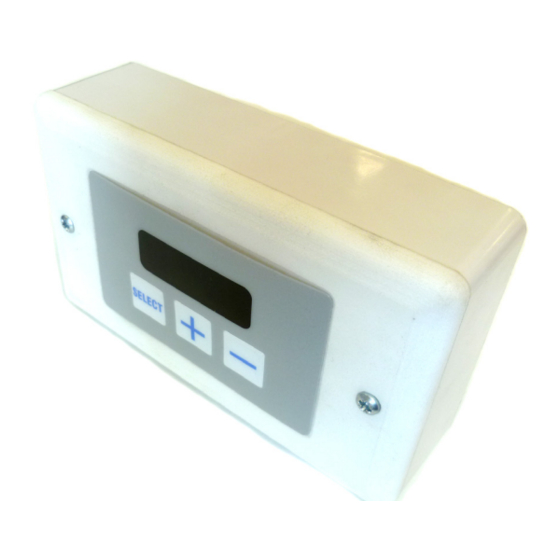
Program keypad dimensions The keypad is supplied with an industry standard plastic double surface mounted socket box. Alternatively the keypad can be flush mounted using a customer supplied metal flush box as shown below. Fig.2. Using surface mount box 120 crs Fig.3. -
Page 11: Technical Specifications
Technical Specifications. 3.1 (Single Phase only) ACR1000SE6-1PH ACR1500SE6-1PH ACR2000SE9-1PH General Data Maximum height Door width Heat Medium Electrical heated Heat settings 3 / 6 4.5 / 9 Fan type / dia Crossflow / 100mm Fan settings 3 Speeds Switching type... - Page 12 ACR1000SE9 ACR1500SE12 ACR2000SE18 General Data Maximum height Door width Heat Medium Electrical heated Heat settings 4.5 / 9 6 / 12 9 / 18 Fan type / dia Crossflow / 100mm Fan settings 3 speeds Switching type 3 tactile pushbuttons Weight 28.0 34.0...
- Page 13 ACR1200HE12 ACR1800HE18 ACR2000HE18 General Data Maximum height Door width Heat Medium Electrical heated Heat settings 6 / 12 9 / 18 Fan type / dia Crossflow / 100mm Fan settings 3 speeds Switching type 3 tactile pushbuttons Weight 38.0 55.0 63.0 Electrical Data Supply voltage...
- Page 14 ACR1000SA ACR1500SA ACR2000SA General Data Maximum height Door width Heat Medium Ambient Fan type / dia Crossflow / 100mm Fan settings Switching type 3 tactile pushbuttons Weight 28.0 34.0 49.0 Electrical Data Supply voltage 230V 1ph 50Hz Total load kW (a) 0.06 (0.26) 0.09 (0.4) Motor power...
- Page 15 ACR1200HA ACR1800HA ACR2000HA General Data Maximum height Door width Heat Medium Ambient Fan type / dia Crossflow / 100mm Fan settings Switching type 3 tactile pushbuttons Weight 38.0 55.0 63.0 Electrical Data Supply voltage 230V 1ph 50Hz Total load kW (a) 0.4 (1.61) Motor power Max Starting current*...
- Page 16 ACR1000SW9 ACR1500SW12 ACR2000SW18 General Data Maximum height Door width Heat Medium LPHW Heat settings Fan type / dia Crossflow / 100mm Fan settings Switching type 3 tactile pushbuttons Weight 28.0 34.0 49.0 Electrical Data Supply voltage 230V 1ph 50Hz Total load kW (a) 0.06 (0.26) 0.09 (0.4)
- Page 17 ACR1200HW12 ACR1800HW18 ACR2000HW18 General Data Maximum height Door width Heat Medium LPHW Heat settings Fan type / dia Crossflow / 100mm Fan settings Switching type 3 tactile pushbuttons Weight 38.0 55.0 63.0 Electrical Data Supply voltage 230V 1ph 50Hz Total load kW (a) 0.4 (1.6) Motor power...
- Page 18 Standard Program Controls General Data Sensor Input Protection 1 x 1A fuse for the protection of the fan switching devices. Fan Output 3 off Relay for High, Medium and Low Fan setting 3A max 230vac Screw terminals 4 for supply, 6 for elements output, 4 for fan output, 2 for BMS (time) control, 2 for sensor input, 2 for external thermal trip, 2 for ex- Connections ternal door switch, 2 for 0-10v fan option, 2 for 0-5v fault output, 2 for filter...
- Page 19 3.10 LPHW/Ambient Controls General Data Sensor Input Control Setpoint 16 to 35 ºC in steps of 1 degree Temperature Control 0-10v valve output (proportional) Cycle Time 2 seconds fixed Protection 1 x 1A fuse for the protection of the mains input Fan Output 3 off Relays for High, Medium and Low Fan setting 3A max 230Vac Screw terminals 3 for mains supply, 4 for fan output, 2 for BMS (time) control,...
-
Page 20: Wiring Diagrams
Wiring Diagrams. Installer Wiring - Electrically Heated 6 & 9kW SINGLE PHASE ONLY he program panel is connected to the base unit via a pre-wired RJ45 cable max length 100m. It is recommended that this cable is run separately within its own trunking to avoid external interference. - Page 21 Installer Wiring - Electrically Heated 9, 12 & 18kW THREE PHASE ONLY The program panel is connected to the base unit via a pre-wired RJ45 cable max length 100m. It is recommended that this cable is run separately within its own trunking to avoid external interference. External switch inputs (eg Timer) to be volt free and wired via normally open contacts to terminal pair marked ‘timer’...
- Page 22 Installer Wiring - Ambient The program panel is connected to the base unit via a pre-wired RJ45 cable max length 100m. It is recommended that this cable is run separately within its own trunking to avoid external interference. External switch inputs (eg Timer) to be volt free and wired via normally open contacts to terminal pair marked ‘timer’ (contacts closed to enable).
- Page 23 Installer Wiring - LPHW The program panel is connected to the base unit via a pre-wired RJ45 cable max length 100m. It is recommended that this cable is run separately within its own trunking to avoid external interference. External switch inputs (eg Timer) to be volt free and wired via normally open contacts to terminal pair marked ‘timer’ (contacts closed to enable).
- Page 24 Factory Wiring - Electrically heated ACR1000/ACR1500 6kW SINGLE PHASE ONLY R(B) L(M) L(B) R(M) L(T) Elements Fan Motor FACTORY INSTALLED EARTH LINK. DO NOT REMOVE 1 2 3 N CHASSIS EARTH BASE UNIT (located in air curtain) FAULT = OPTIONAL 5vDC OUTPUT FAN = OPTIONAL 10vDC FAN CONTROL OUTPUT RS485 Comms TEMP...
- Page 25 Factory Wiring - Electrically heated ACR2000 9kW SINGLE PHASE ONLY R(B) L(M) L(B) R(M) L(T) Elements Fan Motor FACTORY INSTALLED EARTH LINK. DO NOT REMOVE 1 2 3 N CHASSIS EARTH BASE UNIT (located in air curtain) FAULT = OPTIONAL 5vDC OUTPUT FAN = OPTIONAL 10vDC FAN CONTROL OUTPUT RS485 Comms FAULT...
- Page 26 Factory Wiring - Electrically heated ACR1000/ACR1500 9 & 12kW THREE PHASE ONLY Elements Fan Motor FACTORY INSTALLED EARTH LINK. DO NOT REMOVE 1 2 3 N CHASSIS EARTH BASE UNIT (located in air curtain) FAULT = OPTIONAL 5vDC OUTPUT FAN = OPTIONAL 10vDC FAN CONTROL OUTPUT RS485 Comms FAULT TIMER...
- Page 27 Factory Wiring - Electrically heated ACR1200/1800/2000 HE 12 & 18kW ACR 2000 SE 18kW THREE PHASE ONLY Elements FACTORY INSTALLED EARTH LINK. DO NOT REMOVE Fan Motor 1 2 3 N CHASSIS EARTH BASE UNIT (located in air curtain) FAULT = OPTIONAL 5vDC OUTPUT FAN = OPTIONAL 10vDC FAN CONTROL OUTPUT RS485 Comms FAULT...
- Page 28 Factory Wiring - Ambient ACR1000SA/ACR1500SA Fan Motor BASE UNIT FACTORY (located in air curtain) INSTALLED EARTH LINK. DO NOT REMOVE 1 2 3 N CHASSIS EARTH 0-10v OUTLET FILTER STAT RETURN VALVE PIPE FAULT TIMER DOOR 0-10v COLD 900656 IWL FACTORY INSTALLED SENSOR (EXT) OPTIONAL, DISCONNECT IF NOT...
- Page 29 4.10 Factory Wiring - Ambient ACR1200HA/ACR1800HA/ACR2000HA ACR2000SA BASE UNIT FACTORY (located in air curtain) INSTALLED EARTH LINK. DO NOT REMOVE Fan Motor 1 2 3 N CHASSIS EARTH OUTLET 0-10v STAT RETURN FILTER PIPE VALVE TIMER FAULT DOOR 0-10v COLD 900657 IWL FACTORY INSTALLED SENSOR (EXT) OPTIONAL,...
- Page 30 4.11 Factory Wiring - LPHW ACR1000SW/ACR1500SW Fan Motor BASE UNIT FACTORY (located in air curtain) INSTALLED EARTH LINK. DO NOT REMOVE 1 2 3 N CHASSIS EARTH OUTLET 0-10v FILTER STAT RETURN VALVE PIPE TIMER FAULT DOOR COLD 0-10v Sensor Sensor Sensor FACTORY INSTALLED...
- Page 31 4.12 Factory Wiring - LPHW ACR1200HW/ACR1800HW/ACR2000HW ACR2000SW18 BASE UNIT FACTORY (located in air curtain) INSTALLED EARTH LINK. DO NOT REMOVE Fan Motor 1 2 3 N CHASSIS EARTH OUTLET 0-10v FILTER STAT RETURN PIPE VALVE FAULT TIMER DOOR 0-10v COLD Sensor Sensor Sensor...
- Page 32 4.13 Network Wiring - Ambient/LPHW Programmer Networking Keypad This diagram refers only to the wiring of 2 or more networked air curtains. (maximum 16 air SELECT curtains per control panel). For mains wiring refer to section 4 of this manual ‘installer wiring details’.
- Page 33 4.14 Network Wiring - Electrically heated Networking This diagram refers only to the wiring of 2 or more networked air curtains. (maximum 16 air curtains per control panel). For mains wiring refer to section 4 of this manual ‘installer wiring details’.
- Page 34 4.15 Installer wiring SmartElec3 control. 415v 50Hz MAINS SUPPLY BASE UNIT (located in air curtain) CHASSIS EARTH 1 2 3 N FACTORY INSTALLED EARTH LINK. DO NOT REMOVE Comms RS485 TIMER DOOR TEMP STAT Programmer Keypad TIMER DOOR terminals as Optional Sensor supplied...
- Page 35 4.16 Factory Installed Wiring. ACR1000/ACR1500 with SmartElec3 Control. Fan motor FACTORY INSTALLED EARTH LINK. DO NOT REMOVE 1 2 3 N CHASSIS EARTH BASE UNIT (located in air curtain) Comms RS485 TIMER DOOR TEMP STAT 900653 IWL Sensor Optional Outlet Sensor Sensor Overheat 1...
- Page 36 4.17 Factory Installed Wiring. ACR1200/ACR1800HE/ACR2000HE with SmartElec3 Control Fan motor FACTORY INSTALLED EARTH LINK. DO NOT REMOVE 1 2 3 N CHASSIS EARTH BASE UNIT (located in air curtain) Comms RS485 TIMER DOOR TEMP STAT Sensor 900663 IWL Optional Outlet Sensor Sensor Overheat 1...
- Page 37 4.18 Network Wiring with SmartElec3 Control. BASE UNIT BASE UNIT (air curtain '0') (air curtain '1') terminals as supplied Comms Comms RS485 RS485 TIMER DOOR TIMER DOOR TIMER DOOR TEMP STAT TEMP STAT Sensor Sensor Optional Optional Sensor*** Sensor*** Door Door Switch** Switch**...
-
Page 38: Mounting
Installation Details. Mounting the points of attachment to the building are sound. Verification with the consultant/architect or owner of the building is recommended to ensure that a sound, irbloc units should be installed horizontally directly over mechanically stable installation can be achieved. the door opening. - Page 39 Step 3 Step 6 Access to the inside of the air curtain grille can be made. Open Either drop rods or catenary wire (available from the grille. The grille is hinged to prevent the inner frame from manufacturer) can be used to fasten the air curtain to the dropping.
-
Page 40: Program Keypad
After fitting the product in the ceiling recess and adjusting the Fig.5 Conduit box flush mounting height to ensure that the grille sits flush to the ceiling (when re-fitted) take the grille assembly and refit using the screws removed during Step 5. Program Keypad The Electronic base unit is pre-installed inside the air curtain. -
Page 41: Lphw Only
5.6 Installation details - LPHW only Fig. 6. Typical schematic of a 3 port valve system To avoid risk of transit damage to the flow and return connections, ON LPHW STANDARD CAPACITY ONLY the heating coil is provided loose inside the case together with the air deflector plate and side supports. -
Page 42: Installation Wiring
5.6.1 Three Port Valve An optional 3 port valve (supplied by others) can be used on the flow and return pipes to divert the hot water from the unit when not in use. The valve must be fitted in accordance with the manufacturers instructions. - Page 43 Service & Maintenance. Step 2 ALWAYS ENSURE THAT THE EXTERNAL MAINS ELECTRICITY SUPPLY IS SWITCHED OFF BEFORE COMMENCING Open the grille. The grille is hinged to prevent the inner frame ANY MAINTENANCE ON THIS HEATER from dropping. Access to the inside of the air curtain grille can be made.
-
Page 44: Standard Controller
Spare Parts. Note Any spare part components that are not approved by Nortek Global HVAC (UK) LTD could invalidate the approval of the appliance and invalidate the warranty. 7.1 General ACR1000SE06/ ACR1500SE06/ ACR2000SE09/ ACR1200HE12/ ACR1800HE18/ ACR1000SE09 ACR1500SE12/ ACR2000SE18/ Item Desc. -
Page 45: Smartelec3 Controller
7.3 SmartElec3 Controller Due to the nature of it’s construction, it is not advisable to repair damaged electronic components on either the SELEC3BU45 base unit or AC-ACRRP45 programmer Item Desc. All models Item Desc. All models Control Program 900473 108221-RJ45 Fuse Panel Outdoor... -
Page 46: Standard Controller
Fault Finding. been cleared. General f the air curtain does not operate after running through the Apart from the communication failure alarm which detail provided in Section 10, then a suitably competent could be due to a broken connection of the data link and air curtain not found alarm, which could be due to service engineer should be called to identify the nature of the... - Page 47 8.4.1 SmartElec3/Standard Fault Codes Air curtain address _ _, E5 and E6 codes also apply to standard controller. Code Description Symptom Possible Cause Remedy Bad data cable connection Check data cables and plugs # _ _ Communications failure No control on unit Damaged cable Replace damaged cable Air sensor cable disconnected...
- Page 48 Parts Replacement. Warning Ensure electrical power is isolated from the product. For access follow steps 1 - 4 as stated in Section 6 9.1 Electrical element replacement SE. Step 1 Using a 4mm Allen key slacken the M6 Allen screws at the side of the grille.
- Page 49 Step 4 Step 4 Lift out element cartridge, replace as required. Using a 2.5mm Allen key, slacken the rotor hub grub screw. Note: when refitting ensure that the grub screw bears on the flat of the motor shaft. 9.3 Rotor and motor replacement SE Step 1 Using a 4mm Allen key slacken the M6 Allen screws at the side of the grille.
- Page 50 Carefully hinge down the access plate. Note Take the weight as access plate swings down. Step 2 Remove 6 screws securing access panel and carefully remove panel. Step 8 Remove the four 10mm bolts securing the motor to its bracket. Step 3 Remove 8 bolts securing wheel assembly.
-
Page 51: Lphw Coil
Step 5 Step 8 Holding handle, carefully pull motor and air wheel assembly Disconnect the wires from the motor to the controller base forward. unit. Fan terminals (similar position on LPHW) Step 6 Remove screw securing rotor bearing plate. Step 9 Repeat for opposite side. - Page 52 Step 2 Disconnect flow/return connections with appropriate tools. Step 3 Remove the air deflector plate and the side support plates, retaining the screws. Step 4 Remove coil fixing screws from the outside of the air curtain body. Step 5 Withdraw the coil. Replace LPHW coil in reverse order.
-
Page 53: Keypad Buttons
10. User Instructions. ‘1’ denotes the AIR CURTAIN ADDRESS, and ‘27’ the current outlet temperature. 10.1 Standard Controller (electrically heated) If the display is set to ‘H1’ (half heat) then the display unit will show: The ‘dot’ after the air curtain number denotes heat setting 1. If the display is set to ‘H2’... -
Page 54: Door Link Settings
Press the buttons to increase/decrease the desired setting between C0, or 1-7 (see table below). If the air curtain is set to eg.: This will disappear after a period of 10 minutes of inactivity on the keypad. On pressing the button the display unit now works in the same way as standard for the fan and heat settings, but then an adjustable control temperature setting appears (if external... -
Page 55: Lphw/Ambient Controller
2. Re-scan/Engineers mode: ‘1’ denotes the air curtain address, and ‘27’ the current outlet temperature. Press and hold the button for two seconds, the display will go blank, then press The display will show the If the display is delivering power then the display will show: controller type in the first digit and the number of air curtains in the fourth digit. -
Page 56: Link-Group Interlock
10.2.4.3 All controllers is displayed as: ‘C’ interlocks Effect setting Timer/BMS interlock ‘1’ is the air curtain address and ‘d2’ denotes fan speed 2. Door interlock Press the buttons to increase/decrease the desired Stat interlock setting between d0, 1, 2, or 3. ‘L’... -
Page 57: Temperature Limits
10.2.4.6 Temperature Limits The next two displays eg: These show the permissible upper and lower limits for setting the external temperature sensor set point. This is useful for allowing the end user limited control over this setting. The maximum (default 35oC) may be set anywhere between the current minimum and 50oC, and the minimum (default 16oC) may be set anywhere between 3oC and the current maximum. -
Page 58: Keypad Buttons
10.3 Option SmartElec3 Controller During normal operation, press and hold the button for approximately two seconds. The display blanks until you release the button. The heating and fans are now turned off. Releasing the button in less than this time and the action has 10.3.1 Keypad buttons no effect. -
Page 59: Set Fan Speed
when it’s address appears on the display. 10.3.5 Set-up configurations The settings can then be changed as previously described. 10.3.5.1 Set fan speed 10.3.6 Engineers settings Once the display becomes illuminated press the the button once. Display shows the fan speed. Other options are available in engineer’s mode. -
Page 60: Link-Group Interlock
10.3.6.3 All controllers Heat OFF This function is accessed by pressing the button until the display shows 5°C Using this setting all air curtains in a network respond to the 10°C same settings. Settings for individual air curtains can still be changed if required. -
Page 61: Temperature Limits
will only work under the ’all controllers’ setting. Power-up Manual Reset. 10.3.6.6 Temperature limits This function is accessed by pressing the button until the display shows: respectively i.e. maximum and minimum set limits for set temperature. Use the buttons to change to the desired limit temperature settings. - Page 62 10.3.9 Keypad sequences (standard /LPHW) Standard - Normal display LPHW - Normal display LPHW - Normal set-up Standard - Normal set-up Standard - Engineers mode display LPHW - Engineers mode display Doc No. D301021 Page 62 of 64...
-
Page 63: Keypad Sequences (Smartelec Controller
LPHW - Engineers mode set-up Standard - Engineers mode set-up 10.3.10 Keypad sequences (SmartElec controller) Normal set-up Engineers mode display Doc No. D301021 Page 63 of 64... - Page 64 United Kingdom AFFIX AGENTS DETAILS HERE Tel: +44 (0) 1384 489 250 Fax: +44 (0) 1384 489 707 Email: reznorsales@nortek.com Web: www.reznor.eu/ Registered in England No˚ 1390934 Registered Office: The Colmore Building, 20 Colmore Circus Queensway, Birmingham, West Midlans, B4 6AT...
Need help?
Do you have a question about the ACR1000SE6-1PH and is the answer not in the manual?
Questions and answers