Table of Contents
Advertisement
UNIT HEATER INSTALLATION/OPERATION/MAINTENANCE
MODELS APD AND UDAP: STANDARD POWER VENT FAN TYPE
MODEL UDBP: STANDARD POWER VENT BLOWER TYPE
MODEL UDAS: SEPARATED-COMBUSTION FAN TYPE
MODEL UDBS: SEPARATED-COMBUSTION BLOWER TYPE
• Failure to follow safety warnings exactly could result in serious injury or property damage.
• Installation and service must be performed by a qualified installer, service agency, or the gas
supplier.
• Do not store or use gasoline or other flammable vapors and liquids in the vicinity of this or
any other appliance.
• Do not try to light any appliance.
• Do not touch any electrical switch; do not use any phone in your building.
• Leave the building immediately.
• Immediately call your gas supplier from a neighbor's phone. Follow the gas supplier's
instructions.
• If you cannot reach your gas supplier, call the fire department.
DO NOT DESTROY. PLEASE READ CAREFULLY. KEEP IN A SAFE PLACE FOR FUTURE REFERENCE.
Supersedes: D300519A (04-18) I-UDA&APD Series
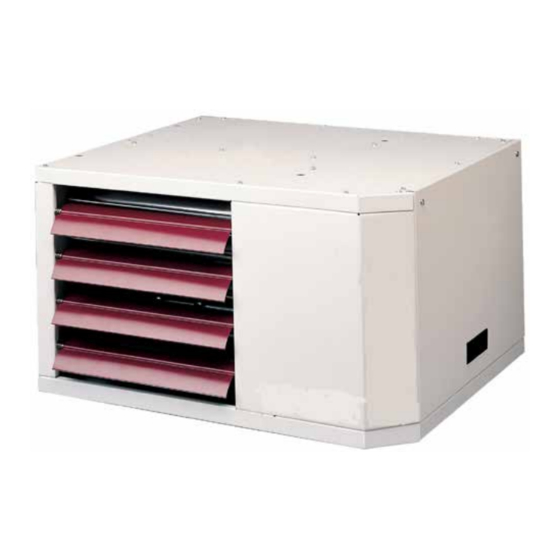
MODEL UDAP SHOWN
⚠ WARNING ⚠
FIRE OR EXPLOSION HAZARD
WHAT TO DO IF YOU SMELL GAS
Revision: I-UD&APD (04-19) PN195673R33
Advertisement
Table of Contents
Troubleshooting

Subscribe to Our Youtube Channel
Related Manuals for Reznor UDA Series


Summary of Contents for Reznor UDA Series
- Page 1 Revision: I-UD&APD (04-19) PN195673R33 Supersedes: D300519A (04-18) I-UDA&APD Series UNIT HEATER INSTALLATION/OPERATION/MAINTENANCE MODELS APD AND UDAP: STANDARD POWER VENT FAN TYPE MODEL UDBP: STANDARD POWER VENT BLOWER TYPE MODEL UDAS: SEPARATED-COMBUSTION FAN TYPE MODEL UDBS: SEPARATED-COMBUSTION BLOWER TYPE MODEL UDAP SHOWN ⚠...
-
Page 2: Table Of Contents
TABLE OF CONTENTS GENERAL INFORMATION ..............4 References . - Page 3 TABLE OF CONTENTS—CONTINUED OPERATION ................20 Component Descriptions .
-
Page 4: General Information
GENERAL INFORMATION This unit heater has been tested for capacity and efficiency so as to provide many years of safe and dependable comfort providing it is properly installed and maintained . With regular maintenance, this unit will operate satisfactorily year after year . Abuse, improper use, and/or improper maintenance can shorten the life of the appliance and create unsafe hazards . -
Page 5: Certification
⚠ WARNING ⚠ • Installation and service must be performed by a qualified installer, service agency, or the gas supplier. • Gas-fired appliances are not designed for use in hazardous atmospheres containing flammable vapors or combustible dust, in atmospheres containing chlorinated or halogenated hydrocarbons, or in applications with airborne silicone substances. -
Page 6: Unit Heater Location
UNIT HEATER LOCATION ⚠ CAUTION ⚠ Unit heaters should not be used in an application where the heated space temperature is below 50°F. Operating under low ambient conditions may cause condensation to form in the heat exchanger. Refer to the venting instructions listed in Table 1 for venting requirements and to the following sections of this manual to determine where to suspend the heater:... -
Page 7: Mounting Height Requirements
Table 3. Heater Throw Distances with Standard Horizontal Louvers at Mounting Heights of 1.5 to 5.5 Meters Distance Distance Distance Distance Distance Distance Unit Size 1 .5 1 .8 4 .3 9 .1 −21° 2 .1 4 .9 12 .2 −20° 2 .4 13 .8 −16°... -
Page 8: Hazards Of Chlorine
UNIT HEATER LOCATION—CONTINUED Hazards of Chlorine The presence of chlorine vapors in the combustion air of gas-fired heating equipment presents a potential corrosion hazard for separated-combustion heaters with regard to the combustion air inlet . Chlorine is usually found in the form of freon or degreaser vapors . - Page 9 Angular corner (available only on certain models) Hand pull (available only on certain models) Finger holes (available only on certain models) Figure 2. Dimensions—Models APD, UDAP, and UDBP (Refer to Table Table 6. Dimensions—Models UDAS and UDBS Dimension (See Figure Unit Size Inches (±1/16) (mm (±2))
-
Page 10: Weights
UNIT HEATER LOCATION—CONTINUED Clearances and Dimensions—Continued Figure 3. Dimensions—Models UDAS and UDBS (Refer to Table Weights ⚠ WARNING ⚠ Check the supporting structure to be used to verify that it has sufficient load carrying capacity to support the weight of the unit. Suspend the heater only from the threaded nut retainers or with a manufacturer-provided kit. -
Page 11: Combustion Air Requirements
Combustion Air Requirements Combustion air—models UDAS and UDBS Refer to the combustion air requirements in the venting instructions (refer to Table 1) for models UDAS and UDBS . Combustion air—models APD, UDAP, and UDBP ⚠ WARNING ⚠ Unit heater models APD, UDAP, and UDBP are designed to take combustion air from the space in which the unit is installed and are not designed for connection to outside combustion air intake ducts. -
Page 12: Acoustical Considerations
UNIT HEATER LOCATION—CONTINUED Acoustical Considerations Refer to sound level data in the APPENDIX: Technical Data when determining unit location based on acoustical considerations . UNCRATING, INSPECTING, AND PREPARATION FOR INSTALLATION Uncrating It is important to note when uncrating the unit that shipping brackets are attached with cabinet screws . When removing shipping brackets, re-insert ALL screws into the cabinet . -
Page 13: Downturn Nozzle Kits (Option Cd2, Cd3, Or Cd4)
Downturn nozzle kits (option CD2, CD3, or CD4) Application-specific downturn nozzle kits require four-point suspension . Follow the instructions provided with the kit Figure 5 Table to install . The additional length of the nozzle beyond the front of the unit is shown in and listed in Figure 5. -
Page 14: Lifting And Suspension Of Heater
HEATER INSTALLATION—CONTINUED Lifting and Suspension of Heater ⚠ CAUTION ⚠ • Before lifting the heater, verify that any screws used for holding shipping brackets were re- installed in the cabinet. • Before lifting heater model UDAS or UDBS, any unused suspension points on the control side of the heater MUST be plugged. -
Page 15: Piping Installation
PIPING INSTALLATION Gas Supply Pressure ⚠ WARNING ⚠ This appliance is equipped for a maximum gas supply pressure of 1/2 psi, 3.5 kPa, or 14 IN WC. A supply pressure greater than 1/2 psi requires the installation of an additional lockup-type service regulator external to the unit. -
Page 16: Gas Connections
PIPING INSTALLATION—CONTINUED Gas Connections ⚠ CAUTION ⚠ Pipe joint compounds (pipe dope) shall be resistant to the action of liquefied petroleum gas or any other chemical constituents of the gas being supplied. The gas connection is made at the pipe nipple that extends outside the cabinet . The connection size is either 1/2- or Table 10 . -
Page 17: Supply Wiring
Supply Wiring Check the rating plate on the heater for the supply voltage and current requirements . A dedicated line voltage supply with a disconnect switch should be run directly from the main electrical panel to the heater . All external wiring must be within approved conduit and have a minimum temperature rise rating of 60°C . -
Page 18: Wiring Diagrams
WIRING INSTALLATION—CONTINUED Wiring Diagrams Typical wiring diagrams are shown in Figure 13 Figure 14 . Figure 13. Typical Wiring Diagram—Single-Stage Models I-UD&APD (04-19) PN195673R33... - Page 19 NOTE: Two-stage valve circuit is NOT available on all models. Figure 14. Typical Wiring Diagram—Two-Stage Models I-UD&APD (04-19) PN195673R33...
-
Page 20: Operation
OPERATION Component Descriptions NOTE: Refer to the Troubleshooting section for probable causes and reset instructions for the following components. Pressure (combustion air proving) switch ⚠ DANGER ⚠ Safe operation of this unit requires proper venting flow. NEVER bypass the combustion air proving switch or attempt to operate the unit without the venter running and the proper flow in the vent system. -
Page 21: High Temperature Limit Control
Table 11. Pressure Switch Settings Models APD, UDAP, and UDBP Negative Pressure (IN WC) Unit Size Label Color Switch PN Startup Cold Equilibrium Hot Setpoint OFF Setpoint ON 1 .0 0 .8 0 .4 0 .6 Green 197030 1 .0 0 .8 0 .4 0 .6... -
Page 22: Interlock Door Switch (Models Udas And Udbs)
OPERATION—CONTINUED Component Descriptions—Continued Interlock door switch (models UDAS and UDBS) All sizes of heater model UDAS and UDBS are equipped with an interlock door switch (see Figure 15 for location) that prevents the heater from operating when the service door panel is open . The service panel is equipped with a pliable gasket that fully seals the door to provide added protection to prevent building air from entering the combustion zone of the heater . -
Page 23: Circuit Board (Dsi Integrated Control Module)
Figure 16. Novar® MINio Control Module Option D10 includes the controller and the sensor, which is field-mounted at the heater discharge . Option D14 requires a field-supplied sensor that is compatible with the control . For regulatory compliance specifications and safety precautions, review the control manufacturer’s installation instructions in the owner’s envelope . -
Page 24: Operating Sequence
OPERATION—CONTINUED Component Descriptions—Continued Circuit board (DSI integrated control module)—continued Table 12. Circuit Board (DSI Integrated Control Module) LEDs LED Type (Color) LED Status Indication Steady ON Normal operation, no call for heat Fast flash Normal operation, call for heat One flash System lockout, failed to detect or sustain flame Control (green) Two flashes... -
Page 25: Abnormal Heat Cycle Functions
Table 13. Normal Heat Cycle Operating Sequence —Continued Step Condition Action Limit switch is closed Pressure switch is closed Control continuously monitors inputs Flame is established 5 . Steady Thermostat call for heat heat remains Thermostat call for heat is Control deenergizes gas valve and proceeds to steps 6 and 7 removed 6 . -
Page 26: Fault Modes
OPERATION—CONTINUED Abnormal Heat Cycle Functions—Continued Table 14. Abnormal Heat Cycle Functions —Continued Abnormal Condition Action Function Venter motor runs through 2-second pressure switch recognition delay Control deenergizes gas valve Pressure switch opens before trial for ignition period Control runs venter motor through post-purge period Control restarts heat cycle at pressure switch proving state if call for heat still exists Pressure switch opens for less than 2 seconds during trial for ignition period... -
Page 27: Startup
Startup Pre-startup checklist Check the following before startup: ‰ Check to ensure that all screws used to secure shipping brackets have been re-installed in heater cabinet ‰ Check suspension—unit must be secure and level Table 4 ‰ Check to ensure that clearances from combustibles are in accordance with Table 1 ‰... - Page 28 OPERATION—CONTINUED Startup—Continued Startup sequence—continued Startup the heater as follows: 1 . Set thermostat at lowest setting . 2 . Turn OFF all electric power to appliance . NOTE: This appliance is equipped with an ignition device that automatically lights the burner. Do not try to light the burner by hand.
-
Page 29: Post-Startup Checklist
Post-startup checklist Check the following after startup: ‰ Vent system testing procedure: perform the following steps for each heater or utility heater connected to the venting system and placed in operation while any other appliance(s) connected to the venting system(s) is not in operation: a . -
Page 30: Manifold Pressure Adjustment
OPERATION—CONTINUED Adjustments—Continued Manifold pressure adjustment If the heater is being installed at an elevation above 6,000 feet (1,830 meters), replace the pressure switch in accordance with the Pressure switch replacement section and then adjust the manifold pressure in accordance with the High-altitude deration section . -
Page 31: High-Altitude Deration
5 . If manometer reading does not indicate that valve outlet pressure is in accordance with Table 16, remove cap from regulator screw(s) (see Figure 19) and adjust pressure by turning regulator screw IN (clockwise) to increase pressure or OUT (counterclockwise) to decrease pressure . 6 . - Page 32 OPERATION—CONTINUED Adjustments—Continued High-altitude deration—continued NOTE: A manometer (fluid-filled gauge) is recommended rather than a spring-type gauge due to the difficulty of maintaining the calibration of a spring-type gauge. Use a water column manometer that is readable to the nearest tenth of an inch. Figure 19) .
- Page 33 Table 17. Inputs and Capacities by Altitude in US —Continued Altitude Normal Thermal Output Minimum Normal Thermal Output Minimum Input Capacity Input Input Capacity Input Feet Meters (BTUh) (BTUh) (BTUh) (BTUh) (BTUh) (BTUh) Unit Size 0–2000 0–610 60,000 49,800 42,000 75,000 62,250 52,500...
-
Page 34: Pressure Switch Replacement
OPERATION—CONTINUED Adjustments—Continued High-altitude deration—continued Table 17. Inputs and Capacities by Altitude in US —Continued Altitude Normal Thermal Output Minimum Normal Thermal Output Minimum Input Capacity Input Input Capacity Input Feet Meters (BTUh) (BTUh) (BTUh) (BTUh) (BTUh) (BTUh) Unit Size 0–2000 0–610 350,000 290,500... -
Page 35: Maintenance And Service
1 . Locate pressure switch in control compartment (see Figure 15) and mark and disconnect two pressure switch wires . 2 . Mark and disconnect sensing tube(s) from pressure switch . 3 . Remove two screws that secure mounting bracket and remove bracket and pressure switch . Save bracket and screws for reuse . -
Page 36: Burner Maintenance
MAINTENANCE AND SERVICE—CONTINUED Maintenance Procedures—Continued Burner maintenance Visually inspect the burner compartment (see Figure 21) . If there is an accumulation of dirt, dust, and/or lint, clean the compartment and remove and clean the burner as follows . Figure 21. Burner Assembly (Typical View Shown) ⚠... -
Page 37: Burner Orifice Maintenance
8 . Locate burner body supports (depending on size, burner will have two or more supports . 9 . At each support, remove one screw that secures support to secondary air shield . 10 . Holding venturi tube, slide entire burner assembly slightly to right to disengage burner from supports on left . 11 . -
Page 38: Ignition System Maintenance
MAINTENANCE AND SERVICE—CONTINUED Maintenance Procedures—Continued Ignition system maintenance • The DSI integrated control module (circuit board, see Figure 12) monitors the operation of the heater including ignition . The only replaceable component is the 3-amp Type ATC or ATO fuse (color code: violet, PN 201685) . If the fuse is blown, the problem is most likely an external overload . -
Page 39: Maintenance Of Venter Motor And Wheel Assembly
Blade Sizes 30-250 Motor Setscrew Sizes Blade 300-400 Motor Setscrew Figure 23. Fan Blade Positioning and Spacing Table 19. Fan Blade Spacing Dimension A Setscrew Torque Standard Wire Fan Guard Option AZ8 Wire Fan Guard Unit Size (Inch-Pounds with 0.5 Inch (13 mm) Spacing with 0.334 Inch (8.5 mm) Spacing (±10)) Inches... -
Page 40: Operating Gas Valve Maintenance
MAINTENANCE AND SERVICE—CONTINUED Maintenance Procedures—Continued Maintenance of venter motor and wheel assembly—continued 5 . While holding venter motor, remove three or four screws that secure venter motor mounting plate to venter housing . Remove motor and wheel assembly from heater . 6 . -
Page 41: Pressure (Combustion Air) Switch Maintenance
Pressure (combustion air) switch maintenance Figure 20) needs replacing, use only the factory-authorized replacement If it is determined that the pressure switch (see part that is designed for the model and size of heater being serviced . Replace the switch in accordance with the Pressure switch replacement section . -
Page 42: Door Switch Maintenance (Models Udas And Udbs Only)
MAINTENANCE AND SERVICE—CONTINUED Maintenance Procedures—Continued Interlock door switch maintenance (models UDAS and UDBS only) If it is determined that the interlock door switch (see Figure 25) needs replacing, use only a factory-authorized Figure 15 . replacement part that is designed for the heater . For the approximate door switch location, see Transformer maintenance Figure 25) . - Page 43 I-UD&APD (04-19) PN195673R33...
-
Page 44: General Troubleshooting
TROUBLESHOOTING—CONTINUED General Troubleshooting Table 20 Refer to for general troubleshooting symptoms, probable causes, and remedies . Table 20. General Troubleshooting Symptom Probable Cause Remedy Venter motor 1 . No power to unit Turn ON power and check supply fuses or circuit breaker will not start 2 . - Page 45 Table 20. General Troubleshooting —Continued Symptom Probable Cause Remedy Burner cycles 1 . Gas pressure too high or too low Supply pressure should be 5–14 IN WC for natural gas or 11–14 IN WC for propane ON and OFF 2 . Burner not grounded Ensure that integrated circuit board is grounded (terminals P1–9) 3 .
-
Page 46: Appendix: Technical Data
APPENDIX: TECHNICAL DATA The data in the following tables applies to all models unless otherwise indicated . Technical Data (Unit Sizes 030–125) Unit Size Unit of Parameter Measurement BTUh 30,000 45,000 60,000 75,000 105,000 120,000 Input heating capacity 8 .8 13 .2 17 .6 22 .0... - Page 47 Technical Data (Unit Sizes 150–400) Unit Size Unit of Parameter Measurement BTUh 150,000 175,000 200,000 225,000 250,000 300,000 350,000 400,000 Input heating capacity 43 .9 51 .2 58 .6 65 .9 73 .2 87 .8 102 .5 117 .1 Thermal efficiency BTUh 124,500 145,250 166,000 186,750 207,500 249,000 290,500 332,000 Output heating capacity...
- Page 48 INSTALLATION RECORD—to be completed by the installer: Installer: Name ________________________________________________________ Company ________________________________________________________ Address ________________________________________________________ ________________________________________________________ ________________________________________________________ Phone _________________________________ Distributor (company from which the unit was purchased): Company ________________________________________________________ Contact ________________________________________________________ Address ________________________________________________________ ________________________________________________________ ________________________________________________________ Phone _________________________________ Model ________________ Serial No.______________________________Date of Installation ____________ SPECIFIC INSTALLATION NOTES: (i.e.
Need help?
Do you have a question about the UDA Series and is the answer not in the manual?
Questions and answers