Nibe SMO 40 Installer Manual
Control module
Hide thumbs
Also See for SMO 40:
- User manual (93 pages) ,
- Installer manual (80 pages) ,
- Installer manual (52 pages)
Table of Contents
Advertisement
Quick Links
Advertisement
Table of Contents

Related Manuals for Nibe SMO 40


Summary of Contents for Nibe SMO 40
- Page 1 Installer manual SMO 40 Control module IHB EN 1746-5 231760...
- Page 2 MY INSTALLATION INFO To temporarily increase the amount of hot water (if a hot water heater is installed to your SMO 40), first turn the control knob to mark menu 2 (water droplet) and then press the OK button twice.
-
Page 3: Table Of Contents
Component positions Electrical components 12 Technical data Dimensions 4 Pipe connections Technical specifications General Energy labelling Compatible NIBE air/water heat pumps Electrical circuit diagram Symbol key Temperature sensor installation on pipe Item register Docking alternatives Contact information 5 Electrical connections... -
Page 4: Important Information
©NIBE 2017. Danger to person or machine. NOTE Read the User Manual. SMO 40 must be installed via an isolator switch with a minimum breaking gap of 3 mm. NOTE If the supply cable is damaged, only NIBE, its service representat-... - Page 5 Improper disposal of the product by the user results in administrative penalties in accordance with current legis- lation. Caution You need the product's (14 digit) serial number for servicing and support. SMO 40 Chapter 1 | Important information...
- Page 6 Shuttle valve AUX1 AUX2 AUX3 AUX4 AUX5 AUX6 AA3-X7 Dipswitch Miscellaneous Checking additional heater Checking the function of the reversing valve Checking charge pump function Completed installation check of heat pump and associated equipment Chapter 1 | Important information SMO 40...
-
Page 7: Delivery And Handling
Aluminium tape Cable ties Heating pipe paste Current sensor Use all mounting points and install SMO 40 upright flat against the wall without any part of the control module Installatörshandbok SMO 40 protruding out beyond the edge of the wall. -
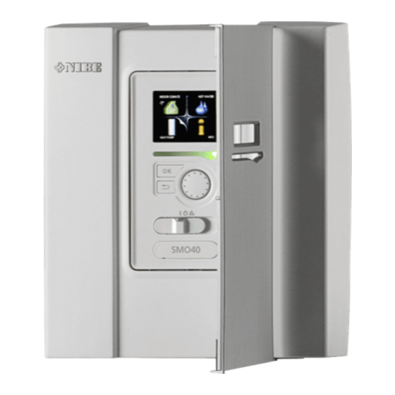
Page 8: The Control Module Design
Terminal block, AUX4 - AUX6 Switch AA4-XJ4 Serial number plate Cable grommet, incoming supply electricity, power for accessories Cable gland, signal Designations in component locations according to standard IEC 81346-1 and 81346-2. Chapter 3 | The Control Module Design SMO 40... -
Page 9: Pipe Connections
Symbol key Pipe installation must be carried out in accordance with Symbol Meaning current norms and directives. See manual for compatible NIBE air/water heat pump for installation of the heat Shut-off valve pump. Tapping valve Compatible NIBE air/water heat Trim valve... -
Page 10: Temperature Sensor Installation On Pipe
Temperature sensor installation Docking alternatives on pipe SMO 40 can be connected with other products from NIBE in several different ways, some of which are shown below (accessories may be required). Further option information is available at www.nibe.eu and in the respective assembly instructions for the ac- cessories used. - Page 11 AA25 Unit box with accessory card 2) Included in and supplied accessory Temperature sensor, return line 3) Included in and supplied NIBE heat pump (can vary depending on heat pump). BT12 Temperature sensor, condenser supply line Designations according to standards 81346-1 and 81346-...
- Page 12 Compatible NIBE air/water heat pump together with SMO 40 – docking step-controlled additional heat before the reversing valve for hot water -AA25 -RN10 -AA25-QN10 -EB1 -EB1 -FL2 -AA25 -KA1 -BT63 -CM1 -CP10 -AA25-BT7 -AA25 -BT1 -AA25-BT6 -EB101 -FL10 -QM31 -BT12...
- Page 13 Compatible NIBE air/water heat pump together with SMO 40 – docking step-controlled additional heat after reversing valve for hot water and accessory for extra climate system, pool and cooling -EP21 -AA25 -BT2 -GP20 -EB1 -EB1 -BT3 -QN25 -KA1 -AA25 -CP5...
- Page 14 Compatible NIBE air/water heat pumps together with SMO 40 and electric heater after reversing valve for hot water as well as pool and extra climate system (floating condensing) -EQ1 -EP22 -EB1 -AA25 -FL10 -AA25 -BT2 -BT64 -CM5 -GP20 -EB1 -BT3...
-
Page 15: Electrical Connections
If the building is equipped with an earth-fault breaker, ■ SMO 40 should be equipped with a separate one. SMO 40 must be installed via a circuit breaker with a ■ minimum breaking gap of 3 mm. For the electrical wiring diagram for the control mod- ■... -
Page 16: Accessibility, Electrical Connection
Torx 25 screwdriver. Lift the display unit from its mountings. Align the two lower mountings on the reverse of the display unit with the two upper holes in the panel as illustrated. Chapter 5 | Electrical connections SMO 40... -
Page 17: Cable Lock
5. When the electrical connection is ready the display must be reinstalled with three mounting points again, otherwise the front cover cannot be installed. Terminal block 3,5 mm 1 mm 3,5 mm 1 mm SMO 40 Chapter 5 | Electrical connections... -
Page 18: Connections
20 cm from high voltage cables. EB101-GP12 Power connection AA2-X4 SMO 40 must be installed via an isolator switch with a minimum breaking gap of 3mm. Minimum cable area AA2-X4 must be sized according to the fuse rating used. SMO 40... - Page 19 Connect the heat pump (EB101) with a screened three core cable to terminal block X4:1 (A), X4:2 (B) and X4:3 (GND) on the accessory board (AA5) as illustrated. If several heat pumps are to be connected to SMO 40 these must be connected in cascade as illustrated. NOTE Up to 8 heat pumps can be controlled by SMO 40.
- Page 20 F2040 F2040 AA5-X4 AA23-X4 AA23-X4 -X10 F2030 F2030 F2016/F2026 F2016/F2026 F2015/F2020/F2025/F2300 F2015/F2020/F2025/F2300 AA21-J2 AA21-J2 F2120 F2120 SMO 40 AA5-X4 Chapter 5 | Electrical connections SMO 40...
- Page 21 Temperature sensor, hot water top A temperature sensor for hot water top (BT7) can be connected to SMO 40 to show the water temperature at the top of the tank (if it is possible to install a sensor at the top of the tank).
-
Page 22: Optional Connections
The multi-core cable between the enclosure and SMO 40 must have a cable area of at least 0.5 mm². Connect the cable to the input board (AA3) on terminal block X4:1-4 where X4:1 is the common terminal block for the three current sensors. - Page 23 Room sensor Step controlled additional heat SMO 40 comes with a room sensor (BT50). The room NOTE sensor has a number of functions: Mark up any junction boxes with warnings for 1. Shows current room temperature in the control module display.
- Page 24 (if they are to aid with heating. connected). the circulation pumps (EB101-GP12 and EB102-GP12) SMO 40 controls a shunt valve and start signal to the ■ additional heating using three relays. If the installation external circulation pump (GP10) ■...
- Page 25 SMO 40 Caution Externt External If an external switch contact function is connec- ted to SMO 40, the function for use input or output must be selected in menu 5.4. GP10 Selectable inputs on the input board (AA3) for these AA2-X4 functions are AUX1 (X6:9-10), AUX2 (X6:11-12) and AUX3 (X6:13-14).
- Page 26 (very low price) with the sensor supply line cooling (BT64) must be connected electricity supplier (effect on the system is settable in to SMO 40. This option is only shown if the cooling menu 4.1.5). function in the heat pump has been activated.
- Page 27 5.4. The common alarm is preselected at the factory. NOTE If terminal block X7 is activated as the common alarm indicator, an accessory board may be required for additional functions. (see page 54). SMO 40 Chapter 5 | Electrical connections...
- Page 28 The reversing valve for cooling is connected to the AUX output, as illustrated below. Externt External AA3-X7 SMO 40 AA3-X7 Caution The relay outputs may be subjected to a max load of 2 A at resistive load (230V AC). Chapter 5 | Electrical connections SMO 40...
-
Page 29: Connecting Accessories
X4:9-12 on installation instructions provided. See page 54 for a list the input board AA3. Use cable type LiYY, EKKX or of those accessories that can be used for SMO 40. equivalent. Refer to the accessory manual for further instructions. -
Page 30: Commissioning And Adjusting
– "Start-up and inspection". SMO 40 1. Power the heat pump. 2. Power SMO 40. 3. Follow the start guide in the display on SMO 40 al- ternatively start the start guide in menu 5.7. Commissioning with additional heating only At first start follow the start guide, otherwise follow the list below. -
Page 31: Start Guide
There must be water in the climate system be- fore the switch is set to " ". 1. Set switch (SF1) on SMO 40 to position " ". 2. Follow the instructions in the display's start guide. If the start guide does not start when you start the SMO 40, start it manually in menu 5.7. -
Page 32: Control - Introduction
The control knob can be turned to the right or left. You can: ■ scroll in menus and between options. ■ increase and decrease the values. ■ change page in multiple page instructions (for example help text and service info). Chapter 7 | Control - Introduction SMO 40... -
Page 33: Menu System
This symbol indicates whether "holiday This menu only appears if a water heater is installed in setting" is active in 4.7. the system. This symbol indicates whether SMO 40 has Menu 3 - INFO contact with Uplink. Display of temperature and other operating information and access to the alarm log. - Page 34 Back button. marked. 2. Press the OK button to skip between the steps in the start guide. If the start guide is left on this page it closes automatically in 60 min Chapter 7 | Control - Introduction SMO 40...
- Page 35 1. Use the control knob to select the help symbol. 2. Press the OK button. The help text often consists of several windows that you can scroll between using the control knob. SMO 40 Chapter 7 | Control - Introduction...
-
Page 36: Control
1.9.5 - cooling settings * 1.9.6 - fan return time * 1.9.7 - own curve 1.9.7.1 - heating 1.9.7.2 - cooling ** 1.9.8 - point offset * Accessories are needed. ** Heat pump with cooling function required. Chapter 8 | Control SMO 40... -
Page 37: Menu 2 - Hot Water
2.9.2 - hot water recirc. * Menu 3 - INFO 3 - INFO 3.1 - service info 3.2 - compressor info 3.3 - add. heat info 3.4 - alarm log 3.5 - indoor temp. log * Accessories are needed. SMO 40 Chapter 8 | Control... -
Page 38: Menu 4 - My System
4.9 - advanced 4.9.1 - op. prioritisation 4.9.2 - auto mode setting 4.9.3 - degree minute setting 4.9.4 - factory setting user 4.9.5 - schedule blocking 4.9.6 - schedule silent mode * Accessories are needed. Chapter 8 | Control SMO 40... -
Page 39: Menu 5 - Service
5.11.1 - EB101 5.11.1.1 - heat pump 5.11.1.2 - charge pump (GP12) 5.11.2 - EB102 5.11.3 - EB103 5.11.4 - EB104 5.11.5 - EB105 5.11.6 - EB106 5.11.7 - EB107 5.11.8 - EB108 5.12 - country SMO 40 Chapter 8 | Control... - Page 40 Here you set the maximum permitted difference between the calculated and actual supply temperature Factory setting stop temp. lux: 53 °C during compressor respectively add. heat mode. Max diff. additional heat can never exceed max diff. com- pressor Chapter 8 | Control SMO 40...
- Page 41 Factory setting: 16 A Select whether step controlled or shunt controlled addi- tional heat is connected. Then you can make settings for transformation ratio the different alternatives. Setting range: 300 - 3000 Factory setting: 300 SMO 40 Chapter 8 | Control...
- Page 42 Set when the addition is to start, the minimum run time NOTE and the minimum temperature for external addition This menu is only displayed if SMO 40 is connec- with shunt here. External addition with shunt is for ex- ted to a heat pump with inverter controlled ample a wood/oil/gas/pellet boiler.
- Page 43 If the water heater is connected to SMO 40 hot water Slave (heat pump) Workspace for docking charging must be activated here. There are two ways of activating connected accessories. docking5.2.3 You can either mark the alternative in the list or use the automatic function "search installed acc.".
- Page 44 See the accessory installation instructions for function description. Chapter 8 | Control SMO 40...
- Page 45 Activated if mixer valve is installed and it is to be controlled from SMO 40. When the option is active, you can set the outgoing hot water temperature, shunt amplification and shunt waiting time for the mixer valve.
- Page 46 The heat pump must also be activated flow sensor for cooling operation. Setting option: EMK 500, EMK 300 / 310, EMK 150 Factory setting: EMK 500 Here you select which flow sensor is used for the energy measurement. Chapter 8 | Control SMO 40...
- Page 47 Make settings for the installed slaves here. Menu 5.11.1.1 - heat pump Make settings for the installed slave here. To see what settings you can make, see installation manual for the relevant installed slave. SMO 40 Chapter 8 | Control...
- Page 48 Set the operating mode for the charge pump here. play or program updating. auto: The charge pump runs according to the current operating mode for SMO 40. intermittent: The charge pump starts and stops 20 seconds before and after the compressor in the heat pump.
-
Page 49: Service
(°C) (kOhm) Servicing should only be carried out by persons 351.0 3.256 with the necessary expertise. 251.6 3.240 When replacing components on SMO 40 only 182.5 3.218 replacement parts from NIBE may be used. 133.8 3.189 99.22 3.150 Emergency mode 74.32... - Page 50 Menu 7.1 - update firmware update firmware7.1 start updating choose another file This allows you to update the software in SMO 40. NOTE For the following functions to work the USB The display unit is equipped with a USB socket that can...
- Page 51 Setting range: 1 s – 60 min Factory setting range: 5 s Here you can choose how current measurement values from SMO 40 should be saved onto a log file on the USB memory. 1. Set the desired interval between loggings.
-
Page 52: Disturbances In Comfort
Check any external switches. – If the operational interference is not shown in the display the following tips can be used: Air in the climate system. ■ Vent the climate system. – Chapter 10 | Disturbances in comfort SMO 40... -
Page 53: Additional Heating Only
– In event of repeated filling, contact the installer. The compressor does not start There is no heating requirement. ■ SMO 40 does not call on heating or hot water. – Compressor blocked due to the temperature condi- ■ tions. -
Page 54: Accessories
DUC (computer sub-centre) in the building. An accessory board is required if for example an HWC pump Communication is then performed using MODBUS-RTU. is to be connected to SMO 40 at the same time that the Part no 067 144 common alarm indication is activated. - Page 55 Part no. 018 090 ELK 42 Pool heating POOL 40 42 kW, 3 x 400 V POOL 40 is used to enable pool heating with SMO 40. Part no. 067 075 Part no 067 062 Extra shunt group ECS 40/ECS 41...
- Page 56 Part no. 083 220 Copper Part no. 083 231 VPB 1000 Copper Part no. 083 240 VPAS Water heater with double-jacketed vessel and solar coil. VPAS 300/450 Copper Part no. 087 720 Enamel Part no. 087 710 Chapter 11 | Accessories SMO 40...
-
Page 57: Technical Data
12 Technical data Dimensions SMO 40 Chapter 12 | Technical data... -
Page 58: Technical Specifications
Technical specifications IP 21 SMO 40 Electrical data Supply voltage 230V~ 50Hz Enclosure class IP21 Rated value for impulse voltage Pollution degree Fuse Optional connections Max number air/water heat pumps Max number of sensors Max number of charge pumps with internal accessory cards... -
Page 59: Energy Labelling
Energy labelling Supplier NIBE Model SMO 40 + F2030 / F2300 SMO 40 + F2040 / F2120 Controller, class Controller, contribution to efficiency SMO 40 Chapter 12 | Technical data... -
Page 60: Electrical Circuit Diagram
Electrical circuit diagram Chapter 12 | Technical data SMO 40... - Page 61 SMO 40 Chapter 12 | Technical data...
- Page 62 Chapter 12 | Technical data SMO 40...
- Page 63 SMO 40 Chapter 12 | Technical data...
- Page 64 Chapter 12 | Technical data SMO 40...
- Page 65 SMO 40 Chapter 12 | Technical data...
-
Page 66: Item Register
Commissioning and adjusting, 30 Shunt controlled additional heat, 24 Commissioning with additional heating only, 30 Step controlled additional heat, 23 Commissioning with NIBE air/water heat pump, 30 Temperature sensor, external flow line, 21 Cooling mode, 30 Temperature sensor, external return line, 21... - Page 67 Room sensor, 23 Safety information, 4 Inspection of the installation, 6 Marking, 4 Serial number, 5 Symbols, 4 Symbols on SMO 40, 4 Scroll through the windows, 34 Selecting menu, 34 Selecting options, 34 Service, 49 Service actions, 49 Service actions, 49...
-
Page 71: Contact Information
Tel: +7 831 419 57 06 E-mail: kuzmin@evan.ru www.nibe-evan.ru NIBE AB Sweden, Box 14, Hannabadsvägen 5, SE-285 21 Markaryd Tel: +46 (0)433 73 000 E-mail: info@nibe.se www.nibe.se For countries not mention in this list, please contact Nibe Sweden or check www.nibe.eu for more information. - Page 72 WS name: -Gemensamt WS version: a422 WS release date: 2017-09-22 14:29 Publish date: 2017-12-01 07:42 NIBE AB Sweden Hannabadsvägen 5 Box 14 SE-285 21 Markaryd info@nibe.se www.nibe.eu 231760...
Need help?
Do you have a question about the SMO 40 and is the answer not in the manual?
Questions and answers
A final remark (3/3): My AMS10-8 + HBS05 + SMO40 works with overdimensionned radiators AND ventilo-convertors at water temperaturtes between 30 and 37°C. After 5 years of fine tuning (my hobby...) the settings with Degree.Minutes are +- as wanted. BUT I still think the system is too much adapted to 'floor heating' i.e. very slow reacting (except for the Degr.Min couting...). The compr starts at -30 D.M, and stops at (mounting to) 0 (zero) D.M. I changed the BT25 temp measurement (NTC 10K) to a serial/parallel combination of 4 x NTC 10K (resulting in the same value of 10K, but taking the average of 4 temp. measurements. This way I could introduce an anticipating action into the measurement with 2 of the 4 NTC's in the feed-line (runinng highest and dropping faster after stopping- just like he 'ols anticipating resistor in the thermostats...). BUT I still would want a smaller working fork: starting earlier then at -30 D.M and limited tot e.g.-60 D.M instead of -129. How would that be possible???
To achieve a smaller working fork (narrower temperature range) for temperature control in the Nibe SMO 40, you should adjust the "step difference" setting in the Service menu.
Here’s how:
1. Go to the main menu and hold the Back button for 7 seconds to access the Service menu.
2. In the Service menu, find the "step difference" setting.
3. Adjust the "step difference" value within the range of 0.5–4.0°C.
4. Lowering the value (closer to 0.5°C) will create a smaller working fork.
The factory setting is 1.0°C. Reducing this value tightens the temperature control range.
Caution: Incorrect settings in the Service menu can damage the installation.
This answer is automatically generated
I use an AUX. input switch for SWWater functioning (on/off) When switching to ON the set- or end-temp. (at BT6), being normally 40°C, takes (almost) always 55°C instead of 40. After switching OFF and ON again, it comes to the wanted 40°C. this must be a bug in the programming that alr'eady exist from thje start in 2018 and still present in all the upgrades until now... It would be fine if that bug eventually disappears. Thanks. Otherwise functioning very well! (AMS10-8 + HBS-05)
The Nibe SMO 40 may be setting the temperature to 55°C instead of the desired 40°C due to the effect of the "SG Ready" mode settings. If the AUX input switch is linked to "SG Ready" and the system is in overcapacity mode, the hot water temperature may be set to "luxury" mode, which allows the immersion heater and raises the temperature. Check the settings in the control menu related to "SG Ready" and adjust them accordingly to maintain the desired 40°C.
This answer is automatically generated
How is the compressor frequency calculated for the AMS10-8 in the SMO40. My compr. curve (menu 5.1.23) is (not Auto) set between -20 and +17°C.
The compressor frequency for the Nibe SMO 40 with the AMS10-8 is calculated based on a defined compressor curve when connected to an inverter-controlled heat pump. You set the curve by:
- Unticking "auto" mode.
- Using the control knob to select a temperature.
- Pressing OK to set the maximum and minimum frequencies for that temperature.
When the compressor curve is set between -20°C and +17°C, the frequency will vary according to the set curve between these temperatures, adjusting the compressor operation to meet heating or hot water demand. Exact frequency values depend on the specific curve settings made by the user.
This answer is automatically generated