Vulcan-Hart VCCG24 Installation & Operation Manual
Heavy duty gas griddles
Hide thumbs
Also See for VCCG24:
- Service manual (26 pages) ,
- Service manual (26 pages) ,
- Installation & operation manual (19 pages)
Table of Contents
Advertisement
Quick Links
Download this manual
See also:
Service Manual
INSTALLATION & OPERATION MANUAL
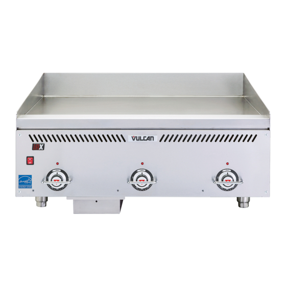
HEAVY DUTY GAS GRIDDLES
For additional information on Vulcan or to locate an authorized parts and
service provider in your area, visit our website at www.vulcanequipment.com
©ITW Food Equipment Group, LLC
3600 North Point Blvd.
Baltimore, MD 21222
VCCG36
MODELS
VCCG24
VCCG36
VCCG48
VCCG60
VCCG72
RETAIN THIS MANUAL FOR FUTURE USE
FORM F-45402 (rev. 10-15)
Advertisement
Table of Contents

Related Manuals for Vulcan-Hart VCCG24


Summary of Contents for Vulcan-Hart VCCG24
- Page 1 INSTALLATION & OPERATION MANUAL HEAVY DUTY GAS GRIDDLES MODELS VCCG24 VCCG36 VCCG48 VCCG60 VCCG72 VCCG36 For additional information on Vulcan or to locate an authorized parts and service provider in your area, visit our website at www.vulcanequipment.com RETAIN THIS MANUAL FOR FUTURE USE ©ITW Food Equipment Group, LLC...
- Page 2 IMPORTANT FOR YOUR SAFETY THIS MANUAL HAS BEEN PREPARED FOR PERSONNEL QUALIFIED TO INSTALL GAS EQUIPMENT, WHO SHOULD PERFORM THE INITIAL FIELD START-UP AND ADJUSTMENTS OF THE EQUIPMENT COVERED BY THIS MANUAL. POST IN A PROMINENT LOCATION THE INSTRUCTIONS TO BE FOLLOWED IN THE EVENT THE SMELL OF GAS IS DETECTED.
-
Page 3: Table Of Contents
TABLE OF CONTENTS GENERAL…………………………………………………………………………………………...…...… Specifications……………………………………………………………………….……………..INSTALLATION……………………………………………………………………………………………. Unpacking………………………………………………………………………………………………. Location…………………………………………………………………………………………………. Installation Codes and Standards……………………………………………………………………. Griddle Mounted On Stands with Casters…………………………………………………………… Flue Connections………………………………………………………………………………………. Stands…………………………………………………………………………………………………… Gas Connections……………………………………………………………………………………….. Testing The Gas Supply System………………..…………………………………………………… Gas Pressure Regulation…………..…………………………………………………………………. Electrical Connections ………………………………………………………………………………… OPERATION……………………………………………………………………………………………….. Before First Use………………………………………………………………………………………… Seasoning The Griddle…………..……………………………………………………………………. Controls …………………..…………………………………………………………………………….. -
Page 4: General
Thoroughly read this entire manual and carefully follow all of the instructions provided . BTU/hr Input BTU/hr Input Standard Infrared Burner Optional Number of Model Burners U-Shaped Burner Natural Gas Propane Gas VCCG24 48,000 44,000 60,000 VCCG36 72,000 66,000 90,000 VCCG48 96,000 88,000... -
Page 5: Installation Codes And Standards
Do not permit air to blow directly at the griddle. Avoid open windows next to the griddle wherever possible. Avoid wall-type fans which create air cross-currents within the room. This griddle is Design Certified for installation on a non -combustible counter with 4” legs, or combustible floor with a stand. -
Page 6: Flue Connections
If disconnection of the restraint is necessary, turn off the gas supply before disconnecting. Reconnect the restraint prior to turning the gas supply on and returning the griddle to its installation position. Casters are only supplied on a griddle stand. If the griddle is moved for any reason the griddle should be re-leveled (see LEVELING in this manual). -
Page 7: Gas Pressure Regulation
GAS PRESSURE REGULATION The VCCG griddle is constructed with internal gas regulators on each bur ner valve. The valves are pre set to 4” W.C. on natural gas units or 10” W.C. on propane gas units. An external gas regulator is not required as long as the gas pressure supplied to the unit is not greater than ½... -
Page 8: Seasoning The Griddle
SEASONING THE GRIDDLE Season the griddle to avoid possible surface corrosion before fir st use, and after every cleaning. This will also help reduce the sticking of cooked food product. Heat griddle to a low temperature (300-350°F) and apply a small amount of cooking oil – about one ounce per square foot of surface. -
Page 9: Startup Of Griddle
to ignite the pilot. Once the pilot is lit and recognized by the igniter safety, the light will illuminate a steady green color. The pilot must be ignited (burning) and the igniter cycle light must be emitting a steady green color before the griddle burner will be allowed to ignite. -
Page 10: Shutdown Of Griddle
SHUTDOWN OF GRIDDLE Push the power switch to the OFF position, all lights should go off indicating that the griddle is no longer heating. EXTENDED SHUTDOWN OF GRIDDLE 1. Push the power switch to the OFF position 1. Shut the main gas supply valve to the OFF position. 2. -
Page 11: Cleaning
ZONE 1 ZONE 2 ZONE 3 ZONE 4 (300°F) (350°F) (350°F) (400°F) PRODUCT PRODUCT PRODUCT S a us ag e S t e ak (R ar e ) P a nc ak es O m el e t E g gs (H a r d F ri e d ) S t i r F r y V e g et a bl e s F re nc h T o as t H as h B r o w n s... -
Page 12: Cleaning The Standard Steel Griddle Plate Cooking Surface
To keep the griddle clean and operating at peak efficiency, follow these procedures: AFTER EACH USE Clean the griddle cooking surface accordingly to the type of surfa ce on your model. See the specific cleaning instructions by cooking surface finish. Empty the grease drawer throughout the day as needed. -
Page 13: Cleaning The Optional Chrome Griddle Griddle Plate Cooking Surface
CLEANING THE OPTIONAL CHROME GRIDDLE PLATE COOKING SURFACE AFTER EACH USE Clean the griddle cooking surface regularly with a palmetto brush and a bladed griddle scraper during the work shift. Never use an abrasive scouring pad or griddle brick on a chrome plate surface. -
Page 14: Adjustments
ADJUSTMENTS CALIBRATION 1. Each thermostat controls a 12” zone of the griddle. Using a Surface Probe temperature measurement device, observe the temperatures at the center points of the cooking zones. These points are located by starting 6” f rom the side splash (left or right) and every 12”... -
Page 15: Leveling
LEVELING The griddle must be level (side-to-side and front-to-back) during operation to ensure proper performance. Improper leveling can result in uneven temperature distribution, cold spots, and possibly damage electrical components. 1. Place a level on the griddle. 2. Adjust legs by turning the bullet feet at the bottom of each leg. Using pliers or a crescent wrench, turn the feet counter -clockwise to increase height, and clockwise to decrease height until leveling is achieved. -
Page 16: Troubleshooting
TROUBLESHOOTING PROBLEM POSSIBLE CAUSES 1. Cooking surface temp is above set point . Heat does not come on 2. Pilot burner not lit. when individual 3. Problem with burner solenoid valves. (Call for service) thermostat knob is set 4. Problem with thermocouple. (Call for service) 5. -
Page 17: Accessory Installation
ACCESSORY INSTALLATION The griddle and its parts are hot. Use care when operating, cleaning or servicing the griddle. SIDE VIEW... - Page 18 SIDE VIEW FRONT VIEW...
- Page 19 NOTES...
Need help?
Do you have a question about the VCCG24 and is the answer not in the manual?
Questions and answers