Chapters
Table of Contents

Related Manuals for REXROTH IndraControl L40 Series


Summary of Contents for REXROTH IndraControl L40 Series
- Page 1 Electric Drives Linear Motion and and Controls Hydraulics Assembly Technologies Pneumatics Service Rexroth IndraControl L40 R911308429 Edition 03 Project Planning Manual Buy: www.ValinOnline.com | Phone: 844-385-3099 | Email: CustomerService@valin.com...
- Page 2 120-0401-B321-03/EN 02/07 Third Edition Copyright 2007 Bosch Rexroth AG © Copying this document, giving it to others and the use or communication of the contents thereof without express authority, are forbidden. Offenders are liable for the payment of damages. All rights are reserved in the event of the grant of a patent or the registration of a utility model or design (DIN 34-1).
-
Page 3: Table Of Contents
IndraControl L40 Contents Contents System Presentation Brief Description of the IndraControl L40 ..................1-1 View .............................. 1-1 Related Documentations ......................1-2 Important Directions for Use Appropriate Use..........................2-1 Introduction ..........................2-1 Areas of Use and Application ....................2-2 Inappropriate Use ......................... 2-2 Safety Instructions for Electric Drives and Controls Introduction ........................... - Page 4 Mechanical Installation of the IndraControl L40 ................8-1 Mounting the IndraControl L40 ....................8-1 Dismounting the IndraControl L40................... 8-3 Mechanical Installation of Rexroth Inline Modules ............... 8-5 Mounting the Inline Modules....................8-5 Dismounting the Inline Modules ....................8-6 Fuse Replacement ........................8-7 Electric Installation........................
- Page 5 Housing Dimensions of the Modules of the Low Signal Level............9-8 Electrical Voltage and Data Routing................... 9-11 Electric Circuits and Voltage Supply Within a Rexroth Inline Station ......... 9-12 Diagnostic and Status Indicators ....................9-13 Indicators on the IndraControl L40 ..................9-13 Indicators on the Supply Terminals ..................
- Page 6 Contents IndraControl L40 DOK-CONTRL-IC*L40*****-PR03-EN-P Buy: www.ValinOnline.com | Phone: 844-385-3099 | Email: CustomerService@valin.com...
-
Page 7: System Presentation
DeviceNet and master axis encoder interfaces. The locally available I/O units can be extended by the Rexroth Inline I/O system, just by simply mounting the components side by side. Application programs, inclusive runtime, are completely stored to an easily accessible standardized compact flash medium. -
Page 8: Related Documentations
Identification PLC Programming with Rexroth IndraLogic; DOK-CONTRL-IL**PRO*V02-AW..-EN-P Operating and Programming Guide Rexroth Inline PROFIBUS DP; Application Manual DOK-CONTRL-R-IL*PBSSYS-AW..-EN-P Rexroth Inline PROFIBUS DP Terminal and Module Supply; DOK-CONTRL-R-IL*PB*-BK-FK..-EN-P Functional Description Rexroth IndraWorks Engineering; DOK-IWORKS-ENGINEE*V..-AW..-EN-P Operating and Programming Guide Rexroth WinStudio; Overall View and Functional Description DOK-CONTRL-WIS*PC**V06-KB..-EN-P... -
Page 9: Important Directions For Use
The user alone carries all responsibility of the risks. Before using Rexroth products, make sure that all the pre-requisites for appropriate use of the products are satisfied: •... -
Page 10: Areas Of Use And Application
Important Directions for Use IndraControl L40 Areas of Use and Application The IndraControl L40 of Rexroth is in equal measure appropriate to logic and motion applications . Note: The IndraControl L40 may only be used with the accessories and parts specified in this document. If a component has not been specifically named, then it may not be either mounted or connected. -
Page 11: Safety Instructions For Electric Drives And Controls
If you do not have the user documentation for your equipment, contact your local Bosch Rexroth representative to send this documentation immediately to the person or persons responsible for the safe operation of this equipment. -
Page 12: Hazards By Improper Use
Safety Instructions for Electric Drives and Controls IndraControl L40 Hazards by Improper Use High voltage and high discharge current! Danger to life or severe bodily harm by electric shock! DANGER Dangerous movements! Danger to life, severe bodily harm or material damage by unintentional motor movements! DANGER High electrical voltage due to wrong... -
Page 13: General Information
IndraControl L40 Safety Instructions for Electric Drives and Controls General Information • Bosch Rexroth AG is not liable for damages resulting from failure to observe the warnings provided in this documentation. • Read the operating, maintenance and safety instructions in your language before starting up the machine. -
Page 14: Protection Against Contact With Electrical Parts
Safety Instructions for Electric Drives and Controls IndraControl L40 • Operation is only permitted if the national EMC regulations for the application are met. The instructions for installation in accordance with EMC requirements can be found in the documentation "EMC in Drive and Control Systems". -
Page 15: Protection Against Electric Shock By Protective Low Voltage (Pelv)
Protection Against Electric Shock by Protective Low Voltage (PELV) All connections and terminals with voltages between 0 and 50 Volts on Rexroth products are protective low voltages designed in accordance with international standards on electrical safety. High electrical voltage due to wrong... -
Page 16: Protection Against Dangerous Movements
Safety Instructions for Electric Drives and Controls IndraControl L40 Protection Against Dangerous Movements Dangerous movements can be caused by faulty control of the connected motors. Some common examples are: • improper or wrong wiring of cable connections • incorrect operation of the equipment components •... -
Page 17: Protection Against Magnetic And Electromagnetic Fields During Operation And Mounting
IndraControl L40 Safety Instructions for Electric Drives and Controls Secure vertical axes against falling or dropping after ⇒ switching off the motor power by, for example: - mechanically securing the vertical axes - adding an external braking/ arrester/ clamping mechanism - ensuring sufficient equilibration of the vertical axes The standard equipment motor brake or an external brake controlled directly by the drive controller are... -
Page 18: Protection Against Contact With Hot Parts
Safety Instructions for Electric Drives and Controls IndraControl L40 Protection Against Contact with Hot Parts Housing surfaces could be extremely hot! Danger of injury! Danger of burns! Do not touch housing surfaces near sources of heat! ⇒ Danger of burns! CAUTION ⇒... -
Page 19: 3.11 Battery Safety
IndraControl L40 Safety Instructions for Electric Drives and Controls 3.11 Battery Safety Batteries contain reactive chemicals in a solid housing. Inappropriate handling may result in injuries or material damage. Risk of injury by incorrect handling! Do not attempt to reactivate discharged batteries by ⇒... - Page 20 3-10 Safety Instructions for Electric Drives and Controls IndraControl L40 Notes DOK-CONTRL-IC*L40*****-PR03-EN-P Buy: www.ValinOnline.com | Phone: 844-385-3099 | Email: CustomerService@valin.com...
-
Page 21: Technical Data
CML40.1: At least 32 Mbytes DRAM and at least. 64 kbytes NvRAM CML40.2: At least 64 Mbytes DRAM and at least 128 kbytes NvRAM Interfaces: Plus • Interface to functional Bosch Rexroth PC104 modules • Interface to I/O modules Rexroth Inline interface •... -
Page 22: Ambient Conditions
Technical Data IndraControl L40 Note: The power consumption of the IndraControl L40 (without additional modules and without connected I/O) is typically 9 watts. Ambient Conditions In operation Storage/Transport Max. surrounding air temperature +5 ... +55 °C -25 °C to +70 °C If the load is higher or if the surrounding air temperature is >... -
Page 23: Used Standards
IndraControl L40 Technical Data Danger of destruction by overheating ⇒ Ensure a surrounding air temperature of less than 45 °C. If surrounding air temperatures range from 45 °C to ⇒ DANGER 55 °C, the optionally available blower has to be used. An integrated blower control with hysteresis activates the blower if a critical internal temperature is reached;... -
Page 24: Compatibility Test
• Use 60/75 °C copper wire only. Compatibility Test All Rexroth controls and drives are developed and tested according to the latest state-of-the-art. As it is impossible to follow the continuing development of all materials (e.g. lubricants in machine tools) which may interact with our controls and drives, it cannot be completely ruled out that any reactions with the materials used by Bosch Rexroth might occur. -
Page 25: Dimensions
IndraControl L40 Dimensions Dimensions Housing Dimensions The IndraControl L40 housing is 175.4 mm long, 120 mm high and 75.9 mm deep. Please refer to the following figures for detailed dimensions: Maße_Unten.FH9 Fig. 5-1: Bottom view 175,4 Maße_Front.FH9 Fig. 5-2: Front view DOK-CONTRL-IC*L40*****-PR03-EN-P Buy: www.ValinOnline.com | Phone: 844-385-3099 | Email: CustomerService@valin.com... -
Page 26: Fig. 5-3: Lateral View From The Left
Dimensions IndraControl L40 75,9 Maße_Seite.FH9 Fig. 5-3: Lateral view from the left (the cutout for the top-hat rail is arranged centrally) DOK-CONTRL-IC*L40*****-PR03-EN-P Buy: www.ValinOnline.com | Phone: 844-385-3099 | Email: CustomerService@valin.com... -
Page 27: Display And Operating Components
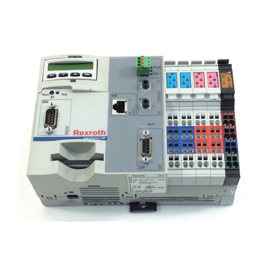
IndraControl L40 Display and Operating Components Display and Operating Components On its front, the IndraControl L40 is provided with the following display and operating components: a single-line display with four operating keys as well as a light-emitting diode and a reset button. Display and Operating Keys The display is a LCD display comprising 8 digits (5 x 10 dot matrix). -
Page 28: Reset Button And Light-Emitting Diode
Display and Operating Components IndraControl L40 Reset Button and Light-Emitting Diode The reset button and a red light-emitting diode are arranged in the section below the display. Reset.tif Fig. 6-2: Reset button and stop LED Reset Button The reset button can only be actuated with a tool, for instance with the tip of a pencil. -
Page 29: Connections And Interfaces
IndraControl L40 Connections and Interfaces Connections and Interfaces Overview of Connections on the Front Des. on the Type of connection Type of connector (integrated) Mating connector or cable (from housing outside) Serial RS232 interface D-Sub male connector, 9-pin D-Sub female connector, 9-pin Network connection: RJ45 female connector, 8-pin RJ45 male connector (8-core twisted... -
Page 30: Voltage Supply
Connections and Interfaces IndraControl L40 Voltage Supply External Supply Voltages The IndraControl L40 as well as any connected function modules and I/O PWR IN assemblies are supplied with power via the black terminal strip to the right of the IndraControl L40 unit. Slot 5: PWR.tif Fig. -
Page 31: Fig. 7-3: Pin Assignment Of The Voltage Module
IndraControl L40 Connections and Interfaces This voltage module (PWR IN) is used to feed the following three voltages: U (24 V supply voltage), U (24 V segment voltage) and U (24 V main voltage): Terminal Signal + 24 V DC segment voltage (U + 24 V DC supply voltage (U LGND (ground supply voltage) 1.4 and 2.4... -
Page 32: Fig. 7-8: Main Circuit
The maximum current carrying capacity is 8 A. If the limit has been Current Carrying Capacity reached, a new power terminal must be used. IndraControl L40 Rexroth Inline PWR IN SEG/F PWR IN GNDL Spannung_UM.FH9... -
Page 33: Fig. 7-9: Segment Circuit
The segment circuit supply U is to be connected to terminal 1.1 and is supplied through the following series Rexroth Inline I/O modules by the lateral contacts (voltage jumper). It forms the segment circuit or auxiliary circuit of the Rexroth Inline modules and the onboard I/Os. -
Page 34: Internally Generated Voltages
The +24 V analog voltage is generated from the voltage U . It starts in the IndraControl L40 and is supplied through all Rexroth Inline I/O modules by the lateral contacts (voltage jumper). The output signals of the analog modules are generated from the analog Function circuit in the analog terminals. -
Page 35: Digital Inputs And Outputs
IndraControl L40 Connections and Interfaces IndraControl L40 Rexroth Inline 24 PWR IN 24 SEG/F PWR IN GNDL Spannung_ULS.FH9 PWR IN Voltage module at the IndraControl L40 R-IL 24 PWR IN Power terminal R-IL 24 SEG/F Segment terminal with fuse For wiring instructions, please refer to the chapter on "Electric Installation"... -
Page 36: Digital Onboard Inputs
Connections and Interfaces IndraControl L40 Digital Onboard Inputs The left-hand section of the connector panel provides eight digital inputs as onboard inputs. Slots 1 and 2: Eingänge.tif Fig. 7-11: Digital inputs Note: Observe the color-coding of the connectors. Number of inputs Connection method 2-wire connection Electrical isolation from U... -
Page 37: Digital Outputs
IndraControl L40 Connections and Interfaces Criteria for connecting 2-wire proximity switches: Static current < 2.5 mA Voltage drop < 6 V Fig. 7-12: Data of digital inputs Light-emitting diodes indicating the current state of the inputs are arranged on the top of the input terminals. LEDs 1, 2, 3, 4 Meaning The assigned input is not set. -
Page 38: Fig. 7-16: Data Of Digital Outputs
7-10 Connections and Interfaces IndraControl L40 Number of outputs Connection method 2-wire connection • Semiconductor outputs, Output type non-saving • Protected, with automatic restart • Current-carrying Electrical isolation from U Electrical isolation from U Output voltage, nominal value 24 V Rated output current: Nominal value 0.5 A... -
Page 39: Fig. 7-17: Status Leds Of Digital Outputs
7-11 IndraControl L40 Connections and Interfaces Light-emitting diodes indicating the current status of the outputs are arranged above the output terminals. LEDs 1, 2, 3, 4 Meaning The assigned output is not set. Yellow The assigned output is set. Fig. 7-17: Status LEDs of digital outputs An additional two-color light-emitting diode (identified by D) emits green light in case the 24 V voltage is present and red light in case of a short- circuit or overload. -
Page 40: Interfaces
7-12 Connections and Interfaces IndraControl L40 Interfaces Serial RS232 Interface A serial RS232 interface is provided at X3C. Serial RS232 Interface D-Sub male connector, 9-pin Type: RS232 Cable length: Max. 15 m Cable type: Shielded, twisted Shield applied to the metal housing of the plug-in connector Com_sst.cdr Fig. -
Page 41: Ethernet Interface
• LED at the top (Link): Flashes green, if there is an Ethernet connection • LED at the bottom (Send): Flashes orange, if the data transmission occurs via this line Bosch Rexroth recommends the use of an STP cable of category 5. You will find cables for this interface on page 11-6. DOK-CONTRL-IC*L40*****-PR03-EN-P... -
Page 42: Profibus Dp (Optional)
7-14 Connections and Interfaces IndraControl L40 PROFIBUS DP (Optional) Optionally, the IndraControl L40 provides a PROFIBUS interface PROFIBUS DP Interface according to DIN EN 50170, Part 2. D-Sub female connector, 9-pin Type: RS485 Cable type: Shielded, twisted pair Transmission rate: 10 or 100 Mbits/s RxD/TxD-P CNTR-T... -
Page 43: Sercos (Optional)
7-15 IndraControl L40 Connections and Interfaces A "Send" light-emitting diode is arranged on the top of the PROFIBUS interface. "Send" LED LED on Output of data by the IndraControl L40 Fig. 7-23: "Send" light-emitting diode SERCOS (Optional) The optical SERCOS fibers must be connected to the optional connectors X7S1 and X7S2 SERCOS Interface X7S1 (receiver) and X7S2 (transmitter). -
Page 44: Interface For Compact Flash Card
IndraControl L40 is in operation. DANGER Inline Bus To its right, the IndraControl L40 can be extended by additional Rexroth Inline modules. Such modules permit an extension of the I/O unit to 32- byte inputs and 32-byte outputs. -
Page 45: Function Modules
IndraControl L40 in the corresponding chapter. Plus This 120-pin connector is a Bosch Rexroth PC104 connector where the PCI signals as well as additional system-specific signals are applied. In other words, only the function modules especially developed for the IndraControl L40 can be connected to this connector. -
Page 46: Fig. 7-28: Ambient Conditions
7-18 Connections and Interfaces IndraControl L40 Ambient Conditions Ambient conditions In operation Storage/ Transport Max. surrounding air +5 ... +55 °C -25 °C to +70 °C temperature RH-2; 5 % to 95 % accor- Relative humidity ding to DIN EN 61131-2, non-condensing. -
Page 47: Cfl01.1-Y1 Sram Function Module
7-19 IndraControl L40 Connections and Interfaces CFL01.1-Y1 SRAM Function Module CFL01.1-Y1.tif S1, switch for slot number Battery case Mounting rail interlock Fig. 7-29: SRAM function module The battery inserted in the module is automatically activated with the first commissioning and buffers then the data of the storage module for several years. -
Page 48: Fig. 7-30: Insert New Battery
7-20 Connections and Interfaces IndraControl L40 Open the battery case when the control is switched on and pull the battery Battery Exchange with the plastic strap out of the housing. Note: Data loss when control is switched off! Consider that the control is switched on during battery exchange. -
Page 49: Cfl01.1-V1 Devicenet Master Function Module
7-21 IndraControl L40 Connections and Interfaces CFL01.1-V1 DeviceNet Master Function Module CFL01.1-Y1.tif S1, switch for slot number Stat, status indicator of the function module MNS, module/network status X7D, DeviceNet connector Mounting rail interlock Fig. 7-31: DeviceNet master module DOK-CONTRL-IC*L40*****-PR03-EN-P Buy: www.ValinOnline.com | Phone: 844-385-3099 | Email: CustomerService@valin.com... - Page 50 Acyclically 3 times fast with 5 Hz Hardware error detected, the device has to be exchanged, flashing 8 times slow please contact Bosch Rexroth. 0,5 Hz to 1 Hz Green Cyclically Fast, 5 Hz No configuration error, device is online and ready for the field flashing bus communication;...
-
Page 51: Cfl01.1-P1 Profibus Dp Master Function Module
7-23 IndraControl L40 Connections and Interfaces CFL01.1-P1 Profibus DP Master Function Module CFL01.1-Y1.tif S1, switch for slot number Stat, status indicator of the function module Bus, DP status X7P, Profibus DP connector Mounting rail interlock Fig. 7-34: Profibus DP master function module Note: Cable fixing during installation required! DOK-CONTRL-IC*L40*****-PR03-EN-P... - Page 52 Acyclically 3 times fast with 5 Hz Hardware error detected, the device has to be exchanged, flashing 8 times slow please contact Bosch Rexroth. 0,5 Hz to 1 Hz Green Cyclically Fast, 5 Hz No configuration error, device is online and ready for the field flashing bus communication;...
-
Page 53: Cfl01.1-R3 Sercos Iii Function Module
Housing Shield Fig. 7-38: Pin assignment of the X7S1, X7S2 connector Bosch Rexroth recommends the use of an STP cable of category 5. You will find cables for this interface on page 11-7. Note: Cable fixing during installation required! For further descriptions please refer to the particular system- specific manual. -
Page 54: Cfl01.1-Q2 Cross Communication Function Module
7-26 Connections and Interfaces IndraControl L40 CFL01.1-Q2 Cross Communication Function Module CFL01.1-Q2.TIF S1, switch for slot number Ma, indicator of the cross communication MASTER mode Sl, indicator of the cross communication SLAVE mode Er-P, primary ring error Er-S, secondary ring error X7S1, FO transmitter of the primary ring (SERCOS transmitter) X7S2, FO receiver of the primary ring (SERCOS receiver) X7S3, FO transmitter of the secondary ring (SERCOS transmitter) -
Page 55: Cfl01.1-E2 Fast I/O Function Module
7-27 IndraControl L40 Connections and Interfaces CFL01.1-E2 Fast I/O Function Module CFL01.1-E2.TIF S1, switch for slot number Stat, status indicator of the function module X2I1, digital inputs X2D1, digital inputs/outputs X2O1, digital outputs X1S, power supply and FE Mounting rail interlock Fig. -
Page 56: Fig. 7-41: Input And Output Connectors X2I1, X2D2 And X2O1
7-28 Connections and Interfaces IndraControl L40 Interfaces Input connector Input/output connector Output connector X2I1 connection X2D1 connection X2O1 connection Input 0 Input/output 0 Output 0 Input 1 Input/output 1 Output 1 Input 2 Input/output 2 Output 2 Input 3 Input/output 3 Output 3 Input 4 Input/output 4... -
Page 57: Fig. 7-44: Wiring The Module
7-29 IndraControl L40 Connections and Interfaces Wiring the Module Modul_FastIO_Anschluesse.bmp Fig. 7-44: Wiring the module DOK-CONTRL-IC*L40*****-PR03-EN-P Buy: www.ValinOnline.com | Phone: 844-385-3099 | Email: CustomerService@valin.com... -
Page 58: Fig. 7-45: Data Of Digital Inputs
7-30 Connections and Interfaces IndraControl L40 Destruction of the module by improper connection! Avoid polarity reversal with simultaneous short-circuit ⇒ of the output lines WARNING ⇒ Avoid polarity reversal with simultaneous connection of externally polarized suppressor diodes Do not apply an external voltage greater than the ⇒... -
Page 59: Fig. 7-46: Data Of Digital Outputs
7-31 IndraControl L40 Connections and Interfaces Digital Outputs X2I1, X2D1 Number of outputs 16 (8 of the 16 can be selected bit by bit as input or output) Connection method 1-wire connection Output type Semiconductor outputs, non-saving Protected, with automatic restart Current-carrying Electrical isolation to the logic supply Output voltage, nominal value... -
Page 60: Fig. 7-47: Peripheral Voltage According To Din En 61131-2
7-32 Connections and Interfaces IndraControl L40 Connection of inductive load A line break, the unplugging of a connector for inductive load, e. g. magnetic valves, contactors etc. or the volitional interrupting by a mechanical contact causes very high interference levels. These levels can be spread by galvanic, inductive or capacitive coupling in the system and potentially lead to malfunctions of the installation or other installations. -
Page 61: Cfl01.1-N1 Cam Switch Function Module
7-33 IndraControl L40 Connections and Interfaces CFL01.1-N1 Cam Switch Function Module CFL01.1-Y1.tif S1, switch for slot number Stat, status display X2O1, digital outputs X2O1, digital outputs Status LED of the outputs X1S, load supply of the outputs Mounting rail interlock Fig. -
Page 62: Fig. 7-49: Output Connectors X2O1 And X2O2
7-34 Connections and Interfaces IndraControl L40 Interfaces Output connector X2O1 connection Output connector X2O2 connection Output 0 Output 0 Output 1 Output 1 Output 2 Output 2 Output 3 Output 3 Output 4 Output 4 Output 5 Output 5 Output 6 Output 6 Output 7 Output 7... -
Page 63: Fig. 7-52: Wiring The Module
7-35 IndraControl L40 Connections and Interfaces Wiring the Module Modul_Nockenschaltwerk_Anschluesse.jpg Fig. 7-52: Wiring the module Destruction of the module by improper connection! ⇒ Avoid polarity reversal with simultaneous short-circuit of the output lines WARNING Avoid polarity reversal with simultaneous connection ⇒... -
Page 64: Fig. 7-53: Data Of Digital Outputs
7-36 Connections and Interfaces IndraControl L40 Damages of the module! ⇒ If the maximum permissible current consumption of the function module is exceeded, components of the module can be destructed WARNING Removing and inserting the spring terminals under ⇒ voltage can damage the electrical contacts Digital Outputs Number of outputs Connection method... -
Page 65: Fig. 7-54: Peripheral Voltage According To Din En 61131-2
7-37 IndraControl L40 Connections and Interfaces Connection of inductive load A line break, the unplugging of a connector for inductive load, e. g. magnetic valves, contactors etc. or the volitional interrupting by a mechanical contact causes very high interference levels. These levels can be spread by galvanic, inductive or capacitive coupling in the system and potentially lead to malfunctions of the installation or other installations. - Page 66 7-38 Connections and Interfaces IndraControl L40 DOK-CONTRL-IC*L40*****-PR03-EN-P Buy: www.ValinOnline.com | Phone: 844-385-3099 | Email: CustomerService@valin.com...
-
Page 67: Installation And Maintenance
Top-Hat Rail and then exerting slight pressure to engage the control in the lower section of the housing. If necessary, mount Rexroth Inline modules in series with the control. For Mounting Rexroth Inline Modules in Series more detailed information, please refer to section "Mechanical Installation of Rexroth Inline Modules"... -
Page 68: Fig. 8-1: Module Slot And Slot Number Of Function Modules
Installation and Maintenance IndraControl L40 FM_Steckplatznummer.bmp Fig. 8-1: Module slot and slot number of function modules FM_Montage.bmp Fig. 8-2: Fitting and removing a function module The function modules are fitted on the left 120-pin female connector of Fitting a Function Module the IndraControl L40. -
Page 69: Dismounting The Indracontrol L40
Additionally, the clearance for mounting, dismounting, connectors and cable outlets has to be provided. Attaching the End Clamps / Attach the end clamps to either side of the Rexroth Inline station. These CLIPFIX Clamps end clamps ensure that the station is securely mounted to the top-hat rail and are also provided as lateral termination elements. -
Page 70: Fig. 8-3: Before Dismounting The Indracontrol L40, The First Rexroth Inline
Installation and Maintenance IndraControl L40 Demontage.FH9 Fig. 8-3: Before dismounting the IndraControl L40, the first Rexroth Inline module must be removed. Removing the IndraControl L40 You can now remove the IndraControl L40 from the top-hat rail by from the Top-Hat Rail... -
Page 71: Mechanical Installation Of Rexroth Inline Modules
Installation and Maintenance Mechanical Installation of Rexroth Inline Modules Rexroth Inline modules can be added in series to the right of the IndraControl L40 as appropriate. No tool is required. On connecting these modules in series, the potential and bus signal connection (voltage and data routing) between the individual components of the station is established automatically. -
Page 72: Dismounting The Inline Modules
Installation and Maintenance IndraControl L40 Modulaufrasten.FH9 Fig. 8-4: Latching on a module Dismounting the Inline Modules Proceed as follows to remove a module (Fig. 8-5): • Remove the labeling field, if present (A1 in Fig. A). Note: If any of the modules is provided with more connectors than one, all these connectors must be removed from the module. -
Page 73: Fuse Replacement
Removing a module Replacing a Module If you intend to replace a module within the Rexroth Inline station, proceed as described above to remove it. Do not latch on the adjacent connector of the neighboring module to the left yet. -
Page 74: Fig. 8-6: Fuse Replacement
Installation and Maintenance IndraControl L40 Proceed as follows to replace the fuse (also see the illustrations in Fig. 8-6): • Swing up the fuse lever (Fig. A). • Put a screwdriver behind a metal contact of the fuse (Fig. B). •... -
Page 75: Electric Installation
IndraControl L40 Installation and Maintenance Electric Installation The following rules for setting up a system, in which the electrical equipment like control systems are used, must be adhered to: • DIN VDE 0100 • DIN EN 60 204-1 • DIN EN 50 178 Danger of personal injury and material damage! ⇒... -
Page 76: 24 V Voltage Supply
8-10 Installation and Maintenance IndraControl L40 24 V Voltage Supply Setup without Electrical Isolation The most easiest connection method is the establishment of an electrical isolation between the internal logic and the peripheral supply. In this case, a power supply unit is appropriate to supply the IndraControl L40. -
Page 77: Fig. 8-8: Setup With Electrical Isolation
8-11 IndraControl L40 Installation and Maintenance Setup with Electrical Isolation According to DIN EN 60 204-1, electrical isolation should be provided between the logic of the central processing unit and the I/O interfaces of the peripheral assemblies. Accordingly, the voltage U (24 V logic voltage) is electrically isolated from the voltages U (24 V segment... -
Page 78: Fig. 8-9: Reference Conductor Connected To The Protective Conductor
8-12 Installation and Maintenance IndraControl L40 Reference Conductor Connected to the Protective Conductor If the reference conductor (N, 0 V) is connected to the protective conductor system, then this connection must be arranged at a central point (e. g. at the load power supply unit or at the isolating transformer). In addition, it must be possible to break this connection for measuring ground leakage currents. -
Page 79: Fig. 8-10: Reference Conductor Not Connected To The Protective Conductor
8-13 IndraControl L40 Installation and Maintenance Reference Conductor Not Connected to the Protective Conductor If the reference conductor (N, 0 V) is not connected to the protective conductor system, then an appropriate ground fault detector must be used to prevent inadvertent power-up in case of insulation faults. Hence, the supply current circuit is a SELV circuit. -
Page 80: Main Switch And Fuses
8-14 Installation and Maintenance IndraControl L40 Dimensioning the Voltage Supply When dimensioning the voltage supply, consider the maximum currents (see DIN VDE 0100-523). A voltage of 20.4 … 28.8 V must be applied directly to the unit. The voltage must be maintained even if •... -
Page 81: Ground Connection
Installation and Maintenance Ground Connection An optimum ground connection is required to keep possible interferences away from the IndraControl L40 and the Rexroth Inline modules and to discharge them to the ground. Functional Earth Ground The top-hat rail used for mounting the IndraControl L40 must be mounted to a grounded metal carrier, e. -
Page 82: Fig. 8-11: Overview: Shield Connection Of Analog Sensors And Actuators
8-16 Installation and Maintenance IndraControl L40 Shielding in Case of Analog Sensors and Actuators • Always connect analog sensors and actuators using shielded and twisted cable pairs. • Connect the shield system via the shield connector. Connection of the shield to the shield connector is described on page 8-19, "Connecting Shielded Lines Via the Shield Connector". - Page 83 8-17 IndraControl L40 Installation and Maintenance Connecting the Analog Output Module R-IB IL AO ... Note: • Connect the shield system via the shield connector (see page 8-19, "Connecting Shielded Lines Via the Shield Connector"). • Connect the shield system to the FE potential over an area as large as possible.
-
Page 84: Connecting Lines To Tension Spring Connection Points
Note: For additional information on the connection method, please refer to Manual \2\ Rexroth Inline PROFIBUS DP; Application Manual (see chapter entitled "Further Documentation" on page 1-2). DOK-CONTRL-IC*L40*****-PR03-EN-P Buy: www.ValinOnline.com | Phone: 844-385-3099 | Email: CustomerService@valin.com... -
Page 85: Fig. 8-15: Connecting The Shield To The Shield Connector
• Place the braid around the outer sheath (2). • Remove the protective foil. • Strip the lines for 8 mm (2). Note: The Rexroth Inline wiring is provided without connector sleeves. DOK-CONTRL-IC*L40*****-PR03-EN-P Buy: www.ValinOnline.com | Phone: 844-385-3099 | Email: CustomerService@valin.com... -
Page 86: Maintenance
8-20 Installation and Maintenance IndraControl L40 • Put a screwdriver into the actuation slot of the appropriate terminal Wiring the Connectors point (Fig. 8-14, A) as far as necessary to be able to insert the core into the opening of the spring. •... -
Page 87: Structure Of The Rexroth Inline Terminals
ZBFM: Zack marker strips, flat (also see the chapter entitled "Identification of Function and Labeling" on page 9-5). Electronic Socket All electronic parts of the Rexroth Inline module as well as the voltage and data jumpers are accommodated in the electronic socket. Overall Widths... -
Page 88: Connectors
Structure of the Rexroth Inline Terminals IndraControl L40 Connectors The connection of the peripheral equipment or the supply voltages is provided in the form of a connector, that can be disconnected from the electronic socket. This pluggable connection has the following advantages: Advantages •... -
Page 89: Fig. 9-3: Color-Coding Of The Terminal Points
IndraControl L40 Structure of the Rexroth Inline Terminals Extended double-signal connector This gray connector is used for connecting four signals as 3- wire connection (e. g. digital input/output signals). Color Signal at the terminal point Blue Green / yellow Functional earth ground Fig. -
Page 90: Fig. 9-5: Connector Coding
Structure of the Rexroth Inline Terminals IndraControl L40 Note: To avoid malfunctions, only latch the connector onto the terminal it is intended for. Refer to the specific data sheet of each module to select the appropriate connector. The black connector may not be latched onto a module that is intended for a double-signal connector. -
Page 91: Identification Of Function And Labeling
IndraControl L40 Structure of the Rexroth Inline Terminals Identification of Function and Labeling For visual identification of their function, the modules are color-coded (1 in Fig. 9-6). Funktionskennzeichnung.FH9 Fig. 9-6: Identification of function The various functions are identified by the following colors:... -
Page 92: Fig. 9-8: Numbering Of Terminal Points
Structure of the Rexroth Inline Terminals IndraControl L40 Numbering of the terminal points is illustrated by means of an 8-slot Labeling/Numbering of Terminal Points module. Klemmpunktnumm.FH9 Fig. 9-8: Numbering of terminal points The slots (connectors) on a socket are numbered consecutively (1 in Slot/Connector Fig. -
Page 93: Fig. 9-9: Labeling Of Modules
IndraControl L40 Structure of the Rexroth Inline Terminals In addition to the above labeling of the modules, you can label the slots, Additional Labeling terminal points and connections with zack marker strips (ZBFMs) and labeling fields. Modulbeschr.FH9 Fig. 9-9: Labeling of modules There are various possibilities for labeling slots and terminal points: You can label each connector individually with zack marker strips. -
Page 94: Housing Dimensions Of The Modules Of The Low Signal Level
Level Today, small I/O stations are often used in 80 mm standard control boxes. The Rexroth Inline modules have been designed for use in this type of control box. The housing dimensions of a module are defined by the dimensions of the electronic socket and the connector. - Page 95 IndraControl L40 Structure of the Rexroth Inline Terminals 4-Slot Housing 71,5 mm (2.815") 24,4 mm (0.961") Sockelmaß4.FH9 Fig. 9-11: Dimensions of the electronic sockets (4-slot housing) 8-Slot Housing 71,5 mm (2.815") 48,8 mm (1.921") Sockelmaß8.FH9 Fig. 9-12: Dimensions of the electronic sockets (8-slot housing) DOK-CONTRL-IC*L40*****-PR03-EN-P Buy: www.ValinOnline.com | Phone: 844-385-3099 | Email: CustomerService@valin.com...
-
Page 96: Fig. 9-13: Connector Dimensions
9-10 Structure of the Rexroth Inline Terminals IndraControl L40 Connectors 12,2 mm (0.480") 12,2 mm 12,2 mm (0.480") (0.480") Steckermaß.FH9 Standard connector Shield connector Extended double-signal connector Fig. 9-13: Connector dimensions The connector depth is irrelevant as it has no effect on the overall module depth. -
Page 97: Electrical Voltage And Data Routing
Structure of the Rexroth Inline Terminals Electrical Voltage and Data Routing An essential feature of the Rexroth Inline product family is the internal voltage routing system. The electrical connection between the individual station devices is established automatically when the station is set up. -
Page 98: Electric Circuits And Voltage Supply Within A Rexroth Inline Station
Electric Circuits and Voltage Supply Within a Rexroth Inline Station There are several electric circuits within a Rexroth Inline station. These circuits are set up automatically, when the modules are latched to each other. The voltages of the different electric circuits are supplied to the connected modules via the voltage jumpers. -
Page 99: Diagnostic And Status Indicators
9-13 IndraControl L40 Structure of the Rexroth Inline Terminals Diagnostic and Status Indicators For quick failure diagnostics on site, the IndraControl L40 and all modules are equipped with diagnostic and status LEDs. The diagnostic indicators (red/green) provide information on the failure Diagnostics type and location. - Page 100 9-14 Structure of the Rexroth Inline Terminals IndraControl L40 "Ready" LED (optional) Meaning Watchdog not started yet Ready contact opened via the software (but the watchdog is still triggered internally). Green Ready contact closed; watchdogs still triggered. Ready error; at least one watchdog has responded.
-
Page 101: Indicators On The Supply Terminals
9-15 IndraControl L40 Structure of the Rexroth Inline Terminals Indicators on the Supply Terminals Klemmenanzeige.FH9 Fig. 9-26: Possible indicators on supply terminals (here: segment terminal without and with fuse) The following states are indicated by the supply terminals: Diagnostics Color... -
Page 102: Indicators On The Input/Output Modules
9-16 Structure of the Rexroth Inline Terminals IndraControl L40 Indicators on the Input/Output Modules Modulanzeige.FH9 Fig. 9-27: Indicators on the input/output modules The following states are indicated by the input/output modules: Diagnostics Color Status Description of LED states Green Local bus active... -
Page 103: Disposal And Environmental Protection
Furthermore, the products returned for disposal must not contain any undue foreign matter or foreign component. Please send the products free domicile to the following address: Bosch Rexroth AG Electric Drives and Controls Bürgermeister-Dr.-Nebel-Straße 2 D-97816 Lohr am Main Packaging Materials The packaging materials consist of cardboard, wood and polystyrene. -
Page 104: Recycling
10-2 Disposal and Environmental Protection IndraControl L40 Recycling Due to their high content of metal most of the product components can be recycled. In order to recycle the metal in the best possible way, the products must be disassembled into individual modules. Metals contained in electric and electronic modules can also be recycled by means of special separation processes. -
Page 105: Ordering Information
11-1 IndraControl L40 Ordering Information Ordering Information 11.1 Type Code The IndraControl L40 is available in various versions according to the following type codes. CML40.1 Abbrev. Column 1 2 3 4 6 7 8 9 1 2 3 4 6 7 8 9 1 2 3 4 6 7 8 9 1 2 3 4... -
Page 106: Fig. 11-2: Type Code Of The Indracontrol L40.2
11-2 Ordering Information IndraControl L40 CML40.2 Abbrev. Column 1 2 3 4 6 7 8 9 1 2 3 4 6 7 8 9 1 2 3 4 6 7 8 9 1 2 3 4 6 7 8 9 Example: C M L 4 0 . -
Page 107: Fig. 11-3: Type Code Of The Function Modules
11-3 IndraControl L40 Ordering Information Function Modules Abbrev. Column 1 2 3 4 6 7 8 9 1 2 3 4 6 7 8 9 1 2 3 4 6 7 8 9 1 2 3 4 6 7 8 9 Example: C F L 0 1 . -
Page 108: 11.2 Accessories
Connector set for IndraControl L40 Additional Accessories (Blower, Function Modules, Inline Modules and Interface Cables) Blower Ordering designation Part number Description CAL01.1-F1 R911306144 Blower Rexroth Function Modules Ordering designation Part number Description CFL01.1-Y1 R911170007 SRAM CFL01.1-V1 R911170001 DeviceNet master CFL01.1-P1... - Page 109 11-5 IndraControl L40 Ordering Information Digital output terminals: R-IB IL 24/230 DOR1/W R911289301 1 relay change-over contact, 5-253 V AC, 3 A, gold plated, to switch lamp loads, width: 12.2 mm R-IB IL 24 DO 2-2A R911289294 2 outputs, 24 V DC, 2 A, 4-wire connection, width: 12.2 mm R-IB IL 24 DO 4 R911289295...
- Page 110 11-6 Ordering Information IndraControl L40 Interface Cable Ordering designation Part number Description Serial interface: RKB0009/005,0 R911170155 RS232 cable, 9-pin DSUB on both sides, 5 m Ethernet interface: RKB0007/00,15 R911170146 Ethernet cable, 10-Base-T, CAT.5, crosslink, ready-made, with RJ45 connector on both sides, 0.15 m RKB0007/002,5 R911170147 Ethernet cable, 10-Base-T, CAT.5, crosslink, ready-made,...
- Page 111 11-7 IndraControl L40 Ordering Information SERCOS lines (FO): RKO0100/00,15 ROS0001- R911308249 FO cable, diameter: 2.2 mm, length: 0.15 m INK0414-ROS0001) RKO0100/00,25 (ROS0001- R911308248 FO cable, diameter: 2.2 mm, length: 0.25 m INK0414-ROS0001) RKO0100/00,30 (ROS0001- R911308247 FO cable, diameter: 2.2 mm, length: 0.3 m INK0414-ROS0001) RKO0100/00,50 (ROS0001- R911308246...
- Page 112 11-8 Ordering Information IndraControl L40 Notes DOK-CONTRL-IC*L40*****-PR03-EN-P Buy: www.ValinOnline.com | Phone: 844-385-3099 | Email: CustomerService@valin.com...
-
Page 113: List Of Figures
12-1 IndraControl L40 List of Figures List of Figures Fig. 1-1: Front view of an IndraControl L40 1-1 Fig. 1-2: Related documentations 1-2 Fig. 3-1: Hazard classification (according to ANSI Z535) 3-1 Fig. 4-1: Equipment 4-1 Fig. 4-2: Current consumption 4-1 Fig. - Page 114 Fig. 8-1: Module slot and slot number of function modules 8-2 Fig. 8-2: Fitting and removing a function module 8-2 Fig. 8-3: Before dismounting the IndraControl L40, the first Rexroth Inline module must be removed. 8-4 Fig. 8-4: Latching on a module 8-6 Fig.
- Page 115 Fig. 8-15: Connecting the shield to the shield connector 8-19 Fig. 8-16: Orientation of the shield clip 8-20 Fig. 9-1: Basic structure of a Rexroth Inline modules 9-1 Fig. 9-2: Rexroth Inline connector types 9-2 Fig. 9-3: Color-coding of the terminal points 9-3 Fig.
- Page 116 12-4 List of Figures IndraControl L40 DOK-CONTRL-IC*L40*****-PR03-EN-P Buy: www.ValinOnline.com | Phone: 844-385-3099 | Email: CustomerService@valin.com...
-
Page 117: Index
13-1 IndraControl L40 Index Index 2-slot housing 9-8 4-slot housing 9-9 8-slot housing 9-9 Accessories 11-4 Actuators 8-17 Addresses Digital inputs and outputs 7-7 Air pressure 4-2, 7-18 Ambient conditions 4-2 Analog input module IB IL 24 AI 2/SF 8-16 Analog output module IB IL AO ... - Page 118 13-2 Index IndraControl L40 Electric installation 8-9 Electrical isolation 8-11 Electronic socket 9-1 Dimensions of 2-slot housing 9-8 Dimensions of 4-slot housing 9-9 Dimensions of 8-slot housing 9-9 Overall widths 9-1 End plate 8-1 Environmental Protection 10-1 Ethernet connection 7-13 FE spring 9-12 FE voltage jumper 8-15 Function modules 7-17...
- Page 119 13-3 IndraControl L40 Index Latching on a module 8-6 Mounting 8-5 Mounting rail 8-1 Numbering of terminal points 9-6 Removing a module 8-7 Replacing a module 8-7 Shield connector 9-2, 9-10 Slot 9-6 Standard connector 9-2, 9-10 Status indicators 9-13 Structure 9-1 Supply voltages 9-12 Terminal point 9-6...
- Page 120 13-4 Index IndraControl L40 Operating components 6-1 Operating Keys 6-1 Ordering information 11-1 Output module IB IL AO... 8-17 Peripheral circuit 9-12 Potential equalization 8-15 Potential transmission 9-11 Power consumption 4-2 Power supply unit 8-9 PROFIBUS DP connection 7-14 PROFIBUS line Shielding 8-15 Ready contact 7-15 Recycling 10-2...
- Page 121 13-5 IndraControl L40 Index Zack marker strip 9-7 Zack marker strips 9-1 DOK-CONTRL-IC*L40*****-PR03-EN-P Buy: www.ValinOnline.com | Phone: 844-385-3099 | Email: CustomerService@valin.com...
- Page 122 13-6 Index IndraControl L40 DOK-CONTRL-IC*L40*****-PR03-EN-P Buy: www.ValinOnline.com | Phone: 844-385-3099 | Email: CustomerService@valin.com...
-
Page 123: Service & Support
14-1 IndraControl L40 Service & Support Service & Support 14.1 Helpdesk Unser Kundendienst-Helpdesk im Hauptwerk Lohr Our service helpdesk at our headquarters in Lohr am am Main steht Ihnen mit Rat und Tat zur Seite. Main, Germany can assist you in all kinds of inquiries. Sie erreichen uns Contact us +49 (0) 9352 40 50 60... -
Page 124: Kundenbetreuungsstellen
Tel.: +49 (0)171 333 88 26 service.svc@boschrexroth.de Vertriebsgebiet Süd Vertriebsgebiet West Gebiet Südwest Germany South Germany West Germany South-West Bosch Rexroth AG Bosch Rexroth AG Bosch Rexroth AG Landshuter Allee 8-10 Regionalzentrum West Service-Regionalzentrum Süd-West 80637 München Borsigstrasse 15 Siemensstr. 1... - Page 125 Netherlands – Niederlande/Holland Netherlands - Niederlande/Holland Norway - Norwegen Tightening & Press-fit: Bosch Rexroth B.V. Bosch Rexroth Services B.V. Bosch Rexroth AS TEMA S.p.A. Automazione Kruisbroeksestraat 1 Technical Services Electric Drives & Controls Via Juker, 28 (P.O. Box 32) Kruisbroeksestraat 1...
- Page 126 - Südafrika South Africa - Südafrika AIMS - Australian Industrial TECTRA Automation (Pty) Ltd. Tightening & Press-fit: Bosch Rexroth Pty. Ltd. Machinery Services Pty. Ltd. 100 Newton Road, Meadowdale Jendamark Automation No. 7, Endeavour Way 28 Westside Drive Edenvale 1609...
- Page 127 Asien - Asia (incl. Pacific Rim) China China China China Shanghai Bosch Rexroth Shanghai Bosch Rexroth Bosch Rexroth (China) Ltd. Bosch Rexroth (China) Ltd. Hydraulics & Automation Ltd. Hydraulics & Automation Ltd. Satellite Service Office Changchun Satellite Service Office Wuhan BRC Service Department 4/f, Marine Tower Rm.
- Page 128 Canada West - Kanada West CANADA SERVICE HOTLINE Mexico Mexico Bosch Rexroth Canada Corporation Bosch Rexroth Mexico S.A. de C.V. Bosch Rexroth S.A. de C.V. 5345 Goring St. Calle Neptuno 72 Calle Argentina No 3913 Burnaby, British Columbia Unidad Ind. Vallejo Fracc.
- Page 129 Buy: www.ValinOnline.com | Phone: 844-385-3099 | Email: CustomerService@valin.com...
- Page 130 Bosch Rexroth AG Electric Drives and Controls P.O. Box 13 57 97803 Lohr, Germany Bgm.-Dr.-Nebel-Str. 2 97816 Lohr, Germany Phone +49 (0)93 52-40-50 60 +49 (0)93 52-40-49 41 service.svc@boschrexroth.de www.boschrexroth.com Printed in Germany R911308429 DOK-CONTRL-IC*L40*****-PR03-EN-P Buy: www.ValinOnline.com | Phone: 844-385-3099 | Email: CustomerService@valin.com...
Need help?
Do you have a question about the IndraControl L40 Series and is the answer not in the manual?
Questions and answers