Sign In
Upload
Manuals
Brands
REXROTH Manuals
Control Unit
IndraControl L40 Series
REXROTH IndraControl L40 Series Manuals
Manuals and User Guides for REXROTH IndraControl L40 Series. We have
1
REXROTH IndraControl L40 Series manual available for free PDF download: Project Planning Manual
REXROTH IndraControl L40 Series Project Planning Manual (130 pages)
Brand:
REXROTH
| Category:
Control Unit
| Size: 4 MB
Table of Contents
Table of Contents
3
System Presentation
7
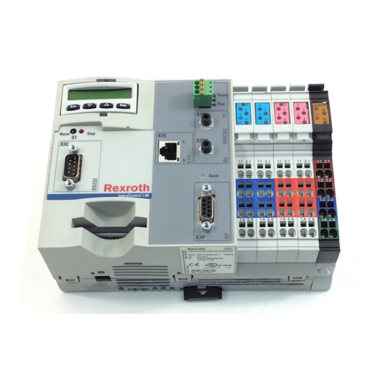
Brief Description of the Indracontrol L40
7
View
7
Fig. 1-1: Front View of an Indracontrol L40
7
Related Documentations
8
Fig. 1-2: Related Documentations
8
Important Directions for Use
9
Appropriate Use
9
Introduction
9
Areas of Use and Application
10
Inappropriate Use
10
Safety Instructions for Electric Drives and Controls
11
Introduction
11
Explanations
11
Fig. 3-1: Hazard Classification (According to ANSI Z535)
11
Hazards by Improper Use
12
General Information
13
Protection against Contact with Electrical Parts
14
Protection against Electric Shock by Protective Low Voltage (PELV)
15
Protection against Dangerous Movements
16
Protection against Magnetic and Electromagnetic Fields During Operation and Mounting
17
Protection against Contact with Hot Parts
18
3.10 Protection During Handling and Mounting
18
3.11 Battery Safety
19
3.12 Protection against Pressurized Systems
19
Technical Data
21
Equipment
21
Power Supply
21
Fig. 4-1: Equipment
21
Fig. 4-2: Current Consumption
21
Ambient Conditions
22
Fig. 4-3: Ambient Conditions
22
Used Standards
23
Fig. 4-4: Used Standards
23
Compatibility Test
24
Dimensions
25
Housing Dimensions
25
Fig. 5-1: Bottom View
25
Fig. 5-2: Front View
25
Fig. 5-3: Lateral View from the Left
26
Display and Operating Components
27
Display and Operating Keys
27
Fig. 6-1: Display with Four Operating Keys
27
Reset Button and Light-Emitting Diode
28
Fig. 6-2: Reset Button and Stop LED
28
Connections and Interfaces
29
Overview of Connections on the Front
29
Fig. 7-1: Indracontrol L40 Connections
29
Voltage Supply
30
External Supply Voltages
30
Fig. 7-2: Supply Voltage Connections
30
Fig. 7-3: Pin Assignment of the Voltage Module
31
Fig. 7-4: Diagnostic LED of the Power Terminal
31
Fig. 7-5: Diagnostic LED of the Segment Terminal
31
Fig. 7-6: Diagnostic LED of the Supply Voltage
31
Fig. 7-7: "FS" and "FN" Leds
31
Fig. 7-8: Main Circuit
32
Fig. 7-9: Segment Circuit
33
Internally Generated Voltages
34
Digital Inputs and Outputs
35
Address Assignment of Inputs and Outputs
35
Fig. 7-10: Address Assignment of Inputs and Outputs
35
Digital Onboard Inputs
36
Fig. 7-11: Digital Inputs
36
Digital Outputs
37
Fig. 7-12: Data of Digital Inputs
37
Fig. 7-13: Status Leds of Digital Inputs
37
Fig. 7-14: Light-Emitting Diode D
37
Fig. 7-15: Digital Outputs
37
Fig. 7-16: Data of Digital Outputs
38
Fig. 7-17: Status Leds of Digital Outputs
39
Fig. 7-18: Light-Emitting Diode D
39
Interfaces
40
Serial RS232 Interface
40
Fig. 7-19: RS232 Interface
40
Ethernet Interface
41
Fig. 7-20: Ethernet Interface
41
PROFIBUS DP (Optional)
42
Fig. 7-21: Parameters for PROFIBUS DP Line
42
Fig. 7-22: Maximum Segment Length in Relation to the Transmission Rate
42
SERCOS (Optional)
43
Ready Contact (Optional)
43
Fig. 7-23: "Send" Light-Emitting Diode
43
Fig. 7-24: Distortion Indicator
43
Fig. 7-25: Characteristic Data of the Ready Contact
43
Interface for Compact Flash Card
44
Inline Bus
44
Fig. 7-26: Ready LED
44
Function Modules
45
Overview
45
Technical Data
45
Fig. 7-27: Current and Power Supply
45
Fig. 7-28: Ambient Conditions
46
CFL01.1-Y1 SRAM Function Module
47
Fig. 7-29: SRAM Function Module
47
Fig. 7-30: Insert New Battery
48
CFL01.1-V1 Devicenet Master Function Module
49
CFL01.1-P1 Profibus DP Master Function Module
51
CFL01.1-R3 SERCOS III Function Module
53
Fig. 7-37: SERCOS III Module
53
Fig. 7-38: Pin Assignment of the X7S1, X7S2 Connector
53
CFL01.1-Q2 Cross Communication Function Module
54
CFL01.1-E2 Fast I/O Function Module
55
Fig. 7-40: Fast I/O Function Module
55
Fig. 7-41: Input and Output Connectors X2I1, X2D2 and X2O1
56
Fig. 7-42: Feeder Connector X1S
56
Fig. 7-43: States of the Status LED
56
Fig. 7-44: Wiring the Module
57
Fig. 7-45: Data of Digital Inputs
58
Fig. 7-46: Data of Digital Outputs
59
Fig. 7-47: Peripheral Voltage According to DIN en 61131-2
60
CFL01.1-N1 Cam Switch Function Module
61
Fig. 7-48: Cam Switch Function Module
61
Fig. 7-49: Output Connectors X2O1 and X2O2
62
Fig. 7-50: Feeder Connector X1S
62
Fig. 7-51: States of the Status LED
62
Fig. 7-52: Wiring the Module
63
Fig. 7-53: Data of Digital Outputs
64
Fig. 7-54: Peripheral Voltage According to DIN en 61131-2
65
Installation and Maintenance
67
Mechanical Installation of the Indracontrol L40
67
Mounting the Indracontrol L40
67
Fig. 8-1: Module Slot and Slot Number of Function Modules
68
Fig. 8-2: Fitting and Removing a Function Module
68
Dismounting the Indracontrol L40
69
Fig. 8-3: before Dismounting the Indracontrol L40, the First Rexroth Inline
70
Mechanical Installation of Rexroth Inline Modules
71
Mounting the Inline Modules
71
Dismounting the Inline Modules
72
Fig. 8-4: Latching on a Module
72
Fuse Replacement
73
Fig. 8-5: Removing a Module
73
Fig. 8-6: Fuse Replacement
74
Electric Installation
75
External Power Supply Unit
75
24 V Voltage Supply
76
Fig. 8-7: Setup Without Electrical Isolation
76
Fig. 8-8: Setup with Electrical Isolation
77
Fig. 8-9: Reference Conductor Connected to the Protective Conductor
78
Fig. 8-10: Reference Conductor Not Connected to the Protective Conductor
79
Main Switch and Fuses
80
Ground Connection
81
Shielding
81
Fig. 8-11: Overview: Shield Connection of Analog Sensors and Actuators
82
Connecting Lines to Tension Spring Connection Points
84
Fig. 8-14: Connecting Lines to the Tension Spring Connectors
84
Fig. 8-15: Connecting the Shield to the Shield Connector
85
Maintenance
86
Fig. 8-16: Orientation of the Shield Clip
86
Structure of the Rexroth Inline Terminals
87
Basic Structure of Terminals of the Low Signal Level
87
Electronic Socket
87
Fig. 9-1: Basic Structure of a Rexroth Inline Modules
87
Fig. 9-6: Identification of Function
87
Connectors
88
Fig. 9-2: Rexroth Inline Connector Types
88
Fig. 9-3: Color-Coding of the Terminal Points
89
Fig. 9-4: Connector Design
89
Fig. 9-5: Connector Coding
90
Identification of Function and Labeling
91
Fig. 9-7: Color Coding of the Modules
91
Fig. 9-8: Numbering of Terminal Points
92
Fig. 9-9: Labeling of Modules
93
Housing Dimensions of the Modules of the Low Signal Level
94
Fig. 9-10: Dimensions of the Electronic Sockets (2-Slot Housing)
94
Fig. 9-13: Connector Dimensions
96
Electrical Voltage and Data Routing
97
Fig. 9-14: Voltage and Data Routing
97
Fig. 9-15: Voltage Jumpers (See Fig. 9-14)
97
Electric Circuits and Voltage Supply Within a Rexroth Inline Station
98
Fig. 9-16: Data Jumpers (See Fig. 9-14 )
98
Diagnostic and Status Indicators
99
Indicators on the Indracontrol L40
99
Fig. 9-17: Meaning of the "STOP" LED
99
Indicators on the Supply Terminals
101
Indicators on the Input/Output Modules
102
Indicators on Other Inline Modules
102
Disposal and Environmental Protection
103
10.1 Disposal
103
Products
103
Packaging Materials
103
10.2 Environmental Protection
103
No Release of Hazardous Substances
103
Materials Contained in the Products
103
Recycling
104
Ordering Information
105
11.1 Type Code
105
Fig. 11-1: Type Code of the Indracontrol L40.1
105
Fig. 11-2: Type Code of the Indracontrol L40.2
106
Fig. 11-3: Type Code of the Function Modules
107
11.2 Accessories
108
Necessary Accessories (Connector Set)
108
Additional Accessories (Blower, Function Modules, Inline Modules and Interface Cables)
108
12 List of Figures
113
Index
117
Service & Support
123
14.1 Helpdesk
123
14.2 Service-Hotline
123
14.3 Internet
123
Vor der Kontaktaufnahme
123
Kundenbetreuungsstellen
124
Sales & Service Facilities
124
Advertisement
Advertisement
Related Products
REXROTH IndraControl L25
REXROTH IndraControl L45
REXROTH IndraControl L65
REXROTH IndraControl L75
REXROTH IndraControl L85
REXROTH IndraControl L25 CML...3N Series
REXROTH IndraControl L25 Series
REXROTH IndraControl L25 CML...PN Series
REXROTH CC-CS351
REXROTH CKR 12-90
REXROTH Categories
Engine
Controller
Control Unit
DC Drives
Media Converter
More REXROTH Manuals
Login
Sign In
OR
Sign in with Facebook
Sign in with Google
Upload manual
Upload from disk
Upload from URL