Chapters
Table of Contents

Related Manuals for REXROTH MTS-P01.2/G2


Summary of Contents for REXROTH MTS-P01.2/G2
- Page 1 Industrial Electric Drives Linear Motion and Service Mobile Hydraulics and Controls Assembly Technologies Pneumatics Automation Hydraulics Rexroth PLC Modules 294690 MTS-P01.2/G2 and Ausgabe 02 MTS-P02.2/G2 Project Planning Manual...
- Page 2 About this Documentation PLC Modules MTS-P01.2/G2 and MTS-P02.2/G2 Rexroth PLC Modules Title MTS-P01.2/G2 and MTS-P02.2/G2 Project Planning Manual Type of Documentation DOK-CONTRL-MTS-P0*.2G2-PR02-EN-P Document Typecode Document Number, 120-0400-B387-02/EN Internal File Reference This documentation describes how to configure, mount and commision Purpose of Documentation the MTS-P01.2/G2 and MTS-P02.2/G2.
-
Page 3: Table Of Contents
PLC Modules MTS-P01.2/G2 and MTS-P02.2/G2 Contents Contents Rexroth PLC MTS-P01.2 and MTS-P02.2 Brief Description..........................1-1 Side and Front View of the MTS-P01.2 and MTS-P02.2 .............. 1-2 Important Directions for Use Appropriate Use ..........................2-1 Introduction ..........................2-1 Areas of Use and Application....................2-2 Inappropriate Use.......................... - Page 4 Contents PLC Modules MTS-P01.2/G2 and MTS-P02.2/G2 BT Bus (X15)..........................5-2 Addressing ..........................5-4 Startup Mounting ............................6-1 Setting of Addresses ........................6-1 General Notes .......................... 6-1 Battery............................6-2 Status Information and Error Diagnosis ..................6-3 Indication of Operating States....................6-3 Indication of Errors........................
- Page 5 PLC Modules MTS-P01.2/G2 and MTS-P02.2/G2 Contents 12 Configurations 12-1 12.1 MTS-P0*.2-D2-B1-NN-NN-NN-FW ..................... 12-1 12.2 MTS-P0*.2-D2-B1-S4-NN-NN-FW ....................12-2 12.3 MTS-P0*.2-D2-P1-NN-NN-NN-FW ..................... 12-3 12.4 MTS-P0*.2-D2-B1-P1-S4-NN-FW....................12-4 13 Accessories 13-1 13.1 Selection List of Connectors and Ready-Made Cables .............. 13-1 14 List of Figures 14-1 15 Service &...
- Page 6 Contents PLC Modules MTS-P01.2/G2 and MTS-P02.2/G2 DOK-CONTRL-MTS-P0*.2G2-PR02-EN-P...
-
Page 7: Rexroth Plc Mts-P01.2 And Mts-P02.2
COM user interface (RS232), which is operated via the PLC user program, is provided for connection of a printer, a read-write memory, or an operating and visualization device, e.g. Rexroth BTV04/05. Multimode operation of the interface (RS232/RS422/RS485) is configured using an PLC function block. -
Page 8: Side And Front View Of The Mts-P01.2 And Mts-P02.2
Rexroth PLC MTS-P01.2 and MTS-P02.2 PLC Modules MTS-P01.2/G2 and MTS-P02.2/G2 Side and Front View of the MTS-P01.2 and MTS-P02.2 PLC inputs for Connector for PLC function the machine keys of the BTV20 function keys of (Local I/Os) Addressing of the BTV20/30 MTS-P01.2... -
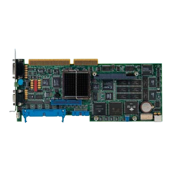
Page 9: Fig. 1-3: Front View Of Mts-P01.2/G2 And Mts-P02.2/G2
X5 Watchdog: PLC Ready X16 COM interface DEVICE: 0 SERNR: 0 PLC- READY Addressing used Contact load: for programming MTS-P Umax = 24 V in the PLC Imax = 150 mA MTS-P_Anschl.FH7 Fig. 1-3: Front view of MTS-P01.2/G2 and MTS-P02.2/G2 DOK-CONTRL-MTS-P0*.2G2-PR02-EN-P... - Page 10 Rexroth PLC MTS-P01.2 and MTS-P02.2 PLC Modules MTS-P01.2/G2 and MTS-P02.2/G2 DOK-CONTRL-MTS-P0*.2G2-PR02-EN-P...
-
Page 11: Important Directions For Use
The user alone carries all responsibility of the risks. Before using Bosch Rexroth products, make sure that all the pre- requisites for appropriate use of the products are satisfied: •... -
Page 12: Areas Of Use And Application
PLC Modules MTS-P01.2/G2 and MTS-P02.2/G2 Areas of Use and Application The MTS-P01.2 and MTS-P02.2 of Bosch Rexroth are intended to be installed in an industrial PC, preferably a BTV20/30 of Bosch Rexroth, with ISA bus. Designed as "Plug-in PLC" the MTS-P is intended for the following fields of application: •... -
Page 13: Safety Instructions For Electric Drives And Controls
PLC Modules MTS-P01.2/G2 and MTS-P02.2/G2Safety Instructions for Electric Drives and Controls Safety Instructions for Electric Drives and Controls Introduction Read these instructions before the initial startup of the equipment in order to eliminate the risk of bodily harm or material damage. Follow these safety instructions at all times. -
Page 14: Hazards By Improper Use
Safety Instructions for Electric Drives and ControlsPLC Modules MTS-P01.2/G2 and MTS-P02.2/G2 Hazards by Improper Use High voltage and high discharge current! Danger to life or severe bodily harm by electric shock! DANGER Dangerous movements! Danger to life, severe bodily harm or material damage by... -
Page 15: General Information
PLC Modules MTS-P01.2/G2 and MTS-P02.2/G2Safety Instructions for Electric Drives and Controls General Information • The Bosch Rexroth AG is not liable for damages resulting from failure to observe the warnings provided in this documentation. • Read the operating, maintenance and safety instructions in your language before starting up the machine. -
Page 16: Protection Against Contact With Electrical Parts
Safety Instructions for Electric Drives and ControlsPLC Modules MTS-P01.2/G2 and MTS-P02.2/G2 • Operation is only permitted if the national EMC regulations for the application are met. The instructions for installation in accordance with EMC requirements can be found in the documentation "EMC in Drive and Control Systems". -
Page 17: Protection Against Electric Shock By Protective Low Voltage (Pelv)
PLC Modules MTS-P01.2/G2 and MTS-P02.2/G2Safety Instructions for Electric Drives and Controls To be observed with electrical drive and filter components: High electrical voltage on the housing! High leakage current! Danger to life, danger of injury by electric shock! ⇒ Connect the electrical equipment, the housings of all... -
Page 18: Protection Against Dangerous Movements
Safety Instructions for Electric Drives and ControlsPLC Modules MTS-P01.2/G2 and MTS-P02.2/G2 Protection Against Dangerous Movements Dangerous movements can be caused by faulty control of the connected motors. Some common examples are: • improper or wrong wiring of cable connections • incorrect operation of the equipment components •... -
Page 19: Protection Against Magnetic And Electromagnetic Fields During Operation And Mounting
PLC Modules MTS-P01.2/G2 and MTS-P02.2/G2Safety Instructions for Electric Drives and Controls ⇒ Secure vertical axes against falling or dropping after switching off the motor power by, for example: - mechanically securing the vertical axes - adding an external braking/ arrester/ clamping... -
Page 20: Protection Against Contact With Hot Parts
Safety Instructions for Electric Drives and ControlsPLC Modules MTS-P01.2/G2 and MTS-P02.2/G2 Protection Against Contact with Hot Parts Housing surfaces could be extremely hot! Danger of injury! Danger of burns! ⇒ Do not touch housing surfaces near sources of heat! Danger of burns! CAUTION ⇒... -
Page 21: Battery Safety
PLC Modules MTS-P01.2/G2 and MTS-P02.2/G2Safety Instructions for Electric Drives and Controls 3.11 Battery Safety Batteries contain reactive chemicals in a solid housing. Inappropriate handling may result in injuries or material damage. Risk of injury by incorrect handling! ⇒ Do not attempt to reactivate discharged batteries by heating or other methods (danger of explosion and cauterization). - Page 22 3-10 Safety Instructions for Electric Drives and ControlsPLC Modules MTS-P01.2/G2 and MTS-P02.2/G2 Notes DOK-CONTRL-MTS-P0*.2G2-PR02-EN-P...
-
Page 23: Technical Data
Interfaces General serial interface (COM): RS232/RS422/RS485 (D-SUB, 15 pins, female connector) BT bus: Rexroth BT bus (D-SUB, 9 pins, female connector) Optional interfaces: INTERBUS (D-SUB, 9 pins, female connector) PROFIBUS DP (D-SUB, 9 pins, female connector) 2 x RS232 and 2 x RS422/485 (D-SUB, 9 pins, male connector) - Page 24 Technical Data PLC Modules MTS-P01.2/G2 and MTS-P02.2/G2 DOK-CONTRL-MTS-P0*.2G2-PR02-EN-P...
-
Page 25: Communication
Communication with the NC Control An MTS-P0*.2 exchanges data with the NC assembly belonging to the system (MTC-P01.2) via the Rexroth local bus. The local bus is realized via a ribbon cable (50 pins) of the NC control. The MTS-P0*.2 exchanges data with the NC CPU of the MTA control system via the NC bus in the BTV20.2A, which is designed as ISA bus. -
Page 26: Plc Ready (X5)
Communication PLC Modules MTS-P01.2/G2 and MTS-P02.2/G2 PLC Ready (X5) The PLC ready contact is a relay contact which is closed via a hardware watchdog. It is permanently triggered by the running PLC program. In case of an error (hardware error, firmware error, system error, etc.), the contact is mandatorily opened. -
Page 27: Fig. 5-2: Bt Bus Overview
PLC Modules MTS-P01.2/G2 and MTS-P02.2/G2 Communication Up to 2 additional operator terminals in the BT bus Fig. 5-2: BT bus overview DOK-CONTRL-MTS-P0*.2G2-PR02-EN-P... -
Page 28: Addressing
Communication PLC Modules MTS-P01.2/G2 and MTS-P02.2/G2 Addressing The BT bus is addressed by assigning a logic user number in the I/O editor of the PLC programming interface. Each input core image storage as well as each output core image storage is assigned its own logic address. -
Page 29: Startup
Setting of Addresses General Notes Before the MTS-P assembly can be plugged in a Rexroth BTV20/30 or in an industrial PC, the addresses must be set. This is achieved by means of the DIP switch represented in Fig. 6-1, depending on the type of control (master/slave). -
Page 30: Battery
Startup PLC Modules MTS-P01.2/G2 and MTS-P02.2/G2 MTS-P0*.2 I/O address (hex) master (default) $31C master (default) $318 master (default) $314 master (default) $310 $30C $308 $304 $300 $21C $218 $214 $210 $20C $208 $204 Matching control $200 MTC200 Fig. 6-2: DIP switch configuration of the MTS-P0*.2 assemblies... -
Page 31: Status Information And Error Diagnosis
PLC Modules MTS-P01.2/G2 and MTS-P02.2/G2 Startup Status Information and Error Diagnosis Indication of Operating States A diagnosis of the MTS-P0*.2 assembly can be made using the seven- segment display H1. The various states are displayed via the one-digit error codes shown below. -
Page 32: Interface Assignment
Startup PLC Modules MTS-P01.2/G2 and MTS-P02.2/G2 Interface Assignment The assignments of the interfaces of the MTS-P assemblies are shown in the tables below. Signal name Signal name Transmit Data (RS232) Receive Data (RS232) RS485+ or RxD+ (RS422) RS485- or RxD-... -
Page 33: Interbus Master Connection
PLC Modules MTS-P01.2/G2 and MTS-P02.2/G2 INTERBUS Master Connection INTERBUS Master Connection Brief Description Setting of the I/O address LK IBM 2 INTERBUS module (B1) X64 INTERBUS diagnostic interface RS232 C X60 INTERBUS interface (remote bus) MASTER LK IBM2_Anschl.FH7 Fig. 7-1: P.C.B. IBM2 The printed circuit board IBM 2 is an INTERBUS master connection of the generation in PC104 format. -
Page 34: Setting Of The I/O Address
INTERBUS Master Connection PLC Modules MTS-P01.2/G2 and MTS-P02.2/G2 The P.C.B. IBM 2 has the following features: • INTERBUS protocol (DIN E 19 258), • up to 256 bus segments, • up to 16 user levels, • up to 512 users per configuration, •... -
Page 35: Interface Assignment
PLC Modules MTS-P01.2/G2 and MTS-P02.2/G2 INTERBUS Master Connection Interface Assignment Signal name Signal name TxD - Transmit Data RxD - Receive Data SGND - Ground RTS - Ready To Send CTS - Clear To Send Fig. 7-3: Pin assignment of the INTERBUS diagnosis interface X64 (RS232 C) - Page 36 INTERBUS Master Connection PLC Modules MTS-P01.2/G2 and MTS-P02.2/G2 DOK-CONTRL-MTS-P0*.2G2-PR02-EN-P...
-
Page 37: Profibus Dp Connection
PLC Modules MTS-P01.2/G2 and MTS-P02.2/G2 PROFIBUS DP Connection PROFIBUS DP Connection Brief Description of Master and Slave Connection STA ERR RUN RDY LK DPM01 or LK DPS01 Default setting of the I/O-address $CA000 1 1 0 0 1 0 1... -
Page 38: Setting The I/O Addresses
PROFIBUS DP Connection PLC Modules MTS-P01.2/G2 and MTS-P02.2/G2 Data exchange between the PLC and the P.C.B.s DPM01 and DPS01 is implemented via an 8-kbyte dual-port memory (DPM). The DPM is a memory which can be simultaneously accessed by the PLC and the microprocessor of the P.C.B.s DPM01 and DPS01. -
Page 39: Status And Diagnostic Information
PLC Modules MTS-P01.2/G2 and MTS-P02.2/G2 PROFIBUS DP Connection Status and Diagnostic Information After having been switched on, the P.C.B.s DPM01 and DPS01 perform a self-test. After the initialization phase of this test (2 to 3 seconds), the two 5'< LEDs... -
Page 40: Interface Assignment
PROFIBUS DP Connection PLC Modules MTS-P01.2/G2 and MTS-P02.2/G2 Interface Assignment The assignments of the interfaces of the PROFIBUS connections are as follows: Signal name Signal name RxD - Receive Data TxD - Transmit Data DTR - Data Terminal Ready GND - Operating ground... -
Page 41: Devicenet Master Connection
PLC Modules MTS-P01.2/G2 and MTS-P02.2/G2 DeviceNet Master Connection DeviceNet Master Connection Brief Description Diagnostic indicator LK DNM03 Default settings of the address $CE000 DeviceNet Master module (V1) X80 DeviceNet interface (master) X84 DeviceNet diagnostic interface RS232 C (planning interface) LK DNM3_Anschl.FH7 Abb. -
Page 42: Fig. 9-2: Maximum Cable Length Depending On The Used Cables
DeviceNet Master Connection PLC Modules MTS-P01.2/G2 and MTS-P02.2/G2 The total length of the bus cable depends on the cable type or the transmission rate and must not exceed the following lengths: Baud rate Maximum length for cable type Thick cable... -
Page 43: Status And Diagnostic Indicators
PLC Modules MTS-P01.2/G2 and MTS-P02.2/G2 DeviceNet Master Connection Status and Diagnostic Indicators After having been switched on, the DNM03 performs a self-test. After the 5'< initialization phase of this test (2 to 3 seconds), the yellow 5'< flashes yellow. If not, the LED starts flashing, and processing of the program is stopped. -
Page 44: Technical Data
DeviceNet Master Connection PLC Modules MTS-P01.2/G2 and MTS-P02.2/G2 Technical Data Supply Operating voltage: +5 V ±5 % / 650 mA Operating voltage DeviceNet interface: +11 -25 V / 55 mA Interface data Communication interface: ISO 11898, max. 500 kbaud, isolated... -
Page 45: Serial Interfaces
10-1 PLC Modules MTS-P01.2/G2 and MTS-P02.2/G2 Serial Interfaces Serial Interfaces 10.1 Brief Description The P.C.B. SIO 04-B provides the PLC user program with up to four serial interfaces (RS232 and RS422/485) for general use. Operation of the serial interfaces is interrupt-controlled via the PLC firmware. -
Page 46: Addresses And Interrupt Settings
10-2 Serial Interfaces PLC Modules MTS-P01.2/G2 and MTS-P02.2/G2 10.2 Addresses and Interrupt Settings RS 232 C RS 232 C LK SIO 04-B RS 422 RS 422 W58/59/60 W61 W62 LK SIO04-B_Einstell.FH7 Fig. 10-2: Jumper settings on the P.C.B. SIO 04-B 10.3 Function Blocks... -
Page 47: Technical Data
10-3 PLC Modules MTS-P01.2/G2 and MTS-P02.2/G2 Serial Interfaces 10.4 Technical Data Supply Supply voltage: 4.5 to 5.5 VDC Current consumption: Max. 250 mA Interface data Input capacity: Max. 15 pF Input leakage current: Max. 5 µA Output capacity: Min. 150 pF Output current (switching actively 0): Min. - Page 48 10-4 Serial Interfaces PLC Modules MTS-P01.2/G2 and MTS-P02.2/G2 DOK-CONTRL-MTS-P0*.2G2-PR02-EN-P...
-
Page 49: Connection Of Operator Terminals
11-1 PLC Modules MTS-P01.2/G2 and MTS-P02.2/G2 Connection of Operator Terminals Connection of Operator Terminals 11.1 Applications with the BTV04/05/06 As required, the operator terminals BTV04/05/06 are connected via the serial interfaces X16 and X40/41, which permit RS422 or RS485 opera- tion. -
Page 50: Fig. 11-2: Mts-P With Operator Terminals Via An Rs485 Interface
11-2 Connection of Operator Terminals PLC Modules MTS-P01.2/G2 and MTS-P02.2/G2 During RS485 operation, 2 operator terminals can be connected in cas- cade per interface (see Fig. 11-2). Hence, a maximum of 6 operator ter- minals can be connected during RS485 operation. -
Page 51: Applications With The Btc06
11-3 PLC Modules MTS-P01.2/G2 and MTS-P02.2/G2 Connection of Operator Terminals 11.2 Applications with the BTC06 The mobile operator terminals BTC06 are exclusively connected via the machine control panels BTA10 or BTA20. RS232 operation is converted to RS422 operation by means of the interface converter integrated in the BTA10/20 (see Fig. -
Page 52: Fig. 11-4: Mts-P With Btc06 Via An Rs422 Interface
11-4 Connection of Operator Terminals PLC Modules MTS-P01.2/G2 and MTS-P02.2/G2 RS422 IKB0015 additional BTA20.3 MTS-P BTA10/20 units RS422 IKB0016 10 20 E-STOP SYSTEM200 BTC06 BTC06 MACHINE CONTROL 10 20 RS422 IKB0015 RS422 IB S - RS422 operation either RS 422... -
Page 53: Configurations
12-1 PLC Modules MTS-P01.2/G2 and MTS-P02.2/G2 Configurations Configurations 12.1 MTS-P0*.2-D2-B1-NN-NN-NN-FW Rexroth local bus (only with slave PLC) LK IBM 2 LK MTS11/12 PC/104 - expansion slot Machine function keys PLC module INTERBUS module INTERBUS module module IBS- MASTER MTS-P MTS-P02_B1.FH7 Fig. -
Page 54: Mts-P0*.2-D2-B1-S4-Nn-Nn-Fw
12-2 Configurations PLC Modules MTS-P01.2/G2 and MTS-P02.2/G2 12.2 MTS-P0*.2-D2-B1-S4-NN-NN-FW Rexroth local bus (only with slave PLC) LK SIO 04-B LK IBM 2 LK MTS11/12 PC/104 - expansion slot Machine function keys PLC module INTERBUS module RS 232 interfaces RS 422/485... -
Page 55: Mts-P0*.2-D2-P1-Nn-Nn-Nn-Fw
12-3 PLC Modules MTS-P01.2/G2 and MTS-P02.2/G2 Configurations 12.3 MTS-P0*.2-D2-P1-NN-NN-NN-FW Rexroth local bus (only with slave PLC) LK DPM01 LK MTS11/12 PC/104 - expansion slot Machine function keys PLC module PROFIBUS module PROFIBUS module module DIAG MTS-P MTS-P02_P1.FH7 Fig. 12-3: Setup of the MTS-P0*.2-D2-P1-NN-NN-NN-FW configuration... -
Page 56: Mts-P0*.2-D2-B1-P1-S4-Nn-Fw
12-4 Configurations PLC Modules MTS-P01.2/G2 and MTS-P02.2/G2 12.4 MTS-P0*.2-D2-B1-P1-S4-NN-FW Rexroth local bus (only with slave PLC) LK SIO 04-B LK IBM 2 LK DPM01 LK MTS11/12 PC/104 - expansion slot Machine function keys PLC module INTERBUS module PROFIBUS Modul RS 232 C... -
Page 57: Accessories
13-1 PLC Modules MTS-P01.2/G2 and MTS-P02.2/G2 Accessories Accessories 13.1 Selection List of Connectors and Ready-Made Cables Ordering name of Counter- Rexroth cable Execution of ready-made cables connector on the cable end device INS439 INS526 IKB0005 MN: 278 141, 2 m... - Page 58 13-2 Accessories PLC Modules MTS-P01.2/G2 and MTS-P02.2/G2 INS619 IKB0019/000,0 INK572 Connector MN: 282 875 sleeves (RS485, max. 400 m) 15-pin male connector INS0702/L01 INS0702/L01 IKB0030/000,0 MN: 2910736 IKB0030 IKB0030 INK0572 (INTERBUS configuration, max. 15 m) 9-pin female 9-pin female connector...
- Page 59 13-3 PLC Modules MTS-P01.2/G2 and MTS-P02.2/G2 Accessories INS526 IKS0106/000,0 MN: 260 838 INK572 (RS232, max. 15 m, INS588 PROFIBUS configuration) 9-pin female 9-pin female connector connector INS0624/C INS0631/C IKS0190 MN: 279 743, 3 m MN: 279 743, 5 m MN: 279 744, 10 m MN: 279 745, 15 m (RS422, max.
- Page 60 13-4 Accessories PLC Modules MTS-P01.2/G2 and MTS-P02.2/G2 DOK-CONTRL-MTS-P0*.2G2-PR02-EN-P...
-
Page 61: List Of Figures
List of Figures Fig. 1-1: MTS-P01.2 1-2 Fig. 1-2: MTS-P02.2 1-2 Fig. 1-3: Front view of MTS-P01.2/G2 and MTS-P02.2/G2 1-3 Fig. 3-1: Hazard classification (according to ANSI Z535) 3-1 Fig. 5-1: Input and output addresses of the PLC function keys in the BTV20 5-1 Fig. - Page 62 14-2 List of Figures PLC Modules MTS-P01.2/G2 and MTS-P02.2/G2 Fig. 12-1: Setup of the MTS-P0*.2-D2-B1-NN-NN-NN-FW configuration 12-1 Fig. 12-2: Setup of the MTS-P0*.2-D2-B1-S4-NN-NN-FW configuration 12-2 Fig. 12-3: Setup of the MTS-P0*.2-D2-P1-NN-NN-NN-FW configuration 12-3 Fig. 12-4: Setup of the MTS-P0*.2-D2-B1-P1-S4-NN-FW configuration 12-4 Fig.
-
Page 63: Service & Support
15-1 PLC Modules MTS-P01.2/G2 and MTS-P02.2/G2 Service & Support Service & Support 15.1 Helpdesk Unser Kundendienst-Helpdesk im Hauptwerk Lohr Our service helpdesk at our headquarters in Lohr am am Main steht Ihnen mit Rat und Tat zur Seite. Main, Germany can assist you in all kinds of inquiries. -
Page 64: Kundenbetreuungsstellen - Sales & Service Facilities
15-2 Service & Support PLC Modules MTS-P01.2/G2 and MTS-P02.2/G2 15.5 Kundenbetreuungsstellen - Sales & Service Facilities Deutschland – Germany vom Ausland: (0) nach Landeskennziffer weglassen! from abroad: don’t dial (0) after country code! Vertriebsgebiet Mitte Germany Centre S E R V I C E... - Page 65 15-3 PLC Modules MTS-P01.2/G2 and MTS-P02.2/G2 Service & Support Europa (West) - Europe (West) vom Ausland: (0) nach Landeskennziffer weglassen, Italien: 0 nach Landeskennziffer mitwählen from abroad: don’t dial (0) after country code, Italy: dial 0 after country code Austria - Österreich...
- Page 66 15-4 Service & Support PLC Modules MTS-P01.2/G2 and MTS-P02.2/G2 Europa (Ost) - Europe (East) vom Ausland: (0) nach Landeskennziffer weglassen from abroad: don’t dial (0) after country code Czech Republic - Tschechien Czech Republic - Tschechien Hungary - Ungarn Poland –...
- Page 67 15-5 PLC Modules MTS-P01.2/G2 and MTS-P02.2/G2 Service & Support Africa, Asia, Australia – incl. Pacific Rim Australia - Australien Australia - Australien China China AIMS - Australian Industrial Bosch Rexroth Pty. Ltd. Shanghai Bosch Rexroth Shanghai Bosch Rexroth Machinery Services Pty. Ltd.
- Page 68 15-6 Service & Support PLC Modules MTS-P01.2/G2 and MTS-P02.2/G2 Nordamerika – North America Central Region - Mitte Southeast Region - Südwest USA SERVICE-HOTLINE Headquarters - Hauptniederlassung Bosch Rexroth Corporation Bosch Rexroth Corporation Bosch Rexroth Corporation Electric Drives & Controls Electric Drives & Controls - 7 days x 24hrs - Electric Drives &...
- Page 70 Bosch Rexroth AG Electric Drives and Controls Bgm.-Dr.-Nebel-Str. 2 97816 Lohr a. Main, Germany info@boschrexroth.de www.boschrexroth.de Printed in Germany 294690 DOK-CONTRL-MTS-P0*.2G2-PR02-EN-P...
Need help?
Do you have a question about the MTS-P01.2/G2 and is the answer not in the manual?
Questions and answers