
Related Manuals for REXROTH IndraControl L65


Summarization of Contents
About this documentation
Product identification and scope of delivery
Details product identification and what is included in the delivery.
Use of the safety instructions
Explains how safety instructions are structured and interpreted.
Product identification and scope of delivery
Product identification
Describes the type plate and its labeling elements.
Scope of delivery
Lists the components included in the control's delivery package.
Use of the safety instructions
Structure of the safety instructions
Explains the typical structure of safety instructions with signal words.
Explaining signal words and safety alert symbol
Defines signal words like DANGER, WARNING, CAUTION and safety alert symbols.
Use of the safety instructions
Symbols used
Explains the meaning of information and tip symbols.
Signal graphic explanation on the device
Refers to device documentation for signal graphics.
Intended use
Typical fields of use
Lists common industrial applications for the controls.
Spare parts, accessories and wear parts
Connector set for the control
Lists connector sets for controls L45, L65, L75, L85.
Connector set for the control L25
Lists power connector set specifically for control L25.
Spare parts, accessories and wear parts
Fan for the controls L45, L65, L75 and L85
Details the fan part number and description for specific models.
Wear parts
General information about wear parts and their warranty.
Ambient conditions
In operation
Specifies ambient conditions like temperature, humidity, and air pressure during operation.
Technical data
General technical data
Lists processor, RAM specifications, and available interfaces.
Voltage supply and current and power consumption
Details operating voltage, tolerance, and power consumption figures.
Standards
Standards used
Lists relevant industry standards the product complies with.
CE marking
Explains CE conformity and declaration details.
Standards
UL/CSA certified
Details UL and CSA certifications and compliance conditions.
Interfaces
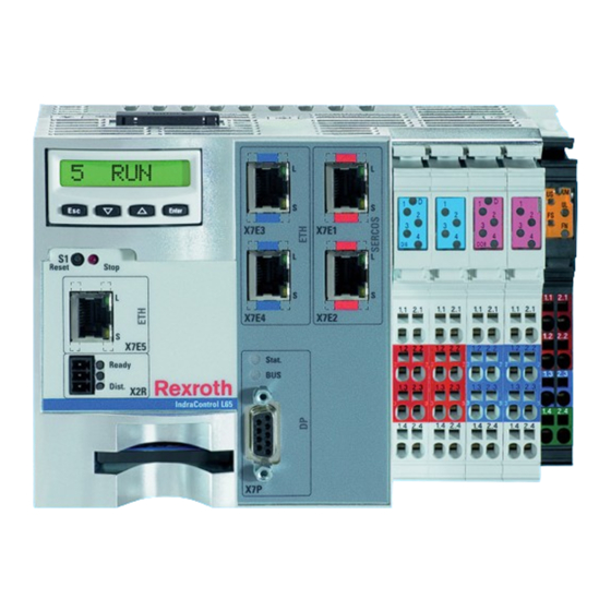
Interface view
Provides a visual overview of the control's interfaces.
Interfaces
Overview
Detailed table of all available interfaces and their specifications.
Mounting, demounting and electric installation
Installation notes
Provides essential notes for safe and effective installation.
Housing dimensions
Details the physical dimensions of different control models.
Mounting, demounting and electric installation
Housing dimensions L25
Specific housing dimensions for the L25 control model.
Mounting, demounting and electric installation
Housing dimensions of the fan
Details the physical dimensions of the fan.
Mounting, demounting and electric installation
Mounting the control
Guides the user through the process of mounting the control.
General information
Important safety notice regarding mounting under voltage.
Mounting, demounting and electric installation
Mounting the control on the top-hat rail
Step-by-step guide to mount the control onto a top-hat rail.
Mounting Rexroth Inline terminals (optional) in series
Instructions for mounting optional Inline terminals in series.
Mounting, demounting and electric installation
Mounting the shielding plate
Instructions for mounting the shielding plate for ESD protection.
Mounting function modules (optional)
Guidance on mounting optional function modules.
Mounting, demounting and electric installation
Mounting the fan (if necessary)
Instructions for mounting the fan if required for cooling.
Mounting, demounting and electric installation
Demounting the control
Procedures for safely removing the control.
Removing the first Rexroth Inline terminal (if Inline terminals were mounted)
Steps to remove the first Inline terminal.
Mounting, demounting and electric installation
Removing control from top-hat rail
Procedure to detach the control from the top-hat rail.
Mounting, demounting and electric installation
Demounting and changing the Inline terminals
Steps for removing and replacing Inline terminals.
Removing an Inline terminal
Detailed steps for removing an Inline terminal unit.
Mounting, demounting and electric installation
Electric installation
General information and warnings for electric installation.
General information
Crucial safety warnings for electrical installation.
Mounting, demounting and electric installation
Electric installation
Information on powering the control unit.
24 V voltage supply
Specifics about the 24V voltage supply setup.
Mounting, demounting and electric installation
Electric installation
Essential information for proper grounding of the system.
Mounting, demounting and electric installation
Electric installation
Explains the purpose of functional earth and grounding screw.
Mounting, demounting and electric installation
Electric installation
Importance and methods for proper shielding.
Connecting lines (for digital onboard inputs, outputs and voltage supply) to tension spring connection points
How to connect lines to tension spring terminals.
Mounting, demounting and electric installation
Electric installation
Guidelines for operating the control at high altitudes.
Mounting, demounting and electric installation
Electric installation
Details digital inputs on specific control models.
Mounting, demounting and electric installation
Electric installation
Details digital outputs on specific control models.
Mounting, demounting and electric installation
Electric installation
Refers to other manuals for additional interface descriptions.
Commissioning
Provides essential warnings before starting commissioning.
Commissioning steps
Outlines the step-by-step procedure for commissioning the control.
Device description
General information
Identifies and describes the various components of the control.
Error causes and troubleshooting
System is booting" and "No Compact Flash" displays
Explains specific system messages and their remedies.
Further operating and error displays and remedies - "Stop" LED
Details the meaning of the "Stop" LED and error handling.
Maintenance
General information
Specifies permitted maintenance tasks by the customer.
Regular maintenance tasks
Lists recommended regular maintenance activities.
Lithium battery
Explains the function and exchange of the lithium battery for SRAM.
Ordering information
Type code Lx5
Explains the type code structure for ordering controls.
Accessories and spare parts
Refers to chapter 5 for ordering accessories and spare parts.
Disposal
General information
Provides general guidelines for product disposal.
Return
Outlines the procedure and conditions for returning products.
Service and support
Service Germany
Provides contact details for service and support in Germany.
Service worldwide
Guides users on contacting local service offices worldwide.
Need help?
Do you have a question about the IndraControl L65 and is the answer not in the manual?
Questions and answers