Table of Contents
Advertisement
Advertisement
Chapters
Table of Contents

Related Manuals for REXROTH CS351


Summary of Contents for REXROTH CS351
- Page 1 CS351/ CC-CS351 3 609 929 B45 AC/06.2013 DE/EN RUN/STOP ERROR...
-
Page 2: Table Of Contents
3 609 929 B45/2013-06 | CS351/CC-CS351 Bosch Rexroth AG 55/108 Table of Contents About This Document ......................57 General safety instructions ....................58 Scope of delivery ........................62 Product description ........................63 Transport and storage ......................84 Assembly ............................85 Commissioning .......................... -
Page 3: B45/2013-06 | Cs351/Cc-Cs351 Bosch Rexroth Ag
56/108 Bosch Rexroth AG CS351/CC-CS351 | 3 609 929 B45/2013-06 © This document, as well as the data, speci- The data specified above only serves to de- scribe the product. No statements concern- fications, and other information set forth in it,... -
Page 4: About This Document
3 609 929 B45/2013-06 | CS351/CC-CS351 Bosch Rexroth AG 57/108 About This Document About This Document Scope of the documentation This documentation is applicable for the This manual contains important information CS351 and CC-CS351 Compact Systems. on the safe and appropriate assembly, trans-... -
Page 5: General Safety Instructions
2 “General safety instructions”. The Compact System has been manufac- Only use the Compact System CS351 in tured according to the accepted rules of cur- conjunction with a Rexroth ErgoSpin/CC-Er- rent technology. There is, however, still a dan-... - Page 6 3 609 929 B45/2013-06 | CS351/CC-CS351 Bosch Rexroth AG 59/108 General safety instructions Personnel qualification • Consequences: describes what occurs when the safety instructions are not ob- Assembly, commissioning and operation, dis- served assembly, service (including maintenance • Precautions: states how the hazard can...
- Page 7 60/108 Bosch Rexroth AG CS351/CC-CS351 | 3 609 929 B45/2013-06 General safety instructions During assembly NOTE Make sure the relevant system component is not under pressure or voltage before assem- NOTE indicates a situation which, if not bling the product or when connecting and avoided, could result in minor or moder- disconnecting plugs.
- Page 8 3 609 929 B45/2013-06 | CS351/CC-CS351 Bosch Rexroth AG 61/108 General safety instructions During cleaning DANGER Cover all openings with the appropriate pro- tective equipment in order to prevent deter- Insufficient emergency OFF equip- gents from penetrating the system. ment! Never use solvents or aggressive detergents.
-
Page 9: Scope Of Delivery
Dispose of the product in accordance with The delivery contents include: the currently applicable national regulations • 1 CS351 or CC-CS351 Compact System in your country. • 1 power supply connection cable (in acc. Batteries must not be disposed in the general... -
Page 10: Product Description
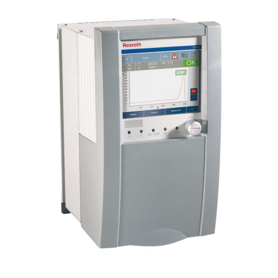
3 609 929 B45/2013-06 | CS351/CC-CS351 Bosch Rexroth AG 63/108 Product description Product description Performance description The Compact System combines a servo am- Compact System variants for tightening spin- plifier, power supply, display, controller, and dles include: slots for optional interface cards. - Page 11 64/108 Bosch Rexroth AG CS351/CC-CS351 | 3 609 929 B45/2013-06 Product description Device description Legend relating to Fig. 1: 1 Name plate 2 Front cover lock 3 Cable duct strip 4 Side cable ducts 5 Affixed pressure compensation membrane (do not remove)
-
Page 12: Inside The Front Cover
• Only in CS351E-D NK/ CS351S-D NK: – Interfaces for connection to the system Outside the front cover: bus 350 (XDAC1, XDAC2) • 1 USB device interface for CS351 control- ler (X3U3), The external interfaces of the integrated com- specification compatible with 2.0... - Page 13 66/108 Bosch Rexroth AG CS351/CC-CS351 | 3 609 929 B45/2013-06 Product description X3U3 XDAC1 XDAC2 XDS1 XDS2 Fig. 2: Available interfaces of the Compact System (interface components depending on CS variant) Reboot X6MSD2 X3U6 X3U7 X3U8 X7E4 X3C2 X7E5 XDVI2 Fig.
- Page 14 3 609 929 B45/2013-06 | CS351/CC-CS351 Bosch Rexroth AG 67/108 Product description Table 1: Interface combinations CS351S- CS351S- CS351S- CS351S- CS351S- CS351S- – D IL G IL D NK CS351E- CS351E- CS351E- CS351E- CS351E- CS351E- CS351E- Inter- D IL G IL...
- Page 15 68/108 Bosch Rexroth AG CS351/CC-CS351 | 3 609 929 B45/2013-06 Product description External interfaces Table 2: X1N pin assignment Description/ Voltage/ Signal function current X1N power supply connection interface L1 power supply 230 V /5 A, The compact system is delivered with an EU...
- Page 16 3 609 929 B45/2013-06 | CS351/CC-CS351 Bosch Rexroth AG 69/108 Product description XDS1 interface for hand-held nutrunner XDS2 interface for tightening spindle The ErgoSpin/CC-ErgoSpin hand-held nut- The tightening spindle is connected to the runner is connected to the Compact System...
-
Page 17: Xdn1
70/108 Bosch Rexroth AG CS351/CC-CS351 | 3 609 929 B45/2013-06 Product description Motor OFF interface XDN1 XDN1 CAUTION 1 2 3 4 Risk of damage to persons and property! The emergency OFF interface is no sub- Fig. 8: XDN1 stitute for an emergency stop facility. It... - Page 18 3 609 929 B45/2013-06 | CS351/CC-CS351 Bosch Rexroth AG 71/108 Product description The maximum torque at the CAUTION bolted connections of the termi- nals at XDN1 must not exceed Risk of damage to persons and prop- 0.3 Nm. erty! Dangerous shock currents due to insuffi-...
- Page 19 72/108 Bosch Rexroth AG CS351/CC-CS351 | 3 609 929 B45/2013-06 Product description Motor OFF protective circuit 1. Cut-out via the internal motor contactors After a cut-out via the motor contactor, the motor phases are electromechanically iso- lated from the power supply.
- Page 20 3 609 929 B45/2013-06 | CS351/CC-CS351 Bosch Rexroth AG 73/108 Product description 2. Cut-out via the end step In addition, the motor OFF can be switched via the end step or along with the cut-out via the motor contactors (double protection).
-
Page 21: X7E1
74/108 Bosch Rexroth AG CS351/CC-CS351 | 3 609 929 B45/2013-06 Product description Ethernet interface X7E1 The MAC address can be found on the name plate on the top of the Compact System. The interface has an 8-pin RJ45 socket (10/ 100 Base T) design. - Page 22 3 609 929 B45/2013-06 | CS351/CC-CS351 Bosch Rexroth AG 75/108 Product description A slot interface (A) B slot interfaces (B1, B2) This interface is intended for use of type A in- These interfaces are intended for use of type terface modules from Rexroth.
-
Page 23: X6C1
76/108 Bosch Rexroth AG CS351/CC-CS351 | 3 609 929 B45/2013-06 Product description Slot for the mass storage (X6C1) USB host interfaces (X3U1, X3U2) This interface is intended for the use of the These interfaces are designed as type A CF350 mass storage. -
Page 24: X3U4
3 609 929 B45/2013-06 | CS351/CC-CS351 Bosch Rexroth AG 77/108 Product description USB device interface (X3U3) This interface is intended for the connection of a PC for programming and parameteriza- tion. It is designed as a type B socket. It is compatible with USB 2.0 (maximum data rate... - Page 25 78/108 Bosch Rexroth AG CS351/CC-CS351 | 3 609 929 B45/2013-06 Product description Table 12: DVI interface (XDVI) assignment Signal Description/function Voltage/current TMDS data 2– Data 2– DVI differential TMDS data 2+ Data 2+ DVI differential TMDS data 2 shield Shield for data 2 PE potential n.c.
-
Page 26: Xdac1,
3 609 929 B45/2013-06 | CS351/CC-CS351 Bosch Rexroth AG 79/108 Product description Interfaces for connection to the system Table 13: Spacer bolts for network lines bus (XDAC1, XDAC2) Manu- Wrench The NK350 network coupler integrated in the fac- Thread Length Order no. - Page 27 80/108 Bosch Rexroth AG CS351/CC-CS351 | 3 609 929 B45/2013-06 Product description Interface XDAC1 (female) Interface XDAC2 (male) This interface is intended for connecting an This interface is intended for connecting an NKLx network cable in order to integrate fur- NKLx network cable in order to integrate fur- ther users.
- Page 28 3 609 929 B45/2013-06 | CS351/CC-CS351 Bosch Rexroth AG 81/108 Product description LED display XDAc1 The network status is indicated by the three LEDs on the front panel (see Fig. 21): • LED 1 describes the network status of the users connected to XDAC1, •...
- Page 29 82/108 Bosch Rexroth AG CS351/CC-CS351 | 3 609 929 B45/2013-06 Product description Further interfaces of the Hex coding switch On networked systems (sibracks, system variant with integrated boxes or compact systems), the valid ad- computer unit dress must be set on the hex coding switch before commissioning.
-
Page 30: X3C2
3 609 929 B45/2013-06 | CS351/CC-CS351 Bosch Rexroth AG 83/108 Product description Serial interface X3C2 USB interfaces X3U6, X3U7, X3U8 The interface is intended for connection of a These interfaces are designed as type A printer or scanner to the computer unit. The sockets. -
Page 31: Transport And Storage
84/108 Bosch Rexroth AG CS351/CC-CS351 | 3 609 929 B45/2013-06 Transport and storage Transport and storage LED indicators (St1, St2) LEDs St1 and St2 (see Fig. 25) show the op- For storing and transporting the product al- erating state of the computer unit. -
Page 32: Assembly
3 609 929 B45/2013-06 | CS351/CC-CS351 Bosch Rexroth AG 85/108 Assembly Assembly CAUTION Electrostatic discharge! Assembling the Compact System Damages to the compact system Comply with all the precautions for CAUTION ESD protection when handling com- ponents and modules! Avoid electro-... - Page 33 86/108 Bosch Rexroth AG CS351/CC-CS351 | 3 609 929 B45/2013-06 Assembly 252,5 Fig. 26: Wall bracket (dimensions in mm) 1 Wall bracket 2 Lift-out protection...
-
Page 34: Commissioning
3 609 929 B45/2013-06 | CS351/CC-CS351 Bosch Rexroth AG 87/108 Commissioning Commissioning The permissible installation position for the Compact System is vertical. During assembly, the Compact System CAUTION should have at least 10 mm space when lined up and at least 300 mm space above it. - Page 35 88/108 Bosch Rexroth AG CS351/CC-CS351 | 3 609 929 B45/2013-06 Commissioning Removing the front cover Assembly: You can remove the front cover to improve 1. Push the axle pins in and insert the front access to the interfaces. cover. 1. Release and open the front cover.
- Page 36 The integrated computer unit already has an Configuring the computer unit activated pre-installed Windows 7 operating system. After the CS351 Compact System has been CC variant: Setting the MCE factor switched on, the integrated computer unit is The nutrunner does not have to be adjusted...
- Page 37 90/108 Bosch Rexroth AG CS351/CC-CS351 | 3 609 929 B45/2013-06 Commissioning In the BS350 operating program: 1. Connect the BS350 operating program to the Compact System. 2. The BS350 displays an interface module IMpc 3608861118 for the computer unit in module slot B2.
- Page 38 3 609 929 B45/2013-06 | CS351/CC-CS351 Bosch Rexroth AG 91/108 Commissioning 4. "MEN Z87 Ethernet Adapter #2" must be Check whether the Compact System and the set under "Connect using:". computer unit are connected to each other. 5. Click "Internet Protocol Version 4 (TCP/ 1.
-
Page 39: Operation
92/108 Bosch Rexroth AG CS351/CC-CS351 | 3 609 929 B45/2013-06 Operation Operation NOTE CAUTION Important operation information Keep the air ways used for cooling Disconnecting plug connectors that the Compact System clear. are under voltage! The Compact System may only be op- Damages to the compact system erated in grounded networks. -
Page 40: Maintenance And Repair
3 609 929 B45/2013-06 | CS351/CC-CS351 Bosch Rexroth AG 93/108 Maintenance and repair Maintenance and repair Table 18: LED modes Color Diagnosis No power supply or low- DANGER voltage power supply avail- able Electrical voltages! Blue Power supply and low-volt-... - Page 41 94/108 Bosch Rexroth AG CS351/CC-CS351 | 3 609 929 B45/2013-06 Maintenance and repair Reboot function of the computer unit Exchanging fuses If you have to reset the operating system be- cause it is blocked by a running program or DANGER has crashed, push and hold the reboot button (see Fig.
- Page 42 3 609 929 B45/2013-06 | CS351/CC-CS351 Bosch Rexroth AG 95/108 Maintenance and repair Fig. 37: Fuses DANGER F1 Main circuit fuse Si 10 A, 250 V, Electrical voltages! 6.3x32 mm slow-blow, Manufacturer: ESKA/ENDRICH, order Electrocution number UL632.727 Make sure when assembling the front...
- Page 43 96/108 Bosch Rexroth AG CS351/CC-CS351 | 3 609 929 B45/2013-06 Maintenance and repair Changing the battery of the Compact System CAUTION When switched off, the installed battery has a service life of approximately four years from Risk of damage to persons and prop- the date of production.
- Page 44 3 609 929 B45/2013-06 | CS351/CC-CS351 Bosch Rexroth AG 97/108 Maintenance and repair • Remove the used-up battery. Under no cir- Variant with integrated computer unit: cumstances should conductive tools (e. g. Changing the battery of the computer tweezers) be used to remove batteries - unit short circuit danger.
- Page 45 98/108 Bosch Rexroth AG CS351/CC-CS351 | 3 609 929 B45/2013-06 Maintenance and repair Cleaning and care CAUTION Any dirt or liquids penetrating the device lead to malfunctions! Safe function of the Compact System is no longer ensured. Always provide for absolute clean- ness when working on the Compact System.
- Page 46 3 609 929 B45/2013-06 | CS351/CC-CS351 Bosch Rexroth AG 99/108 Maintenance and repair Maintenance Testing the residual-current-operated protective device The residual-current-operated protective device is only avail- able with the CS351E Compact System for ErgoSpin hand-held nutrunners. Check the function of the residual-current- operated protective device (RCD) by actuat- ing the test button.
-
Page 47: Decommissioning
100/108 Bosch Rexroth AG CS351/CC-CS351 | 3 609 929 B45/2013-06 Decommissioning Decommissioning Spare parts and accessories For the addresses of out national representa- The Compact System is a component that tions, please refer to www.boschrexroth.com does not require decommissioning. As a re-... -
Page 48: Disassembly And Replacement
3 609 929 B45/2013-06 | CS351/CC-CS351 Bosch Rexroth AG 101/108 Disassembly and replacement Disassembly and Proceed as follows to disassemble the Com- pact System: replacement The Compact System must be considered a 1. Switch off the power supply to the Com- unit. -
Page 49: Disposal
102/108 Bosch Rexroth AG CS351/CC-CS351 | 3 609 929 B45/2013-06 Disposal Disposal Extension and conversion Do not convert the Compact System. Environmental protection Careless disposal of the Compact System could lead to pollution of the environment. Troubleshooting Therefore, dispose of the device in accor-... -
Page 50: Technical Data
3 609 929 B45/2013-06 | CS351/CC-CS351 Bosch Rexroth AG 103/108 Technical data Technical data Table 21: General data Designation CS351E-D CS351E-G CS351S-D CS351S-G CS351E-D CS351S-D IL designation CS351E-D IL CS351E-G IL CS351S-D IL CS351S-G IL – – CC designation CC-CS351E- –... - Page 51 104/108 Bosch Rexroth AG CS351/CC-CS351 | 3 609 929 B45/2013-06 Technical data Table 21: (Fortsetzung) General data Designation CS351E-D CS351E-G CS351S-D CS351S-G CS351E-D CS351S-D IL designation CS351E-D IL CS351E-G IL CS351S-D IL CS351S-G IL – – CC designation CC-CS351E- –...
- Page 52 3 609 929 B45/2013-06 | CS351/CC-CS351 Bosch Rexroth AG 105/108 Technical data Table 21: (Fortsetzung) General data Designation CS351E-D CS351E-G CS351S-D CS351S-G CS351E-D CS351S-D IL designation CS351E-D IL CS351E-G IL CS351S-D IL CS351S-G IL – – CC designation CC-CS351E- –...
-
Page 53: Service And Sales
106/108 Bosch Rexroth AG CS351/CC-CS351 | 3 609 929 B45/2013-06 Service and sales Service and sales Service Sales We are always the right partner when it Bosch Rexroth AG comes to system know-how. Electric Drives and Controls Schraub- und Einpress-Systeme For any problem: Rexroth service Fornsbacher Str. - Page 54 3 609 929 B45/2013-06 | CS351/CC-CS351 Bosch Rexroth AG 107/108 Service and sales...
- Page 55 Bosch Rexroth AG Electric Drives and Controls Postfach 1161 D-71534 Murrhardt, Germany Fornsbacher Str. 92 D-71540 Murrhardt, Germany Tel.: +49 (0)71 92 22 208 Fax +49 (0)71 92 22 181 schraubtechnik@boschrexroth.de www.boschrexroth.com Ihr Ansprechpartner / Contact:...
Need help?
Do you have a question about the CS351 and is the answer not in the manual?
Questions and answers
型号Rexroth CS351S-D ,工作需要,需要力士乐拧紧枪的GSD文件,官网中没有找到