
Subscribe to Our Youtube Channel
Related Manuals for Branick 475


Summary of Contents for Branick 475
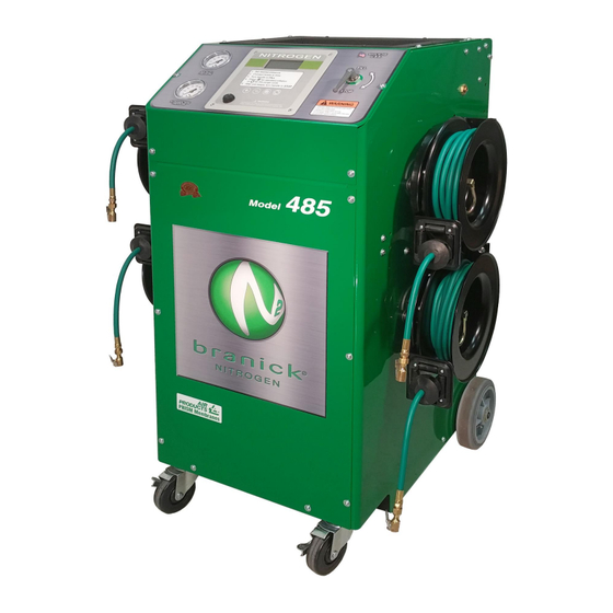
- Page 1 Installation, Operation MODEL 475/485/675/685 & Repair Parts NITROGEN INFLATION Information SYSTEMS Branick Industries, Inc. • 4245 Main Avenue • Fargo, North Dakota 58103 P/N: 81-0191E REV120413...
-
Page 2: Table Of Contents
TABLE OF CONTENTS _______________________________________________________ SAFETY INSTRUCTIONS DEFINITIONS SPECIFICATIONS INSTALLATION INSTRUCTIONS COMPONENT IDENTIFICATION PURGING THE SYSTEM PURITY ADJUSTMENT OPERATING INSTRUCTIONS TROUBLESHOOTING MAINTENANCE REPAIR PARTS REPAIR PARTS LIST WARRANTY SAFETY INSTRUCTIONS _____________________________________________________ ▪ NEVER allow unauthorized personnel to operate this product. ▪ NEVER use this product for anything other than its intended use. -
Page 3: Specifications
Display Increments 1 psi (0.1 bar) Dimensional data: Model 475 / 675 28.2 x 28.3 x 47.3 in (71.6 x 71.8 x 120.1 cm) Model 485 / 685 31.8 x 28.3 x 47.3 in (80.7 x 71.8 x 120.1 cm) -
Page 4: Installation Instructions
INTENDED USE _____________________________________________________________ The Nitrogen Inflation System is a pneumatic device designed to generate deoxygenated air for the purpose of inflating vehicle tires. INSTALLATION INSTRUCTIONS _______________________________________________ 1. Unpack and remove unit from shipping carton and pallet. 2. Inspect the unit for any visible damage. 3. -
Page 5: Component Identification
COMPONENT IDENTIFICATION ________________________________________________ ___________________________________________________________________________________________ Charge Indicator Auxiliary Nitrogen Port Optional Inflation Hose Port Nitrogen Sampling Port (1 each side) Air Inlet Pressure Gauge Auxiliary Valve Digital Inflator Purity Adjustment Dial Tire Fill Control Valve Oxygen Exhaust Vent Nitrogen Tank Pressure Gauge Air Inlet Valve (1/4 NPT) Power On/Off Button Particulate Filter... -
Page 6: Purging The System
PURGING THE SYSTEM (intial setup only) ______________________________________ Now you are ready to fill the internal 30 gallon tank with nitrogen. There may be “regular” air in the tank and this must be purged to obtain the proper nitrogen purity in the tank. On the particulate filter, rotate the Air Inlet Valve to the ON position (vertical). -
Page 7: Operating Instructions
OPERATING INSTRUCTIONS _________________________________________________ Power Requirements & Charging instructions ▪ The system is powered by an internal Sealed Lead Acid (SLA) 12 volt rechargeable battery. ▪ Charge system by plugging the electrical cord into the charger socket on the back of unit, and the other end into a 110/120 volt outlet. - Page 8 Example: To alter the number of purge cycles, follow these steps: 1. Turn on the power supply. 2. Display will show and check all LCD digits. 3. Display will show the current firmware version number, e.g., '.3.1.9'. 4. Display will show the program model variant, e.g., '349'. 5.
-
Page 9: Troubleshooting
6. When the alarm sounds the cycle is complete. 7. Turn the Fill Control valve handle to STOP and remove hoses from valve stems. To turn off the power to the inflator, flip the ON/OFF button to off. Emergency Stop To stop the inflation / deflation cycle, press any button on the front panel or turn the Fill Control valve handle from FILL to STOP. -
Page 10: Maintenance
MAINTENANCE _____________________________________________________________ NOTE: To avoid personal injury or damage to the Nitrogen Inflation System, permit only qualified personnel to perform maintenance. When cleaning or replacing filter elements and automatic float drains, disconnect airline from filters and turn Air Inlet valve to ON to allow air to drain from system. When Air Inlet Pressure Gauge reads zero psi, you can service the filters. -
Page 11: Repair Parts
REPAIR PARTS _____________________________________________________________ HOSE CONNECTING LEGEND EXAMPLE: A2 A = HOSE “A” 2 = FIGURE NUMBER Top Panel Detail FIGURE 1... - Page 12 HOSE CONNECTING LEGEND EXAMPLE: A2 A = HOSE “A” 2 = FIGURE NUMBER Tank & Membrane Detail FIGURE 2...
- Page 13 HOSE CONNECTING LEGEND EXAMPLE: A2 A = HOSE “A” 2 = FIGURE NUMBER Rear Panel Detail FIGURE 3...
- Page 14 HOSE CONNECTING LEGEND A = HOSE “A” EXAMPLE: A2 2 = FIGURE NUMBER Left Panel Detail FIGURE 4...
- Page 15 HOSE CONNECTING LEGEND EXAMPLE: A2 A = HOSE “A” 2 = FIGURE NUMBER Right Panel Detail FIGURE 5...
- Page 16 HOSE CONNECTING LEGEND EXAMPLE: A2 A = HOSE “A” 2 = FIGURE NUMBER Right Panel, Model 475/675 FIGURE 6...
-
Page 17: Repair Parts List
REPAIR PARTS LIST __________________________________________________ ITEM QTY. PART NO. DESCRIPTION 03-0617 BASE FRAME 03-0618 RIGHT SIDE PANEL 03-0619 LEFT SIDE PANEL 03-0620 HANDLE 06-0115 RIGHT HOSE REEL BRACKET 06-0116 LEFT HOSE REEL BRACKET 10-0029 MEMBRANE GROMMET 10-0031 ADHESIVE PAD 028-002 5/16-18 X 5/8 HHC SCREW 028-034 1/2-13 X 1-1/4 HHC SCREW 028-155... - Page 18 1/4 NPT M X 3/8 TUBE CONNECTOR 60-0192 1/4 NPT FEM BHD COUPLING 60-0193 1/4 NPT M X 3/8 TUBE ELBOW 60-0194 1/4 NPT M X 1/4 NPT FEM ELBOW (475/675) 60-0195 3/8 NPT MINI BALL VALVE 60-0196 1/4 SCHRADER BHD VALVE 60-0198...
- Page 19 1/2 OD (BLACK) TUBE D20-032 3/4 ID BRAIDED TUBE D20-038 1" CLEAR PVC TUBE D20-041 6 MM OD (RED) TUBE 03-0620 RIGHT SIDE PANEL (475/675) 03-0621 LEFT SIDE PANEL (475/675) 06-0047 HOSE BRACKET (475/675) 62-0020 25' HOSE ASS'Y (475/675) 64-0021...
-
Page 20: Warranty
Replacement is the exclusive remedy for defective product under this warranty. This warranty is expressly in lieu of all other warranties, including any implied warranty of merchantability or any implied warranty of fitness for a particular purpose of this product. Branick industries, inc. Shall not be liable for any consequential or incidental damages.
Need help?
Do you have a question about the 475 and is the answer not in the manual?
Questions and answers