Rockwell Automation Allen-Bradley Kinetix 5700 Series Installation Instructions Manual
Dc-bus power supply
Hide thumbs
Also See for Allen-Bradley Kinetix 5700 Series:
- User manual (456 pages) ,
- Selection manual (234 pages) ,
- Application technique (82 pages)
Table of Contents
Advertisement
Quick Links
Installation Instructions
Original Instructions
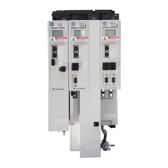
Kinetix 5700 DC-bus Power Supply
Catalog Numbers 2198-P031, 2198-P070, 2198-P141, 2198-P208
Topic
Summary of Changes
Topic
• Removed inch conversions from hole spacing dimensions to avoid errors due to rounding.
Page
1
2
2
2
3
4
5
8
11
12
14
14
Page
5
6
8
11
13
Advertisement
Table of Contents

Related Manuals for Rockwell Automation Allen-Bradley Kinetix 5700 Series


Summary of Contents for Rockwell Automation Allen-Bradley Kinetix 5700 Series
-
Page 1: Table Of Contents
Installation Instructions Original Instructions Kinetix 5700 DC-bus Power Supply Catalog Numbers 2198-P031, 2198-P070, 2198-P141, 2198-P208 Topic Page Summary of Changes About the DC-bus Power Supply Catalog Number Explanation Before You Begin Remove the Ground Screw in Select Power Configurations Install the DC-bus Power Supply Drill Hole Patterns Connector Data Wiring Requirements... -
Page 2: About The Dc-Bus Power Supply
• Wiring plug connector for shunt power (RC) connections installed on the drive • These installation instructions, publication 2198-IN009 Replacement connector sets are also available. See the Kinetix Servo Drives Specifications Technical Data, publication KNX-TD003, for more information. Rockwell Automation Publication 2198-IN009C-EN-P - March 2019... -
Page 3: Remove The Ground Screw In Select Power Configurations
ATTENTION: Risk of equipment damage exists. The drive-module ground configuration must be accurately determined. Leave the ground screw installed for grounded power configurations (default). Remove the screw for ungrounded, corner-grounded, and impedance-grounded power. Rockwell Automation Publication 2198-IN009C-EN-P - March 2019... -
Page 4: Install The Dc-Bus Power Supply
• Additional clearance left and right of the drive module is required when mounted adjacent to noise sensitive equipment or clean wire ways. • The recommended minimum cabinet depth is 300 mm (11.81 in.). Rockwell Automation Publication 2198-IN009C-EN-P - March 2019... -
Page 5: Drill Hole Patterns
• Mount the DC-bus power supply anywhere within the cluster, whatever makes the best use of panel space. If multiple 2198-P208 power supplies are mounted within the same cluster, mount them adjacent to each other anywhere within the cluster. Rockwell Automation Publication 2198-IN009C-EN-P - March 2019... -
Page 6: Added 2198-Dcbuscond-Rp312 Dc-Bus Conditioner Module To Diagram
Lower Mounting Hole Applies to 2198-P141 and 2198-P208 Power Supplies 2198-S086-ERSx and 2198-S130-ERSx Inverters, and 2198-D057-ERSx Inverters 420 mm Lower Mounting Hole Applies to only 2198-S160-ERSx Single-axis Inverters 465 mm Lower Mounting Hole Rockwell Automation Publication 2198-IN009C-EN-P - March 2019... - Page 7 DC-bus Power Supply is Shown DC-bus Power Supply Cat. No. mm (in.) mm (in.) mm (in.) mm (in.) 2198-P031 55 (2.17) 300 (11.8) 358 (14.1) 2198-P070 252 (9.9) 2198-P141 85 (3.35) 375 (14.8) 433 (17.0) 2198-P208 Rockwell Automation Publication 2198-IN009C-EN-P - March 2019...
-
Page 8: Connector Data
Link speed status indicators 24V control input power (CP) connector Zero-stack mounting tab/cutout Link/Activity status indicators AC Input power (IPD) connector Module status indicator Contactor enable (CED) connector Cooling fan Network status indicator Ground terminal Rockwell Automation Publication 2198-IN009C-EN-P - March 2019... - Page 9 DC-bus power supply. In addition, the AC three-phase contactor control string must be wired in series with the contactor-enable relay at the contactor enable (CED) connector. Refer to the Kinetix 5700 Servo Drives User Manual, publication 2198-UM002, for wiring examples. Rockwell Automation Publication 2198-IN009C-EN-P - March 2019...
- Page 10 + TX Transmit port (-) data terminal - TX Standard RJ45 Receive port (+) data terminal + RX – – – – Receive port (-) data terminal - RX – – – – Rockwell Automation Publication 2198-IN009C-EN-P - March 2019...
-
Page 11: Wiring Requirements
• Use motor power connectors only for connection purposes. Do not use them to turn the unit on and off. • Ground shielded power cables to prevent potentially high voltages on the shield. Rockwell Automation Publication 2198-IN009C-EN-P - March 2019... -
Page 12: Circuit Breaker/Fuse Specifications
The Kinetix 5700 power supplies use internal solid-state motor short-circuit protection and, when protected by suitable branch circuit protection, are rated for use on a circuit that can deliver up to 200,000 A (fuses) and 65,000 A (circuit breakers). Rockwell Automation Publication 2198-IN009C-EN-P - March 2019... -
Page 13: Updated The Ul/Csa And Iec Circuit Protection Specifications
Kinetix 5700 DC-bus Power Supply Rockwell Automation Publication 2198-IN009C-EN-P - March 2019... -
Page 14: Specifications
Provides declarations of conformity, certificates, and other Product Certifications website, rok.auto/certifications certification details. Industrial Automation Wiring and Grounding Guidelines, Provides general guidelines for installing a Rockwell publication 1770-4.1 Automation industrial system. You can view or download publications at http://www.rockwellautomation.com/global/literature-library/overview.page. Rockwell Automation Publication 2198-IN009C-EN-P - March 2019... - Page 15 Kinetix 5700 DC-bus Power Supply Notes: Rockwell Automation Publication 2198-IN009C-EN-P - March 2019...
- Page 16 Rockwell Automation maintains current product environmental information on its website at http://www.rockwellautomation.com/rockwellautomation/about-us/sustainability-ethics/product-environmental-compliance.page. Allen-Bradley, CompactLogix, ControlLogix, Kinetix, Rockwell Software, and Rockwell Automation are trademarks of Rockwell Automation, Inc. Trademarks not belonging to Rockwell Automation are property of their respective companies. Rockwell Otomasyon Ticaret A.Ş., Kar Plaza İş Merkezi E Blok Kat:6 34752 İçerenköy, İstanbul, Tel: +90 (216) 5698400...
Need help?
Do you have a question about the Allen-Bradley Kinetix 5700 Series and is the answer not in the manual?
Questions and answers