Advertisement
Quick Links
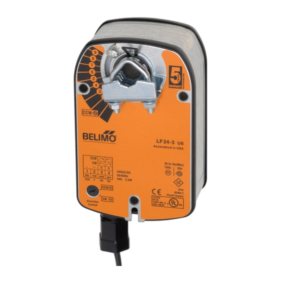
LF24-3 (-S) US
On-off, Spring Return Fail-Safe, Reversible, Floating Point, 24V
LISTED
U L
94D5
TEMP. IND &
.
REG. EQUIP
Technical Data
LF24-3 (-S) US
Power supply
24 VAC ± 20% 50/60 Hz
24 VDC ± 10%
Power consumption
running: 2.5 W;
Transformer sizing
5 VA (class 2 power source)
Electrical connection
LF24-3 US
LF24-3-S US 3 ft, 18 GA appliance
Overload protection
electronic throughout 0 to 95° rotation
1000 Ω (0.6w) control inputs
Input impedance
Angle of rotation
max. 95°, adjust. with mechanical stop
Torque
35 in-lb [4 Nm]
Direction of rotation
spring: reversible with cw/ccw mounting
motor: reversible with built-in switch
Position indication
visual indicator, 0° to 95° (0° is
spring return position)
Auxiliary switch
1 x SPDT 3A (0.5A) @ 250 VAC, UL listed
(LF24-3-S
)
adjustable 0° to 95° (double insulated)
US
Running time
motor: 150 sec constant,
spring: < 25 sec
Humidity
5 to 95% RH non-condensing
Ambient temperature
-22°F to +122°F [-30°C to +50°C]
Storage temperature
-40°F to +176°F [-40°C to +80°C]
Housing
NEMA type 2 /IP54
Housing material
zinc coated metal
Agency listings
UL 873 listed; CSA C22.2 No. 24
certified, CE
Noise level
max:
Servicing
maintenance free
Quality standard
ISO 9001
Weight
LF24-3
LF24-3-S 3.6 lbs (1.45 kg)
70
holding: 1 W
3 ft, plenum rated cable
cables (2)
1/2" conduit connector
independent of load
@-4°F to +122°F [-20°C to +50°C]
< 60 sec
@-22°F [-30°C]
running < 30 db (A)
spring return 62 dB (A)
3.1 lbs (1.40 kg)
Torque min. 35 in-lb, for control of air dampers
Application
For modulation or on-off control of dampers in HVAC systems.
Actuator sizing should be done in accordance with the damper
manufacturer's specifications.
The actuator is mounted directly to a damper shaft from 3/8"
up to 1/2" in diameter by means of its universal clamp, 1/2"
shaft centered at delivery. For shafts up to 3/4" use K6-1
accessory. A crank arm and several mounting brackets are
available for applications where the actuator cannot be direct
coupled to the damper shaft.
Control is floating point from a triac or relay, or on-off from an
auxiliary contact from a fan motor contactor, controller, or
manual switch.
Operation
The LF series actuators provide true spring return operation for
reliable fail-safe application and positive close-off on air tight
dampers. The spring return system provides consistent torque
to the damper with, and without, power applied to the actuator.
The LF series provides 95° of rotation and is provided with a
graduated position indicator showing 0 to 95°.
The LF24-3 (-S) US uses a brushless DC motor which is con-
trolled by an Application Specific Integrated Circuit (ASIC) and a
microprocessor. The microprocessor provides the intelligence to
the ASIC to provide a constant rotation rate. The ASIC monitors
and controls the brushless DC motor's rotation and provides a
digital rotation sensing function to prevent damage to the actua-
tor in a stall condition. The actuator may be stalled anywhere in
its normal rotation without the need of mechanical end switches.
Power consumption is reduced in holding mode.
The LF24-3-S US version is provided with 1 built-in auxiliary
switch. This SPDT switch is provided for safety interfacing or
signaling, for example, for fan start-up. The switching function
is adjustable between 0° and 95°. The auxiliary switch in the
LF24-3-S US is double insulated so an electrical ground is not
necessary.
Dimensions
[All numbers in brackets are in millimeters.]
Standard:
3/8" to 1/2"
3/8" to 7/16"
3.86"
Optional
[98]
1/2" to 3/4"
1.93"
w/K6-1
[49]
accessory
7.67" [195]
6.10" [155]
0.98"
[25]
0.39" [10]
0.256" [6.5]
3.15" [80]
0.79"
[20]
0.5"
[12.7]
3.66" [93]
0.71" [18]
4.92" [125]
0.74" [18.7]
3.23" [82]
2.24"
[57]
0.25" [6.3]
®
Advertisement

Related Manuals for Belimo LF24-3 US


Summary of Contents for Belimo LF24-3 US
- Page 1 0 to 95°. Transformer sizing 5 VA (class 2 power source) Electrical connection LF24-3 US 3 ft, plenum rated cable The LF24-3 (-S) US uses a brushless DC motor which is con- LF24-3-S US 3 ft, 18 GA appliance...
- Page 2 Note: When using LF24-3 (-S) US actuators, only use tured by Belimo. accessories listed on this page. 24 VAC Transformer For Actuator Wiring Information and Diagrams, Line Please See Belimo Wiring Guide (pg 349). Volts WARNING Live Electrical Components! Common During installation, testing,...
-
Page 3: Installation Instructions
Preliminary steps 1. Rotate the damper to its failsafe position. If the shaft rotates 1. Belimo actuators should be mounted indoors in dry, rela- counterclockwise, mount the “CCW” side of the actuator out. If it tively clean environment free from corrosive fumes. If the rotates clockwise, mount the actuator with the “CW”... - Page 4 Installation Instructions ® Mechanical Operation The actuator is mounted directly to a damper shaft up to 1/2” in diameter by means of its universal clamp, or up to a 3/4” shaft with the optional K6-1 clamp. A crank arm and several mounting brackets are available for applications where the actuator cannot be direct coupled to the damper shaft.
- Page 5 For power failures over 25 seconds, The LF24, modulating actuators (LF24-SR US, LF24-3 US, the actuator will be at it fail-safe position and will go through LF24-MFT US) are protected against overload by digital tech- the start up initialization again.
- Page 6 Installation Instructions ® Quick-Mount Visual Instructions for Mechanical Installation Mechanical Angle of Rotation Limiting The LF actuators are provided with an adjustable stop to limit Using the universal clamp: the rotation of the actuator. This function works in conjunction 1. Loosen the end stop fastening screw using a #2 Phillips with the universal clamp or the optional position indicator.
- Page 7 Installation Instructions ® Auxiliary Switches The …-S model actuators are equipped with an adjustable auxiliary switch used to indicate damper position or to inter- face additional controls or equipment. Switching positions can be set over the full 0 to 95° rotation simply by setting a switch on the actuator.
- Page 8 Multiple actuators positioned by the same control signal may Brushless DC Motor Operation be powered from multiple transformers provided the following Belimo's brushless DC motor spins by reversing the poles of rules are followed: stationary electromagnets housed inside rotating permanent 1.
-
Page 9: Startup And Checkout
• If multiple transformers are used with one control signal, make sure all No. 1 wires are tied together and tied to control signal negative (-). • Controllers and actuators must have separate 24 VAC/VDC power sources. Note 2 If failure occurs within 5 years from original installation date, notify Belimo and give details of the application.
Need help?
Do you have a question about the LF24-3 US and is the answer not in the manual?
Questions and answers