
Related Manuals for Belimo LF-2 Series


Summary of Contents for Belimo LF-2 Series
- Page 1 Actuators for heating, ventilation, air conditioning LF-2 Product Information Damper actuators with spring return...
- Page 2 0.8 m 1.5 m 3.6 m 0.8 m For more information, please contact your Belimo Representative or order any brochures you need by fax. Fax to: BELIMO (address overleaf) Please send us product brochures on the following damper actuators: LM...
-
Page 3: Table Of Contents
Spring return actuator, modulating LF24-SR Control/monitoring functions LF24-SR Mechanical accessories Note Mounting accessories LF... Using BELIMO damper actuators The actuators listed in this catalogue are intend- General mounting accessories ed for the operation of air dampers in HVAC systems. Mounting instructions... -
Page 4: Lf24
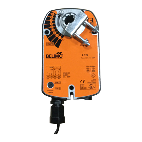
LF24, LF24-S Spring return actuators 4 Nm Dampers up to approx. 0.8 m Open/Close actuator (AC/DC 24 V) Control by single-pole contact Application For the operation of air dampers that perform safety functions (e.g. frost and smoke protection, hygiene, etc.). Mode of operation The LF... -
Page 5: Lf230
LF230, LF230-S Spring return actuators 4 Nm Dampers up to approx. 0.8 m Open/Close actuator (AC 230 V) Control by single-pole contact Application For the operation of air dampers that perform safety functions (e.g. frost and smoke protection, hygiene, etc.). Mode of operation The LF... -
Page 6: Adjusting The Auxiliary Switch
Adjusting the auxiliary switch LF24-S, LF230-S Mounting side R Starting point: Actuator in safe position Procedure – Turn the knob of the auxiliary switch un- til the tip of the arrow is pointing to the required switching position (see left). Example: Switching point setting = .4 corresponds to 40% angle of rotation. - Page 7 LF24-3 Spring return actuator 4 Nm Dampers up to approx. 0.8 m Modulating actuator (AC/DC 24 V) 3-point control Application For the operation of air dampers that perform safety functions (e.g. frost and smoke protection, hygiene, etc.). Mode of operation The LF24-3 is controlled by a 3-point sig- nal.
-
Page 8: Examples Of Control Modes Lf24-3
Examples of control modes LF24-3 Open/Close mode with single-wire control AC 24 V Connect via safety Mounting side isolating transformer DC 24 V Reversing switch (Y 2 ) Parallel connection of several LF24-3 actuators is possible. Power consumption must be observed. 3-point control by switch Connect via safety AC 24 V... -
Page 9: Lf24-Sr
LF24-SR Spring return actuator 4 Nm Dampers up to approx. 0.8 m Modulating actuator (AC/DC 24 V) Control DC 0...10 V and position feedback DC 2...10 V Application For the operation of air dampers that perform safety functions (e.g. frost and smoke protection, hygiene, etc.). - Page 10 Control and monitoring functions LF24-SR Remote control 0...100% Minimum position AC 24 V Connect via safety Connect via safety AC 24 V isolating transformer isolating transformer SGA24, SGF24 SGA24, SGF24 SGE24 SGE24 Y [ V ] Positioner Positioner 10 V Y DC 0...10 V (from controller) min.
-
Page 11: Mounting Accessories Lf
Mounting accessories LF... K6-1 K6-1 Spindle clamp Suitable for damper spindles 16...20 mm diameter. 16...20 The spindle clamp is secured to the ac- tuator by means of a circlip. KH-LF (Application example see page 14) KH-LF Crank arm with slot width 8.2 mm Suitable for damper spindles 8...16 mm diameter. -
Page 12: General Mounting Accessories
General mounting accessories Universal crank arm Zinc-plated steel; suitable for damper spindles Ø 10...18 mm or 10...14 mm, slot width 8.2 mm. Ball joint Zinc-plated steel; suitable for use with KH8 universal crank arms and round steel rod Ø 8 mm. KG10 KG10 Ball joint... -
Page 13: Direct Mounting
Instructions for direct mounting 8...16 8...16 ZDB-LF ZDB-LF . 1 0 0 . 1 0 0 3 7 . . 3 7 . . ZDB-LF... - Page 14 Instructions for mounting with linkage (ZG-LF… kit) Flat mounting (fig. 1) Kit specification ZG-LF1 ➀ 1 mounting bracket LF ➂ 1 crank arm ⁄ ” ➃ 1 circlip LF ➄ 2 ball joints KG8 3 screws M6 x 67 3 nuts M6 3 self-tapping screws 4.2 x 13 ➅...
- Page 15 Mounting instruction for tight-sealing dampers Installation steps as example 1. Move damper blades to the fail-safe position (a) and determine the orienta- tion of the universal clamp. 2. Engage the actuator on the shaft as close as possible to the determined ori- entation.
Need help?
Do you have a question about the LF-2 Series and is the answer not in the manual?
Questions and answers