Table of Contents
Advertisement
Quick Links
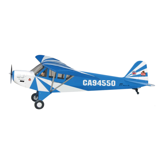
1/3 CLIPPED WING CUB
1/3 CLIPPED WING CUB
Requires: 80 cc gasoline engine,
Wing Span
Wing Area
Flying Weight
Fuselage Length
Warning! This model is not a toy.
It is designed for maximum performance. Please seek advice if one is not familiar with this kind
of engine powered precision model. Operating this model without prior preparation may cause
injuries. Remember, safety is the most important thing. Always keep this instruction manual at
hand for quick reference.
THE WORLD MODELS
MANUFACTURING CO., LTD.
FACTORY PRE-FABRICATED
ALMOST-READY-TO-FLY (ARF) SERIES
MADE IN CHINA
www.theworldmodels.com
4-channel radio w/ 6 servos.
Specifications
* Specifications are subject to change without notice. *
120 in / 3050 mm
2402 sq in / 155 sq dm
27.5 lbs / 12500 g
91.5 in / 2330 mm
INSTRUCTION MANUAL
Advertisement
Table of Contents

Related Manuals for The World Models Manufacturing A186C


Summary of Contents for The World Models Manufacturing A186C
- Page 1 INSTRUCTION MANUAL 1/3 CLIPPED WING CUB 1/3 CLIPPED WING CUB Requires: 80 cc gasoline engine, 4-channel radio w/ 6 servos. Specifications Wing Span 120 in / 3050 mm Wing Area 2402 sq in / 155 sq dm Flying Weight 27.5 lbs / 12500 g Fuselage Length 91.5 in / 2330 mm * Specifications are subject to change without notice.
-
Page 2: Before You Begin
1/3 CLIPPED WING CUB 1/3 CLIPPED WING CUB INDEX BEFORE YOU BEGIN PARTS LIST ASSEMBLY P.3-P.12 SAFETY PRECAUTIONS P.12 BEFORE YOU BEGIN Read through the manual before you begin, so you will have an overall idea of what to do. Check all parts. - Page 3 Parts List 1. MAIN WING -- 1 pair SWIVEL CLEVIS HORN FAIRING PL4610010 -- 2 sets HEAVY DUTY HORN BRACKET PL4112400 -- 2 sets 2. HEAVY DUTY CLEVIS P14112200 -- 4 sets HEAVY DUTY SERVO HORN PL412033 -- 2 sets SCREW PM4x60mm -- 2 pcs HEAVY DUTY CLEVIS PL4112200 -- 4 sets M4 NYLON INSERT LOCK NUT -- 2 pcs...
-
Page 4: Aileron Servo
Main Wing Aileron Servo Lead Pre-glued Bottom View Aileron servo PM 2 x 12 mm PL4120300 PM4x60mm Screw M4 NYLON INSERT LOCK NUT M2 Nut Heavy Duty Horn Bracket M4 Nylon Insert Lock Nut M2 Nut Heavy Duty Clevis PM2x8mm Pushrod Ø2.3x123mm PM4 x 60mm... -
Page 5: Wing Struts
Wing Struts 280mm Main Wing Strut 260mm PM4x20MM PM4x20mm Screw 174mm 184mm d4xD12mm Washer Washer d4xD9mm 373mm 331mm 3.5mm d4xD9mm Washer PM4 x 20mm M4 NYLON INSERT LOCK NUT M4 NYLON INSERT LOCK NUT Washer d4xD12mm Bottom View Stabilizer & Elevator Temporary install the main wing, adjust (Stabilizer) leveling of the stabilizer to make it as... -
Page 6: Tail Landing Gear
Tail Landing Gear PA 3.5x16mm Screw PA3.5 x16mm PWA 2 . 5x12mm Screw Spring PWA2.5 x 12mm M3x3mm Set Screw 2.5mm COPPER PLATE 1.5mm 1.5x10x60mm Bottom View Main Landing Gear PM4x30mm Screw PM4x30mm d4xD9mm PA 3x14mm Screw Washer 1.5mm ALU.PLATE PA 4x25mm Screw 3x15x77mm PA4x25mm... - Page 7 Engine M6x30 SOCKET HEAD SCREW d6xD15mm Washer 7.2mm M6 Blind Nut SOCKET HEAD SCREW M6 Blind Nut M6x30 mm washer d6xD15mm Cowling First insert the grommet to the cowling then apply screw. PWA3x12mm Screw d2.5x8.5mm Silicon Grommet d2.5xD8.5mm silicon Grommet COMPLETED 1.5mm PWA3x12mm...
-
Page 8: Elevator Pushrod
Fuel Tank Install Wood 12x12x197mm (For fixing fuel tank) Fuel Tank Bottom View Fuel Tank 1500cc COMPLETED Elevator Pushrod PM4x35mm Screw M4 NYLON INSERT LOCK NUT M4 Nylon Insert Heavy Duty Horn Bracket Lock Nut M2 Nut Heavy Duty Clevis PM2x8mm PM4x35mm PA1.7x8mm... - Page 9 Flying Wire Copper Tube 3mm Set Screw d3.6mm Collar Press down the center 1/3 portion PM 3x18mm Screw M3 NYLON INSERT LOCK NUT d5xD6.4x10mm M3x3mm Set SCREW Windows Window A Window B COMPLETED COMPLETED Securely glue the windows to the fuselage. Servo Set LINKAGE CONNECTOR 3 X 3mm Set Screw...
-
Page 10: Radio Equipment
Radio Equipment lnstall and arrange the servo as shown in the diagram. Sponge Battery Receiver Throttle Pushrod Plastic tube D1.2x480mm Throttle Servo d2xD3x300mm Bottom View Pilot PWA 2x12mm Screw PWA 2x12mm Screw PC101110A Wind Shield PWA2.3x12mm Screw PWA2.3x12mm d1.5x6.5mm Silicon Grommet M2 NYLON INSERT LOCK NUT 5xD6 silicon Grommet... - Page 11 Main Wing Step 1. Insert the aluminum wing tube with the pre-drilled hole end into the right wing. Align the lines marked at the wing root and wing tube and apply the PM3x30mm machine screw through the pre-drilled hole on top of the wing. ( please confirm the alignment of the hole by putting a 2.5mm diameter rod through the pre-drilled wing hole before applying the screw ) PM3x30mm Screw The hole on the wing tube is pre-threaded, do not over tighten the PM3mm screw, the set up...
- Page 12 Wing Struts PM4X16mm Screw Washer d4x D12mm Washer d4xD12mm PM4x16mm M4 NYLON INSERT LOCK NUT M4 NYLON INSERT LOCK NUT Wing Setting Adjust the wing and fuselage configuration as shown in the diagrams. A = A ' B = B ' C = C ' P.11...
-
Page 13: Control Throws
Control Throws Adjust the control throws as shown in the diagram. These throws are good for general flying. You can adjust according Rudder to your personal preference. 65mm 65mm Elevator 50mm 50mm Aileron 40mm 40mm The ideal C.G. position is 150mm(5.9in)behind the leading edge measured at where the wing meets the fuselage. - Page 14 LINKAGE CONNECTOR HW7111030 & HW7111060 Drill 2mm hole at servo horn. Insert linkage connector into servo horn. Make sure shoulder of screw is cleared from servo horn. Add washer to reduce play if necessary. Shoulder Tighten up the round nut against the shoulder.
- Page 15 Usage of the transparent 3D template ge e e o o o o o f f f t nt nt t 3 3 3 3 3 3 D D This transparent 3D template is s t t emplate mplate mpla mpla mpla a te...
- Page 16 http://www.theworldmodels.com A186C0701...
Need help?
Do you have a question about the A186C and is the answer not in the manual?
Questions and answers